Yamaha RX-V663 Black: Customizing this unit (MANUAL SETUP)
Customizing this unit (MANUAL SETUP): Yamaha RX-V663 Black

CUSTOMIZING THIS UNIT (MANUAL SETUP)
Customizing this unit (MANUAL SETUP)
You can use the following parameters in “SET MENU” to adjust a variety of system settings and customize the way this
unit operates. Change the initial settings (indicated in bold under each parameter) to reflect the needs of your listening
environment.
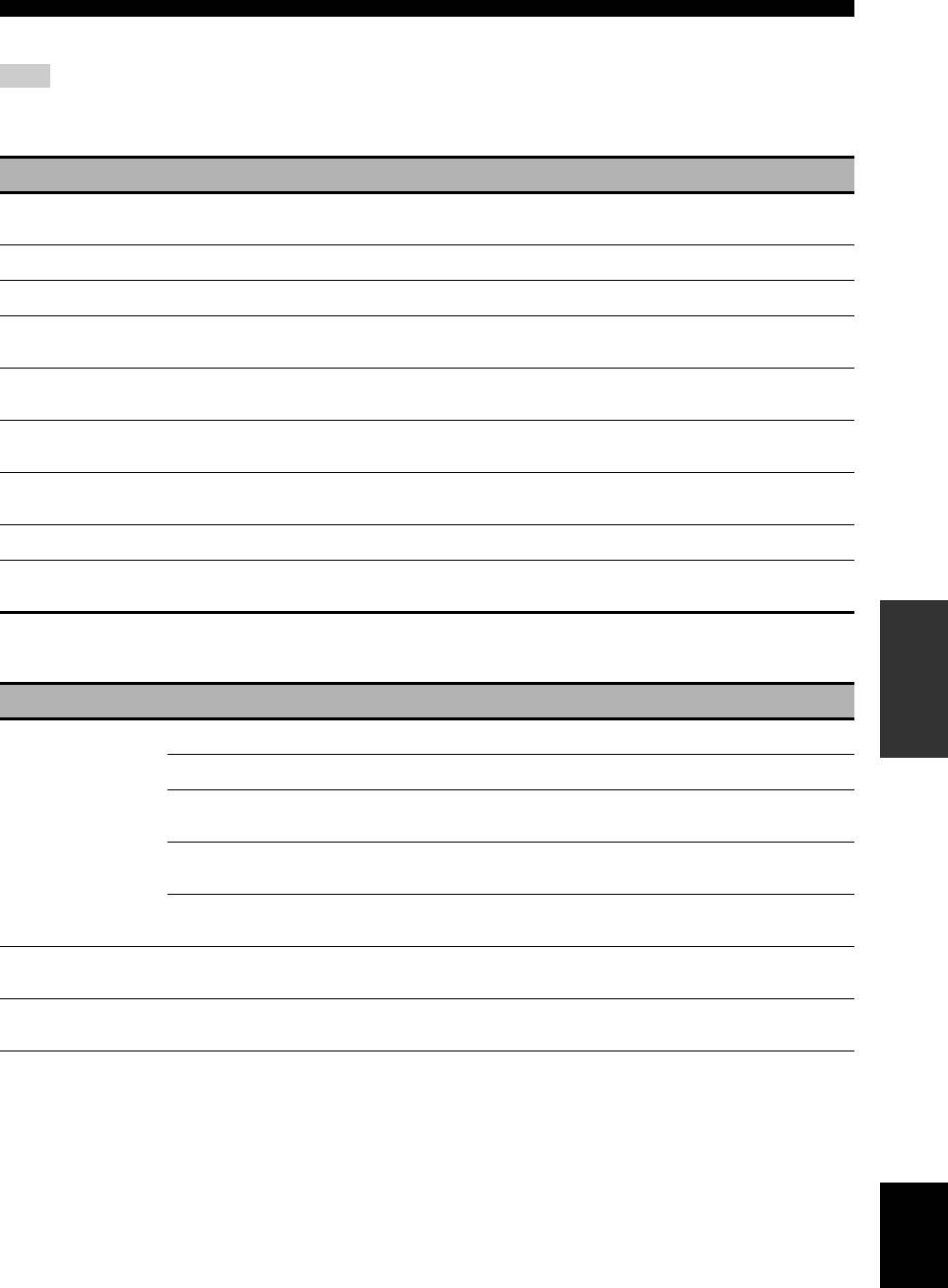
■ Auto setup AUTO SETUP
Use this feature to automatically adjust speaker and system parameters (see page 32).
■ Manual setup MANUAL SETUP
Use this feature to manually adjust speaker and system parameters.
Basic menu 1 BASIC MENU
Menu Parameter Functions Page
A)SPEAKER SET
EXTRA SP ASSIGN
Selects the function of the speakers connected to the EXTRA SP
76
speaker terminal.
LFE/BASS OUT
Selects the speakers that output the LFE (low-frequency effect) and the
76
low-frequency signals.
FRONT SP
Selects the size of the front speakers. 77
CENTER SP
Selects the size of the center speaker. 77
SUR. L/R SP
Selects the size and number of the surround speakers. 77
SUR.B L/R SP
Selects the size and number of the surround back speakers. 77
OPERATION
ADVANCED
CROSS OVER
Selects the crossover frequency of all the speakers set to “SML” (or
78
“SMALL”) in “SPEAKER SET” (see page 77).
SUBWOOFER PHASE
Switches the phase of your subwoofer if bass sounds are lacking or
78
unclear.
B)SP LEVEL
FR.L/FR.R/CNTR/
Adjust the balance the speaker levels between the front left or
78
SUR.L/SUR.R/
surround left speakers and each speaker selected in “SPEAKER SET”
SBL/SBR/SWFR/
(see page 76).
PR.L/PR.R
C)SP DISTANCE
UNIT
Selects the unit to adjust the speaker distance. 79
FRONT L/FRONT R/
Adjust the distance of each speaker and the delay applied to the
79
CENTER/SUR. L/
respective channel.
SUR. R/SBL/SBR/
SWFR/PRNS L/
PRNS R
D)TEST TONE
— Turns the test tone output on or off for the “SPEAKER SET”, “SP
79
LEVEL”, and “SP DISTANCE” settings.
English
71 En

Customizing this unit (MANUAL SETUP)
Volume menu 2 VOLUME MENU
Parameter Functions Page
ADAPTIVE DRC
Selects whether this unit automatically adjusts the dynamic range in conjunction with the
80
volume level or not.
ADAPTIVE DSP LEVEL
Selects whether this unit adjusts the DSP effect level automatically in conjunction with the
80
volume level or not.
MUTE TYPE
Adjusts how much the mute function reduces the output volume (see page 45). 80
MAX VOL.
Sets the maximum volume level of the main zone. 80
INIT. VOL.
Sets the volume level of the main zone when the power of this unit is turned on. 80
Sound menu 3 SOUND MENU
Menu Parameter Functions Page
A)EQUALIZER
EQ TYPE SELECT
Selects the type of equalizer. 81
GEQ
Adjusts the tonal quality of the speakers when you set “EQ TYPE
81
SELECT” to “GEQ”.
TEST
Selects whether this unit outputs the test tone while making
81
adjustments of “GEQ” or not.
B)LFE LEVEL
SPEAKER
Adjusts the speaker LFE level. 82
HEADPHONE
Adjusts the headphone LFE level. 82
C)DYNAMIC
SPEAKER
Adjusts the amount of the dynamic range compression of the speakers. 82
RANGE
HEADPHONE
Adjusts the amount of the dynamic range compression of the
82
headphones.
D)LIPSYNC
HDMI AUTO
Selects whether this unit activates the automatic audio and video
83
synchronization function (automatic lip sync) or not.
AUTO
Makes fine adjustments of the audio delay when the automatic audio
83
and video synchronization function is active.
MANUAL
Adjustment the audio delay manually when the connected video
83
monitor is not compatible with the automatic audio and video
synchronization function or “HDMI AUTO” is set to “OFF”.
E)EXTD SUR.
— Use this feature to enjoy 6.1/7.1-channel playback for multi-channel
83
sources using the Dolby Pro Logic IIx, Dolby Digital EX, or DTS-ES
decoders by using the connected surround back speakers.
72 En
Customizing this unit (MANUAL SETUP)
Input menu 4 INPUT MENU
Note
Some parameters described below may not be available for all input sources and some parameters are only available for specific input
sources.
Parameter Functions Page
I/O ASSIGNMENT
Assigns the input/output jacks according to the component to be used if the initial settings of
84
this unit do not correspond to your needs.
INPUT RENAME
Changes the name of the input source that appears in the OSD and in the front panel display. 85
VOL. TRIM
Adjusts the level of the signal input at each jack. 85
DECODER MODE
Switches the decoder activation mode. You can designate the reassigned digital input jacks for
85
DTS signals.
STANDBY CHARGE
Selects whether this unit charges the battery of the stationed iPod or not when this unit is in the
85
standby mode (see page 29).
START PAIRING
Pair the connected Yamaha Bluetooth adapter (such as YBA-10, sold separately) with a
86
Bluetooth component (see page 62).
BGV
Selects the video source played back in the background of the sources input at the MULTI CH
86
INPUT jacks.
INPUT CH
Selects the number of channels input from an external decoder. 86
FRONT
Selects the analog jacks at which the front channel signals from an external decoder are input
86
when you set “INPUT CH” to “8CH”.
OPERATION
ADVANCED
Option menu 5 OPTION MENU
Menu Parameter Functions Page
A)DISPLAY SET
DIMMER
Adjusts the brightness of the front panel display. 87
OSD SHIFT
Adjusts the vertical position of the OSD. 87
OSD-SOURCE
Sets the amount of time to display the iPod menu in the video monitor
87
after you perform a certain operation.
OSD-AMP
Sets the amount of time to display the status information screen after
87
you perform a certain operation.
FL SCROLL
Selects the mode to display the information of the iPod in the front
87
panel display.
B)VIDEO SET
VIDEO CONV.
Selects whether to convert the video signals input at the VIDEO,
88
S VIDEO, and COMPONENT VIDEO jacks.
C)MEMORY GUARD
— Prevents accidental changes to sound field program parameter values
88
and other system settings.
English
73 En

Customizing this unit (MANUAL SETUP)
Menu Parameter Functions Page
D)INIT. CONFIG
AUDIO SELECT
Designates the default audio input jack select setting for the input
89
sources connected to the DIGITAL INPUT jacks when you turn on the
power of this unit.
DECODER MODE
Designates the default decoder mode for the input sources connected
89
to the DIGITAL INPUT jacks when you turn on the power of this unit.
EXTD SUR.
Designates the extended decoder mode for the input sources connected
89
to the DIGITAL INPUT jacks when you turn on the power of this unit.
E)HDMI SET
S.AUDIO
Selects whether to play back HDMI audio signals on this unit or on
89
another HDMI component connected to the HDMI OUT jack.
F)ZONE2 SET
MAX VOL.
Adjusts the maximum volume level in Zone 2. 90
INIT. VOL.
Sets the volume level of Zone 2 when you turn on the power of this
90
unit.
■ Signal information SIGNAL INFO
Use this feature to check audio and video signal information (see page 46).
74 En

Customizing this unit (MANUAL SETUP)
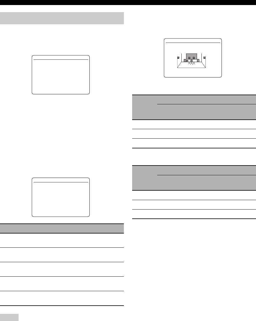
Using SET MENU
4 Press
9
k / n repeatedly and then press
9
ENTER to select and enter the desired
Use the remote control to access and adjust each
menu.
parameter.
The following displays are examples where “SOUND
y
MENU” is selected.
• You can change the “SET MENU” parameters while this unit is
reproducing sound.
3 SOUND MENU
• If you press
R
PARAMETER during the “SET MENU”
operation, the “SET MENU” operation is canceled.
.
A)EQUALIZER
B)LFE LEVEL
• Press
0
RETURN to return to the previous menu level.
C)DYNAMIC RANGE
D)LIPSYNC
E)EXTD SUR.
1 Set the operation mode selector to
F
AMP
[]/[]:
[
p
Up/Down
[ENTER]:
Enter
and then press
H
SET MENU to enter “SET
MENU”.
The top “SET MENU” display appears in the OSD.
5 Press
9
k / n repeatedly and then press
9
ENTER to select and enter the desired
2 Press
9
k / n to select “MANUAL SETUP”.
submenu.
The following display is an example where “LFE
SET MENU
LEVEL” is selected.
;AUTO SETUP
.
;MANUAL SETUP
;SIGNAL INFO
B)LFE LEVEL
.
SPEAKER;;;;;;0dB
HEADPHONE;;-20dB
[]/[]:
[
p
Up/Down
[ENTER]:
Enter
[]/[]:
[
p
Up/Down
OPERATION
[p]/[[]:
Adjust
ADVANCED
3 Press
9
ENTER to enter “MANUAL SETUP”.
The “MANUAL SETUP” display appears in the
OSD.
6 Press
9
k / n to select the desired parameter
and then
9
l / h to change the parameter
MANUAL SETUP
settings.
.
1 BASIC MENU
2 VOLUME MENU
•Press
9
h to increase the value.
3 SOUND MENU
4 INPUT MENU
•Press
9
l to decrease the value.
5 OPTION MENU
[]/[]:
[
p
Up/Down
[ENTER]:
Enter
7 Press
H
SET MENU to exit from “SET
MENU”.
English
75 En
Customizing this unit (MANUAL SETUP)
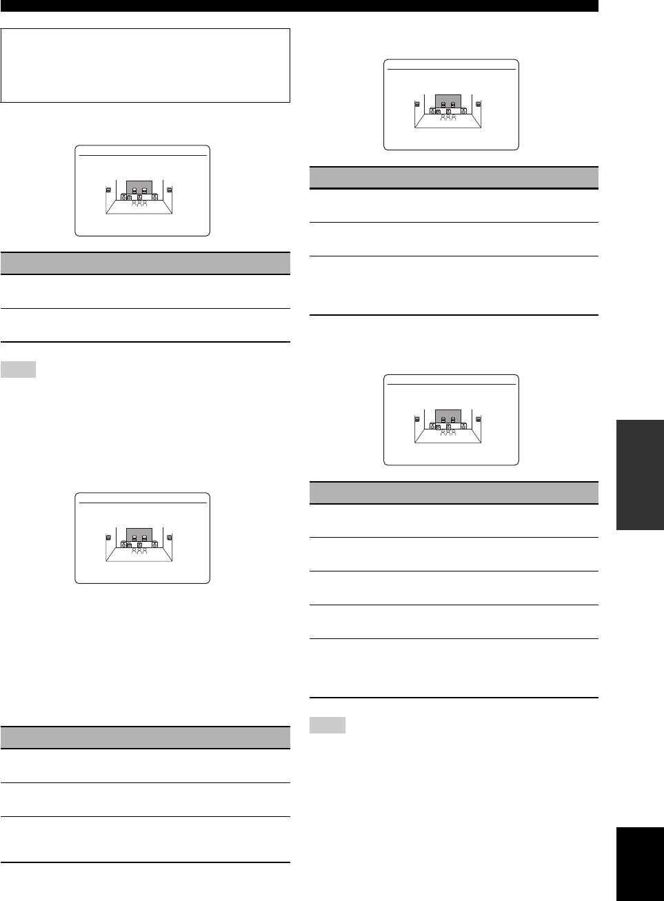
LFE/bass out LFE/BASS OUT
1 BASIC MENU
Use this feature to select the speakers that output the LFE
(low-frequency effect) and the low-frequency signals.
Use this feature to manually adjust the basic speaker
settings. Most of the “BASIC MENU” parameters are set
A)SPEAKER SET
automatically when you run the automatic setup.
LFE/BASS OUT
1 BASIC MENU
.
A)SPEAKER SET
B)SP LEVEL
C)SP DISTANCE
SWFR FRONT >BOTH
D)TEST TONE
[]/[]:
[
p
Up/Down
[ENTER]:
Enter
LFE signals output
Subwoofer(s) and speakers
y
Choice
Front
Other
Set “TEST TONE” to “ON” to output the test tone for the
Subwoofer(s)
speakers
speakers
“SPEAKER SET”, “SP LEVEL” and “SP DISTANCE”.
BOTH
Output No output No output
■ Speaker settings A)SPEAKER SET
SWFR
Output No output No output
y
To select the desired parameter, press
9
k / n repeatedly.
FRONT
No output Output No output
Extra speaker assignment EXTRA SP ASSIGN
Selects the function of the speakers connected to the
Low-frequency signals output
EXTRA SP terminals.
Subwoofer(s) and speakers
Choice
X
A)SPEAKER SET
Front
Other
Subwoofer(s)
X
speakers
speakers
X
EXTRA SP ASSIGN
X
ZONE2 >FRONT B
X
ZONE B PRESENCE
NONE
BOTH
*1 *2 *3
X
X
X
SWFR
*4 *3 *3
X
XXXX[]/[]:Up/DownXXXXX
ZONE2 SET
[
p
XXXX[p]/[[]:EnterXXXXXXX
Not Available
X
FRONT
No output *1 *3
*1
Output(s) the low-frequency signals of the front
Choice Descriptions
channels and other speakers set to “SMALL”.
*2
ZONE2
Select this setting when you use the Zone 2
Always output the low-frequency signals of the front
speakers (see page 104).
channels.
*3
Output the low-frequency signals if the speakers are set
FRONT B
Select this setting when you use another front
to “LARGE”.
speaker system in the main zone (see page 43).
*4
Outputs the low-frequency signals of the speakers set to
ZONE B
Select this setting when you use another front
“SMALL” or “NONE”.
speaker system in another room (see page 43).
PRESENCE
Select this setting when you use the presence
speakers (see page 13).
NONE
Select this setting when you do not use the
EXTRA SP terminals.
Notes
• This parameter shares the value with the “EXTRA SP
ASSIGN” parameter in “AUTO SETUP” (see page 33).
• If you select “ON” in “BI-AMP” (see page 109), you cannot
select “PRESENCE” or “ZONE2” in “EXTRA SP ASSIGN”.
• After changing the “EXTRA SP ASSIGN” setting, carry out
“AUTO SETUP” again (see page 32).
76 En
Customizing this unit (MANUAL SETUP)
Surround left/right speakers SUR. L/R SP
Measure for the speaker size
The woofer section of a speaker is
A)SPEAKER SET
– 16 cm (6.5 in) or larger: large
SUR. L/R SP
– smaller than 16 cm (6.5 in): small
Front speakers FRONT SP
NONE >SMALL LARGE
A)SPEAKER SET
FRONT SP
Choice Descriptions
LARGE
Select this setting when the surround speakers
are large.
SMALL >LARGE
SMALL
Select this setting when the surround speakers
are small.
Choice Descriptions
NONE
Select this setting when you do not use the
surround speakers. This unit is set to the Virtual
LARGE
Select this setting when the front speakers are
CINEMA DSP mode (see page 51), and “SUR.B
large.
L/R SP” is automatically set to “NONE”.
SMALL
Select this setting when the front speakers are
small.
Surround back left/right speakers
SUR.B L/R SP
Note
A)SPEAKER SET
When “LFE/BASS OUT” is set to “FRONT”, you can select only
SUR.B L/R SP
“LARGE” in “FRONT SP”. If the value of “FRONT SP” is set to
other than “LARGE” in advance, this unit change the value to
“LARGE” automatically.
OPERATION
ADVANCED
SMLx1 >SMLx2 LRGx1
Center speaker CENTER SP
Choice Descriptions
A)SPEAKER SET
CENTER SP
LRGx1
Select this setting when the single surround back
speaker is large.
LRGx2
Select this setting when the surround back left
and right speakers are Large.
NONE >SMALL LARGE
SMLx1
Select this setting when the single surround back
speaker is small.
When the center speaker is large:
SMLx2
Select this setting when the surround back left
Select “LARGE” (large).
and right speakers are small.
When the center speaker is small:
NONE
Select this setting when you do not use the
Select “SMALL” (small).
surround back speakers. The surround back
channel signals are directed to the surround left
When you do not use the center speaker:
and right speakers.
Select “NONE” (none). The center channel signals are
directed to the front left and right speakers.
Note
Choice Descriptions
If the Dolby TrueHD audio signals are input and “SUR.B L/R
LARGE
Select this setting when the center speaker is
SP” is set to “NONE”, the left and right surround back channels
large.
are not directed to the surround left and right speakers.
SMALL
Select this setting when the center speaker is
small.
NONE
Select this setting when you do not use the center
speaker. The center channel signals are directed
English
to the front left and right speakers.
77 En
Customizing this unit (MANUAL SETUP)
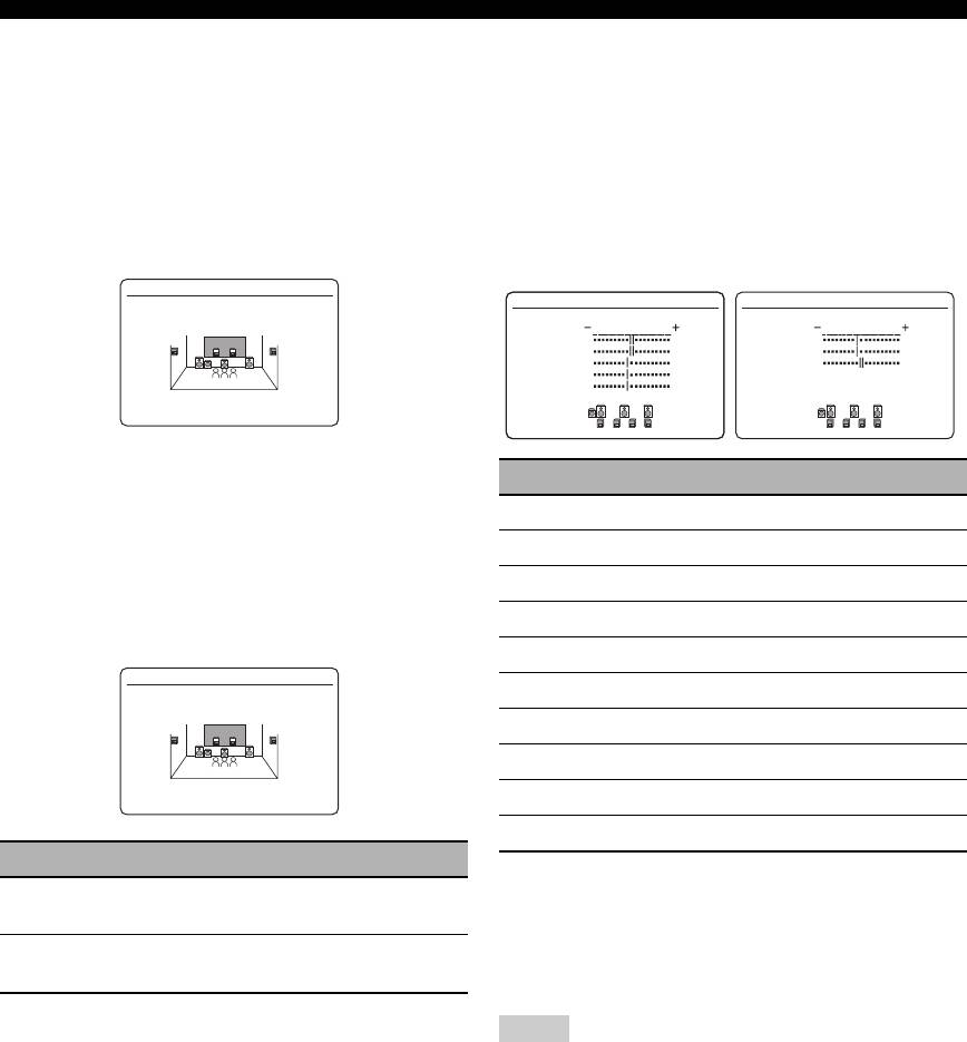
Bass cross over CROSS OVER
■ Speaker level B)SP LEVEL
Use this feature to select the crossover frequency of all the
Use this feature to manually balance the speaker levels
speakers set to “SML” (or “SMALL”) in “SPEAKER
between the front left or surround left speakers and each
SET” (see page 76). All frequencies below the selected
speaker selected in “SPEAKER SET” (see page 76).
frequency will be sent to the subwoofer(s) or front
Control range: –10.0 dB to +10.0 dB
speakers depending on the setting of “LFE/BASS OUT”
Control step: 0.5 dB
in “SPEAKER SET” (see page 76).
Initial setting:
Choices: 40Hz, 60Hz, 80Hz, 90Hz, 100Hz, 110Hz,
FR.L/FR.R/SWFR/PR.L/PR.R: 0 dB
120Hz, 160Hz, 200Hz
CNTR/SUR.L/SUR.R/SBL/SBR: –1.0 dB
A)SPEAKER SET
B)SP LEVEL 1/2
B)SP LEVEL 2/2
CROSS OVER
.
FR.L
.
SBL
FR.R
SBR
CNTR
SWFR
SUR.L
SUR.R
FREQ;;;;80Hz
y
If your subwoofer can adjust the output volume and the crossover
SP LEVEL Adjusted speaker
frequency, set the volume to about half way (or slightly less) and
FR.L
Front left speaker
set the crossover frequency to the maximum.
FR.R
Front right speaker
Subwoofer phase SUBWOOFER PHASE
CNTR
Center speaker
Use this feature to switch the phase of your subwoofer if
SUR.L
Surround left speaker
bass sounds are lacking or unclear.
SUR.R
Surround right speaker
A)SPEAKER SET
SBL
Surround back left speaker
SUBWOOFER PHASE
SBR
Surround back right speaker
SWFR
Subwoofer
>NORMAL REVERSE
PR.L
Presence left speaker
PR.R
Presence right speaker
Choice Functions
y
NORMAL
Does not change the phase of your subwoofer.
• If your subwoofer can adjust the output volume and the
(normal)
crossover frequency, set the volume to about half way (or
slightly less) and set the crossover frequency to the maximum.
REVERSE
Sets the phase of your subwoofer to reverse.
• Set “TEST TONE” to “ON” to output the test tone for the
(reverse)
“SPEAKER LEVEL” setting (see page 79).
Notes
• The available speaker channels differ depending on the setting
of the speakers.
• Instead of “SBL” and “SBR”, “SB” is displayed if “SUR. B L/R
SP” is set to either “SMLx1” or “LRGx1” (see page 77).
78 En
Customizing this unit (MANUAL SETUP)
■ Speaker distance C)SP DISTANCE
■ Test tone D)TEST TONE
Use this feature to manually adjust the distance of each
Turns the test tone output on or off for the “SPEAKER
speaker and the delay applied to the respective channel.
SET”, “SP LEVEL”, and “SP DISTANCE” settings.
Ideally, each speaker should be the same distance from the
main listening position. However, this is not possible in
D)TEST TONE
most home situations. Thus, a certain amount of delay
>OFF ON
must be applied to the sound from each speaker so that all
sounds will arrive at the listening position at the same
time.
[p]/[[]:
Select
[ENTER]:
Return
C)SP DISTANCE 1/2
C)SP DISTANCE 2/2
.
UNIT;;;;;;meters
FRONT L;;;;3.00m
.
SBL;;;;;;;;2.40m
Choice Functions
FRONT R;;;;3.00m
SBR;;;;;;;;2.40m
CENTER;;;;;2.60m
SWFR;;;;;;;3.00m
SUR. L;;;;;2.40m
PRNS L;;;;;3.00m
OFF
This unit does not output the test tone for the
SUR. R;;;;;2.40m
PRNS R;;;;;3.00m
“SPEAKER SET”, “SP LEVEL”, and “SP
[]/[]:
[
p
Up/Down
[]/[]:
[
p
Up/Down
DISTANCE” settings.
[p]/[[]:
Select
[p]/[[]:
Adjust
ON
This unit outputs the test tone for the
“SPEAKER SET”, “SP LEVEL”, and “SP
Unit for the speaker distance adjustment UNIT
DISTANCE” settings.
Initial setting:
y
[U.S.A. and Canada models]: feet (ft)
If you use a handheld sound pressure level meter, hold at arm’s
[Other models]: meters (m)
length and point upwards so that the meter is in the listening
Choice Functions
position. With the meter set to the 70 dB scale and to C SLOW,
calibrate each speaker to 75 dB.
meters (m)
Adjusts speaker distances in meters.
Note
feet (ft)
Adjusts speaker distances in feet.
This function is automatically turned off if you exit from “BASIC
OPERATION
ADVANCED
MENU”.
Speaker distances
Control range: 0.30 to 24.00 m (1.0 to 80.0 ft)
Control step: 0.10 m (0.5 ft)
Initial setting:
FRONT L/FRONT R/SWFR/PRNS L/
PRNS R: 3.00 m (10.0 ft)
CENTER: 2.60 m (8.5 ft)
SUR. L/SUR. R/SBL/SBR: 2.40 m (8.0 ft)
SP DISTANCE Adjusted speaker
FRONT L
Front left speaker
FRONT R
Front right speaker
CENTER
Center speaker
SUR. L
Surround left speaker
SUR. R
Surround right speaker
SBL
Surround back left speaker
SBR
Surround back right speaker
SWFR
Subwoofer
PRNS L
Presence left speaker
PRNS R
Presence right speaker
Notes
English
• The available speaker channels differ depending on the setting
of the speakers.
• Instead of “SBL” and “SBR”, “SUR.B” is displayed if “SUR.B
L/R SP” is set to either “SMLx1” or “LRGx1” (see page 77).
79 En

Customizing this unit (MANUAL SETUP)
Adaptive DSP level ADAPTIVE DSP LEVEL
2 VOLUME MENU
Use this feature to make fine adjustments of the DSP
effect level (see page 65) automatically in conjunction
Use this menu to manually adjust the various volume
with the volume level.
settings.
Choice Functions
2 VOLUME MENU
AUTO
Adjusts the DSP effect level in conjunction with
.
ADAPTIVE DRC;;;;OFF
the volume level.
ADAPTIVE DSP
LEVEL;;;;OFF
MUTE TYPE;;;;;;FULL
OFF
Does not adjust the DSP effect level
MAX VOL.;;;;+16.5dB
INIT. VOL.;;;;;;OFF
automatically.
[]/[]:
[
p
Up/Down
[p]/[[]:
Select
Note
Adaptive dynamic range control
Even if you set “ADAPTIVE DSP LEVEL” to “AUTO”, this unit
does not change but the fine-tunes the specified value of “DSP
ADAPTIVE DRC
LEVEL” (see page 65).
Use this feature to adjust the dynamic range in
conjunction with the volume level. This feature is useful
Muting type MUTE TYPE
when you are listening at lower volumes or at night. When
Use this feature to adjust how much the mute function
“ADAPTIVE DRC” is set to “AUTO”, this unit controls
reduces the output volume (see page 45).
the dynamic range as follows:
– If the VOLUME setting is low:
Choice Functions
the dynamic range is narrow
FULL
Mutes all the audio output.
– If the VOLUME setting is high:
the dynamic range is wide
–20dB
Reduces the current volume by 20 dB.
Maximum volume MAX VOL.
AUTO
Use this feature to set the maximum volume level in the
AUTO
main zone. This feature is useful to avoid the unexpected
loud sound by mistake. For example, the original volume
OFF
OFF
Output level
Output level
range is –80.0 dB to +16.5 dB. However, when “MAX
Input level
Input level
VOL.” is set to –5.0 dB, the volume range becomes
VOLUME: low VOLUME: high
–80.0 dB to –5.0 dB.
Control range: –30.0 dB to +15.0 dB, +16.5 dB
Choice Functions
Control step: 5.0 dB
AUTO
Adjusts the dynamic range automatically.
Notes
OFF
Does not adjust the dynamic range automatically.
• When this unit is in the auto setup procedure, the volume level
is automatically set to 0 dB regardless of the current “MAX
y
VOL.” setting.
• You can also adjust the dynamic range of the bitstream signal
• The “MAX VOL.” setting takes priority over the initial volume
sources by using “DYNAMIC RANGE” in “SOUND MENU”
setting. For example, if “INI.VOL.” is set to –20.0 dB and
(see page 82).
“MAX VOL.” is set to –30.0 dB, the volume level is
• This function is also useful for listening with your headphones.
automatically set to –30.0 dB when you turn on the power of
this unit next time.
Note
• Use “MAX VOL.” in “ZONE SET” to set the initial volume
The adaptive dynamic range control feature does not function
level in Zone 2.
when this unit is in the Pure Direct mode (see page 52).
Initial volume INIT. VOL.
Use this feature to set the volume level of the main zone
when the power of this unit is turned on.
Choices: OFF, MUTE, –80.0 dB to +16.5 dB
Control step: 0.5 dB
Note
The “MAX VOL.” setting takes priority over the initial volume
setting.
80 En
Customizing this unit (MANUAL SETUP)
Graphic equalizer GEQ
3 SOUND MENU
Use this feature to match the tonal quality of the center,
surround L/R and surround back L/R, and surround back
Use this feature to adjust the audio parameters.
speakers with that of the front L/R speakers. You can
adjust 7 frequency bands (63 Hz, 160 Hz, 400 Hz, 1 kHz,
3 SOUND MENU
2.5 kHz, 6.3 kHz, 16 kHz).
.
A)EQUALIZER
Control range: –6.0 dB to +6.0 dB
B)LFE LEVEL
C)DYNAMIC RANGE
Control step: 0.5 dB
D)LIPSYNC
E)EXTD SUR.
[]/[]:
[
p
Up/Down
A)EQUALIZER 1/2
A)EQUALIZER 2/2
[ENTER]:
Enter
TEST >OFF ON
TEST >OFF ON
.
CHANNEL;;;;FRONT L
CHANNEL;;;;FRONT L
63Hz 0dB
.
2.5kHz 0dB
■ Equalizer A)EQUALIZER
160Hz 0dB
6.3kHz 0dB
400Hz 0dB
16kHz 0dB
1kHz 0dB
Use this feature to select the parametric equalizer or the
[]/[]:
[
p
Up/Down
[]/[]:
[
p
Up/Down
Select
graphic equalizer.
[p]/[[]:
[p]/[[]:
Adjust
Equalizer type select EQ TYPE SELECT
y
Use this feature to select the type of equalizer.
Press
9
k / n to select a frequency band and
9
l / h to adjust
the selected frequency band.
A)EQUALIZER
EQ TYPE SELECT
Note
AUTO PEQ >GEQ OFF
[NATURAL]
The “GEQ” parameter can be adjusted only when “GEQ” is
selected in “EQ TYPE SELECT”.
[p]/[[]:
Select
[ENTER]:
Enter
Test tone TEST
Use this feature to make adjustments of “GEQ” while
Choice Functions
listening to a test tone. To select “TEST”, press
9
k / n
OPERATION
ADVANCED
repeatedly in the graphic equalizer screen.
AUTO PEQ
Uses the parametric equalizer adjusted in
“AUTO SETUP” (see page 33).
A)EQUALIZER 1/2
GEQ
Adjusts the built-in 7-frequency band graphic
equalizer so that the tonal quality of the speakers
.
TEST >OFF ON
CHANNEL;;;;FRONT L
matches. Press
9
ENTER to display the graphic
63Hz 0dB
equalizer screen.
160Hz 0dB
400Hz 0dB
1kHz 0dB
OFF
Deactivates the equalizing feature.
[]/[]:
[
p
Up/Down
[p]/[[]:
Select
y
Currently applied parametric equalizer type (see page 33) appears
Choice Functions
under “AUTO PEQ”.
OFF
Does not output test tones and output the
Note
currently selected source component.
You can select “AUTO PEQ” only when you carry out “AUTO
ON
Outputs test tones from the selected speakers.
SETUP” in advance (see page 32). In this case, “AUTO PEQ” is
automatically selected as the default setting.
English
81 En

Customizing this unit (MANUAL SETUP)
■ Low-frequency effect level
■ Dynamic range C)DYNAMIC RANGE
B)LFE LEVEL
Use this feature to select the amount of dynamic range
Use this feature to adjust the output level of the LFE (low-
compression to be applied to your speakers or
frequency effect) channel according to the capacity of
headphones. This setting is effective only when this unit is
your subwoofer or headphones. The LFE channel carries
decoding bitstream signals.
low-frequency special effects which are only added to
certain scenes. This setting is effective when the input
C)DYNAMIC RANGE
signal contains the LFE signal.
SPEAKER;;;;;;;;;MAX
.
HEADPHONE;;;;;;;MAX
Control range: –20 to 0 dB
Control step: 1 dB
[]/[]:
[
p
Up/Down
B)LFE LEVEL
[p]/[[]:
Select
.
SPEAKER;;;;;;0dB
HEADPHONE;;;;0dB
Speakers SPEAKER
Adjusts the dynamic range compression for the speakers.
[]/[]:
[
p
Up/Down
[p]/[[]:
Adjust
Headphones HEADPHONE
Adjusts the dynamic range compression for the
Speakers SPEAKER
headphones.
Adjusts the speaker LFE level.
Choice Functions
Headphones HEADPHONE
MIN/AUTO
• MIN: Adjusts the dynamic range to narrow
Adjusts the headphone LFE level.
when this unit is decoding bitstream signals
(except Dolby TrueHD).
• AUTO: Adjusts the dynamic range according
Note
to the instruction of the input source signals
Depending on the settings of “LFE/BASS OUT” (see page 76),
when this unit is decoding Dolby TrueHD
some signals may not be output at the SUBWOOFER PRE OUT
signals.
jack.
STD
Adjusts the dynamic range to medium. When
this unit is decoding Dolby TrueHD signals, the
dynamic range control is always active
regardless of the instruction of the input source
signals.
MAX
Preserves the greatest amount of dynamic range.
82 En

Customizing this unit (MANUAL SETUP)
■ Audio and video synchronization
■ Extended surround E)EXTD SUR.
(lip sync)
D)LIPSYNC
Use this feature to enjoy 6.1/7.1-channel playback for
Use this feature to adjust the audio and video
multi-channel sources using the Dolby Pro Logic IIx,
synchronization.
Dolby Digital EX, or DTS-ES decoders by using the
connected surround back speakers.
D)LIPSYNC
.
HDMI AUTO;;;;;;OFF
E)EXTD SUR.
AUTO;;;;;;;;;---ms
(offset;;;---ms)
EXTD SUR.;;;;;;AUTO
MANUAL;;;;;;;;;0ms
[]/[]:
[
p
Up/Down
[p]/[[]:
Select
[p]/[[]:
Select
[ENTER]:
Return
HDMI automatic lip sync mode HDMI AUTO
If the connected video monitor is connected to the HDMI
Choice Functions
OUT jack of this unit and compatible with the automatic
AUTO
Activates the optimum decoder to play back
audio and video synchronization function (automatic lip
signals in 6.1/7.1 channels when this unit
sync), this unit adjusts the audio and video
recognizes a signal flag being input.
synchronization automatically. Use this feature to activate
PLIIxMovie
Plays back Dolby Digital or DTS signals in 7.1
or deactivate the automatic lip sync.
channels using the Pro Logic IIx movie decoder.
Choices: ON, OFF
PLIIxMusic
Plays back Dolby Digital or DTS signals in 6.1/
If the connected video monitor is compatible
7.1 channels using the Pro Logic IIx music
with the automatic lip sync:
decoder.
Select “ON”. Use “AUTO” to make fine adjustments of
EX/ES
Plays back Dolby Digital or DTS signals in 6.1/
the audio and video synchronization.
7.1 channels using the Dolby Digital EX or DTS-
ES decoder.
If the video monitor is not compatible with the
OFF
Does not use any decoders to create 6.1/7.1
automatic lip sync or you do not want to use
OPERATION
ADVANCED
channels.
the automatic lip sync:
Select “OFF”. Use “MANUAL” to adjust the audio and
video synchronization.
Auto delay AUTO
Use this feature to make fine adjustments of the audio and
video synchronization when you set “HDMI AUTO” to
“ON”.
Control range: 0 to 240 ms
Control step: 1 ms
y
“offset” indicates the difference between the value of the audio
delay that this unit sets automatically and the value of the audio
delay that you set in “AUTO”. This unit stores the value of
“offset” and applies the value to other automatic lip sync
compatible video monitors.
Manual delay MANUAL
Use this feature to adjust the delay of the sound output
manually to synchronize audio with video images when
you set “HDMI AUTO” to “OFF”.
Control range: 0 to 240 ms
Control step: 1 ms
English
83 En
Customizing this unit (MANUAL SETUP)
Input/output assignment
4 INPUT MENU
I/O ASSIGNMENT
Use this feature to assign the input/output jacks according
Use this menu to adjust the parameters of each input
to the component to be used if the initial settings of this
source.
unit do not correspond to your needs. Change the
parameter to reassign the respective jacks and effectively
4 INPUT MENU 1/2
4 INPUT MENU 2/2
connect more components.
.
A) PHONO
.
H) DOCK
Once the input/output jacks are reassigned, you can select
B) TUNER
I) BLUETOOTH
C) CD
J) DVR
D) MD/CD-R
K) VCR
the corresponding component by using the
R
INPUT
E) DVD
L) MULTI CH
F) DTV/CBL
selector on the front panel (or the input selector buttons
G) V-AUX
[]/[]:
[
p
Up/Down
[]/[]:
[
p
Up/Down
(
5
) on the remote control).
[ENTER]:
Enter
[ENTER]:
Enter
J)DVR
Input source Parameter
.
COMPONENT IN;;;[B]
*
COAXIAL IN;;;;NONE
OPTICAL IN;;;;NONE
B)TUNER INPUT RENAME
OPTICAL OUT;;;NONE
HDMI IN;;;;;;;;[3]
VOL. TRIM
Current( DTV/CBL )
[p]/[[]:
Select
L)MULTI CH INPUT RENAME
[ENTER]:
Enter
VOL. TRIM
BGV
INPUT CH
y
• “NONE” appears in the OSD when any input source is not
FRONT
assigned to the input/output jack.
A)PHONO
I/O ASSIGNMENT
• Set “OPTICAL OUT” to “(1)” for the digital recording
C)CD
INPUT RENAME
component that you connect to the DIGITAL OUTPUT jack.
D)MD/CD-R
VOL. TRIM
• You cannot select a specific item more than once for the same
E)DVD
DECODER MODE
type of jack.
F)DTV/CBL
• An asterisk (*) appears to the right of the input/output jack
G)V-AUX
names that have been changed from their previous settings.
J)DVR
• The currently assigned input source for the selected input/
K)VCR
output jack appears in the OSD (“Current( DTV/CBL )” in the
display example above).
H)DOCK INPUT RENAME
VOL. TRIM
STANDBY CHARGE
I)BLUETOOTH INPUT RENAME
VOL. TRIM
START PAIRING
Note
Some parameters described above may not be available for all
input sources and some parameters are only available for specific
input sources.
84 En

Customizing this unit (MANUAL SETUP)
Input rename INPUT RENAME
Decoder mode DECODER MODE
Use this feature to change the name of the input source
Use this feature to switch the decoder activation mode.
that appears in the OSD and in the front panel display.
When you select “DTS” and digital audio signals are
input, this unit always activates the DTS decoder and only
J)DVR
plays back the DTS digital audio signals.
INPUT RENAME
C)CD
DVR . DVR
I/O ASSIGNMENT
[p]/[[]:
Position
INPUT RENAME
[ ]/[ ]:
[
p
Character
VOL. TRIM;;;;;0.0dB
[ENTER]:
Enter
.
DECODER MODE;;;AUTO
[RETURN]:
Return
[]/[]:
[
p
Up/Down
[p]/[[]:
Select
1 Press
9
l / h to place the “_” (underscore)
under the space or the character you want to
Choice Functions
edit.
AUTO
Automatically detects digital audio signal input
types and selects the appropriate decoder.
2 Press
9
k / n to select the character you
DTS
Activates the DTS decoder and plays back only
want to use and then press
9
l / h to move
DTS digital audio signals when digital audio
signals are input.
to the next space.
Notes
Note
• You can use up to 9 characters for each input.
“DECODER MODE” is only available when the digital audio
• Press
9
n to change the character in the following order,
input jacks (HDMI, OPTICAL, and/or COAXIAL) are assigned
or press
9
k to go in the reverse order:
to the selected input source.
A to Z, 0 to 9, a to z, symbols (#, *, –, +, etc.), space.
Charge on standby STANDBY CHARGE
OPERATION
ADVANCED
3 Repeat steps 1 through 2 to rename each
Use this feature to select whether this unit charges the
input source.
battery of the stationed iPod or not when this unit is in the
standby mode.
4 Press
9
ENTER to complete.
Choice Functions
AUTO
Charges the battery of the stationed iPod when
Volume trim VOL. TRIM
this unit is turned on and in the standby mode.
Use this feature to adjust the level of the signal input at
OFF
Charges the battery of the stationed iPod only
each jack. This feature is useful if you want to balance the
when this unit is turned on.
level of each input source to avoid sudden changes in
volume when switching between input sources.
Control range: –6.0 dB to +6.0 dB
Control step: 0.5 dB
Initial setting: 0.0 dB
B)TUNER
INPUT RENAME
.
VOL. TRIM;;;;+6.0dB
[]/[]:
[
p
Up/Down
[p]/[[]:
Adjust
y
This parameter also affects the signals output at the audio ZONE
OUT jacks.
English
85 En
Customizing this unit (MANUAL SETUP)
Start pairing START PAIRING
Choice Functions
Use this feature to start pairing the connected Yamaha
Bluetooth adapter (such as YBA-10, sold separately) with
LAST
Automatically selects the last selected video
source as the background video source.
your Bluetooth component. For details about the pairing,
refer to “Pairing the Bluetooth™ adapter and your
DVD, DTV/
Selects the corresponding input source as the
Bluetooth™ component” on page 62.
CBL, DVR,
background video source.
VCR, V-AUX
To ensure security, a time limit of 8 minutes is set for
OFF
Does not play the video source in the
the pairing operation. You are recommended to read
background.
and fully understand all the instructions before starting.
Input channels INPUT CH
Use this setting to select the number of channels input
1 Press
9
ENTER to start pairing.
from an external decoder (see page 25).
The connected Bluetooth adapter starts searching
Choices: 6CH, 8CH
Bluetooth components. “Searching...” appears in the
video monitor.
L)MULTI CH
INPUT RENAME
VOL. TRIM;;;;;0.0dB
2 Check that the Bluetooth component detects
BGV;;;;;;;;;;;;LAST
.
INPUT CH;;;;;;;;6CH
the Bluetooth adapter.
If the Bluetooth component the Bluetooth adapter,
[]/[]:
[
p
Up/Down
[ENTER]:
Select
“YBA-10 YAMAHA” (example) appears in the
Bluetooth device list.
If the connected component outputs discrete
3 Select the Bluetooth adapter in the Bluetooth
6-channel audio signals.
device list and then enter the pass key
Select “6CH”.
“0000” on the Bluetooth component.
If the connected component outputs discrete
Once this unit completes the pairing successfully,
8-channel audio signals.
“Pairing completed” appears.
Select “8CH”. Also set “FRONT” (see below) to the
y
analog audio jacks at which the front left and right
To cancel the pairing, press
0
RETURN to exit from
channel signals output from the connected component
“START PAIRING”.
are input.
4 Press
0
RETURN to exit from “START
Front left and right channels input jack FRONT
PAIRING”.
If you selected “8CH” in “INPUT CH”, you can select the
analog audio jacks at which the front left and right channel
Notes
signals output from the connected external decoder is
input.
• If the connected Bluetooth adapter cannot find any Bluetooth
components, “Not found” appears.
Choices: CD, MD/CD-R, DVD, DTV/CBL, DVR, VCR,
• If a Bluetooth adapter is not connected to this unit, “No
V-AUX
Bluetooth Adapter” appears.
L) MULTI CH
Multi-channel input BGV BGV
INPUT RENAME
VOL. TRIM;;;;;0.0dB
Use this feature to select the video source played in the
BGV;;;;;;;;;;;;LAST
INPUT CH;;;;;;;;8CH
background of the sources input at the MULTI CH INPUT
.
FRONT;;;;;;;;;;;DVD
jacks.
[]/[]:
[
p
Up/Down
[ENTER]:
Select
L)MULTI CH
INPUT RENAME
VOL. TRIM;;;;;0.0dB
Note
.
BGV;;;;;;;;;;;;LAST
INPUT CH;;;;;;;;6CH
“FRONT” parameter appears only when you set “INPUT CH” to
“8CH”.
[]/[]:
[
p
Up/Down
[ENTER]:
Select
86 En

Customizing this unit (MANUAL SETUP)
Amplifier function OSD display time OSD-AMP
5 OPTION MENU
Use this feature to set the amount of time to display the
status information screen after you perform a certain
Use this menu to adjust the optional system parameters.
operation.
5 OPTION MENU
Choice Functions
.
A)DISPLAY SET
ON
Displays the OSD unceasingly during an
B)VIDEO SET
C)MEMORY GUARD
operation.
D)INIT. CONFIG
E)HDMI SET
F)ZONE2 SET
10S
Turns off the OSD 10 seconds after you perform
[]/[]:
[
p
Up/Down
a certain operation.
[ENTER]:
Enter
30S
Turns off the OSD 30 seconds after you perform
a certain operation.
■ Display settings A)DISPLAY SET
Front panel display scroll FL SCROLL
Note
Use this feature to set the mode to display the iPod menu
Use “VIDEO” of “INIT” in “ADVANCED SETUP” to set “OSD
(such as song title or channel name) in the front panel
SHIFT” to the factory presets (see page 109).
display.
Choice Functions
A)DISPLAY SET
.
DIMMER;;;;;;;;;;;;0
CONT
Continuous mode.
OSD SHIFT;;;;;;;;+5
Select this to display the operation status in the
OSD-SOURCE;;;;;;30S
OSD-AMP;;;;;;;;;30S
front panel display in a continuous manner.
FL SCROLL;;;;;;CONT
ONCE
Scroll-once mode.
[]/[]:
[
p
Up/Down
[p]/[[]:
Adjust
Select this to display the operation status in the
front panel display by the first 14 alphanumeric
characters after scrolling all characters once.
Dimmer DIMMER
OPERATION
ADVANCED
Use this feature to adjust the brightness of the front panel
display.
Control range: – 4 to 0
Control step: 1
•Press
9
l to make the front panel display dimmer.
•Press
9
h to make the front panel display brighter.
OSD shift OSD SHIFT
Use this feature to adjust the vertical position of the OSD.
Control range: –5 (downward) to +5 (upward)
Control step: 1
Initial setting: 0
•Press
9
l to lower the position of the OSD.
•Press
9
h to raise the position of the OSD.
Source feature OSD display time OSD-SOURCE
Use this feature to set the amount of time to display the
iPod menu in the OSD after you perform a certain
operation.
Choice Functions
ON
Displays the OSD unceasingly during an
operation.
10S
Turns off the OSD 10 seconds after you perform
a certain operation.
30S
Turns off the OSD 30 seconds after you perform
English
a certain operation.
87 En
Customizing this unit (MANUAL SETUP)
■ Video settings B)VIDEO SET
■ Memory guard C)MEMORY GUARD
Use this feature to prevent accidental changes to sound
Note
field program parameter and other system settings.
Use “VIDEO” of “INIT” in “ADVANCED SETUP” to set the
parameters in “VIDEO SET” to the factory presets (see
C)MEMORY GUARD
page 109).
>OFF ON
B)VIDEO SET
.
VIDEO CONV.;;;;;;ON
[p]/[[]:
Select
[ENTER]:
Return
[]/[]:
[
p
Up/Down
Choice Functions
[p]/[[]:
Select
OFF
Turns off the “MEMORY GUARD” feature.
ON
Protects:
Video conversion VIDEO CONV.
– sound field program parameters
Use this feature to set whether to convert the video signals
– “AUTO SETUP” items
– all speaker levels
input at the VIDEO, S VIDEO, and COMPONENT
– “MANUAL SETUP” items
VIDEO jacks.
Choice Functions
Notes
ON
Converts composite, S-video, and component
• You can change the following parameters even if “MEMORY
video signals interchangeably and up-converts
GUARD” is set to “ON”:
composite, S-video, and component video
– “EXTD SUR.” in “SOUND MENU” (see page 83)
signals to HDMI video signals.
– “DECODER MODE” in “INPUT MENU” (see page 85)
– “MEMORY GUARD”
OFF
Does not convert any signals.
• When “MEMORY GUARD” is set to “ON”, “ ” appears at the
G
top right of the “SET MENU” screen.
Notes
• You can change the settings of “SUR.” in the sound field
• This unit does not convert 480 line video signals and 576 line
program parameter screen (see page 69) even if “MEMORY
video signals interchangeably.
GUARD” is set to “ON”.
• The analog component video signals with 480i (NTSC)/576i
(PAL) of resolution are converted into the S-video or composite
video signals and output at the S VIDEO MONITOR OUT and
VIDEO MONITOR OUT jacks.
• The converted video signals are only output at the MONITOR
OUT jacks. When recording a video source, you must make the
same type of video connections between each component.
• When composite video or S-video signals from a VCR are
converted into component video signals, the picture quality may
suffer depending on your VCR.
• Unconventional signals input at the composite video or S-video
jacks cannot be converted or may be output abnormally. In such
cases, set “VIDEO CONV.” to “OFF”.
88 En
Customizing this unit (MANUAL SETUP)
■ Initial configuration D)INIT. CONFIG
■ HDMI set E)HDMI SET
Use this feature to select the settings of the audio input
Use this feature to select the component to play back
jack select, active decoders and extended surround when
HDMI audio signals.
you turn on this unit.
E)HDMI SET
D)INIT. CONFIG
S. AUDIO;;;;;RX-V663
.
AUDIO SELECT;;AUTO
DECODER MODE;;AUTO
EXTD SUR.;;;;;AUTO
[p]/[[]:
Select
[ENTER]:
Return
[p]/[[]:
Select
[ENTER]:
Return
Support audio S.AUDIO
Audio select AUDIO SELECT
Use this feature to select whether to play back HDMI
Use this feature to designate the default audio input jack
audio signals on this unit or on another HDMI component
select setting (see page 44) for the input sources connected
connected to the HDMI OUT jack on the rear panel of this
to the DIGITAL INPUT jacks when you turn on the power
unit.
of this unit.
Choice Functions
Choice Functions
RX-V663
Plays back HDMI audio signals on this unit. The
HDMI audio signals input at the HDMI input
AUTO
Automatically detects the type of input signals
and selects the appropriate audio input jack
jacks of this unit are not output to the HDMI
select setting.
component connected to the HDMI OUT jack on
the rear panel of this unit.
LAST
Automatically selects the last input jack select
setting used for the connected input source.
OTHER
Plays back HDMI audio signals on another
HDMI component connected to the HDMI OUT
jack.
Decoder mode DECODER MODE
OPERATION
ADVANCED
Use this feature to designate the default decoder mode
Notes
(see page 85) for the input sources connected to the
DIGITAL INPUT jacks when you turn on the power of
• This unit transmits audio and video signals input at the HDMI
this unit.
input jacks to the HDMI out jack only when this unit is turned
on even if “S.AUDIO” is set to “OTHER”.
Choice Functions
• Available audio/video signals depend on the specification of the
connected video monitor. Refer to the instruction manual of
AUTO
Automatically detects the type of input signals
and select the appropriate decoder mode setting.
each connected component.
LAST
Automatically selects the last decoder mode
setting used for the connected input source.
Extended surround EXTD SUR.
Use this feature to designate the extended decoder mode
(see page 83) for the input sources connected to the
DIGITAL INPUT jacks when you turn on the power of
this unit.
Choice Functions
AUTO Automatically detects the digital audio input
signals and activates the appropriate decoder.
LAST Automatically selects the last decoder mode set
for “EXTD SUR.” in “SOUND MENU”.
English
89 En

Customizing this unit (MANUAL SETUP)
■ Zone 2 settings F)ZONE2 SET
F)ZONE2 SET
.
MAX VOL.;;;+16.5dB
INIT. VOL.;;;;;OFF
[]/[]:
[
p
Up/Down
[p]/[[]:
Adjust
Zone 2 Maximum volume MAX VOL.
Use this feature to set the maximum volume level in the
Zone 2.
Control range: –30.0 dB to +15.0 dB, +16.5 dB
Control step: 5.0 dB
Notes
• The “MAX VOL.” setting takes priority over the “INI.VOL.”
setting. For example, when “INI.VOL.” is set to –20.0 dB and
then “MAX VOL.” is set to –30.0 dB, the volume level is
automatically set to –30.0 dB when you turn on the power of
this unit next time.
• The “MAX VOL.” setting does not affect the output level at the
“ZONE 2 OUT” jacks.
Zone 2 Initial volume INI.VOL.
Use this feature to set the volume level of Zone 2 when the
power of this unit is turned on.
Choices: OFF, MUTE, –80.0 dB to +16.5 dB
Control step: 0.5 dB
Notes
• The “MAX VOL.” setting takes priority over the “INI.VOL.”
setting.
• When you select “FRONT B”, “PRNS”, “Zone B”, or “NONE”
in “EXTRA SP ASSIGN” (see page 76), “Zone 2 SP Not
Assigned” appears in the OSD and the “ZONE2 SET”
parameter is not available.
• The “INI.VOL.” setting does not affect the output level at the
“ZONE 2 OUT” jacks.
90 En
Оглавление
- Caution: Read this before operating your unit.
- Contents
- Features
- Notice
- Getting started
- Quick start guide
- Connections
- Optimizing the speaker setting for your listening room (YPAO)
- Selecting the SCENE templates
- Playback
- Sound field programs
- Using audio features
- FM/AM tuning
- Radio Data System tuning (Europe and Russia models only)
- Using iPod™
- Using Bluetooth™ components
- Recording
- Advanced sound configurations
- Customizing this unit (MANUAL SETUP)
- Remote control features
- Using multi-zone configuration
- Advanced setup
- Troubleshooting
- Resetting the system
- Glossary
- Sound field program information
- Specifications
- Index
- Предупреждение: Внимательно изучите это перед использованием аппарата.
- Содержание
- Описание
- Уведомление
- Начало работы
- Краткое руководство пользователя
- Подключения
- Оптимизация настройки колонок для комнаты для прослушивания (YPAO)
- Выборе шаблонов SCENE
- Воспроизведение
- Программы звукового поля
- Использование аудиофункций
- Настройка радиопрограмм диапазона ЧМ/AM
- Функция настройки Системы Радиоданных (Только модели для Европы и России)
- Использование iPod™
- Использование компонентов Bluetooth™
- Запись
- Дополнительные конфигурации звучания
- Настройка данного аппарата (MANUAL SETUP)
- Функции пульта ДУ
- Использование многозонной конфигурации
- Дополнительные настройки
- Возможные неисправности и способы по их устранению
- Перезагрузка системы
- Справочник
- Информация программы звукового поля
- Технические характеристики
- Предметный указател


