Yamaha RX-V663 Black: Connections
Connections: Yamaha RX-V663 Black
CONNECTIONS
Connections
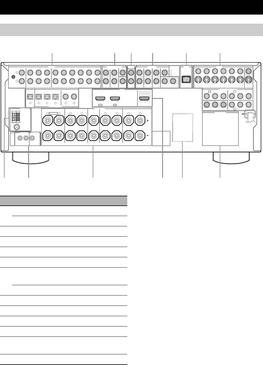
Rear panel
AUDIO MULTI CH INPUT PRE OUT DOCK VIDEO
SINGLE CENTERCENTERFRONT (8CH)
VIDEO
L
GND
R
IN
MD/
OUT
SUB
12
S VIDEO
PHONO
CD
(PLAY)
CD-R
(REC)
DVD
DTV/CBL DVR VCR
OUTININ OUT
SURROUND
WOOFER
SUR. BACKSURROUND
DVDSUBWOOFERFRONTSB (8CH) ZONE 2
DTV/CBL
DVR
VCR
OUTININ OUT
MONITOR
HDMI
OUT
OUT
DVD
COMPONENT VIDEO
DTV/CBL
P
R
A B
P
B
Y
P
R
P
B
Y
MD/CD-R MD/CD-R
DVD
DVDCDDTV/CBL
321
4
65
DTV/CBLDVD
DIGITAL
OPTICAL COAXIAL
IN2IN1
OUT
OUTPUT
DIGITAL INPUT
ANTENNA
SPEAKERS
FRONT B/ZONE B/
C
DVRMONITOR OUT
ZONE 2/PRESENCE
CENTERFRONT A
SURROUND BACK/BI-AMPSURROUND
AM
R
EXTRA SP
L
R
L
R
L
R
L
AC OUTLETS
GND
FM
75Ω
UNBAL.
REMOTE
TRIGGER
OUT
+12V
IN OUT
15mA MAX.
SINGLE
8
TRIGGER OUT jack
This is control expansion jack for custom installation.
10 En
78 9 0A B
123456
Name Page
1 AUDIO jacks
21
DIGITAL INPUT/OUTPUT jacks
17-23
2 MULTI CH INPUT jacks
25
3 ZONE2 OUT jacks
103
4 PRE OUT jacks
24
5 DOCK terminal
25
6 Video component jacks
17-22
(VIDEO and S VIDEO)
COMPONENT VIDEO jacks
17-22
7 ANTENNA terminals
27
8 REMOTE IN/OUT jacks
26
9 Speaker terminals
11-16
0 HDMI jacks
18
A VOLTAGE SELECTOR
4
(Asia and General models only)
B AC OUTLET(S)
28
Connections
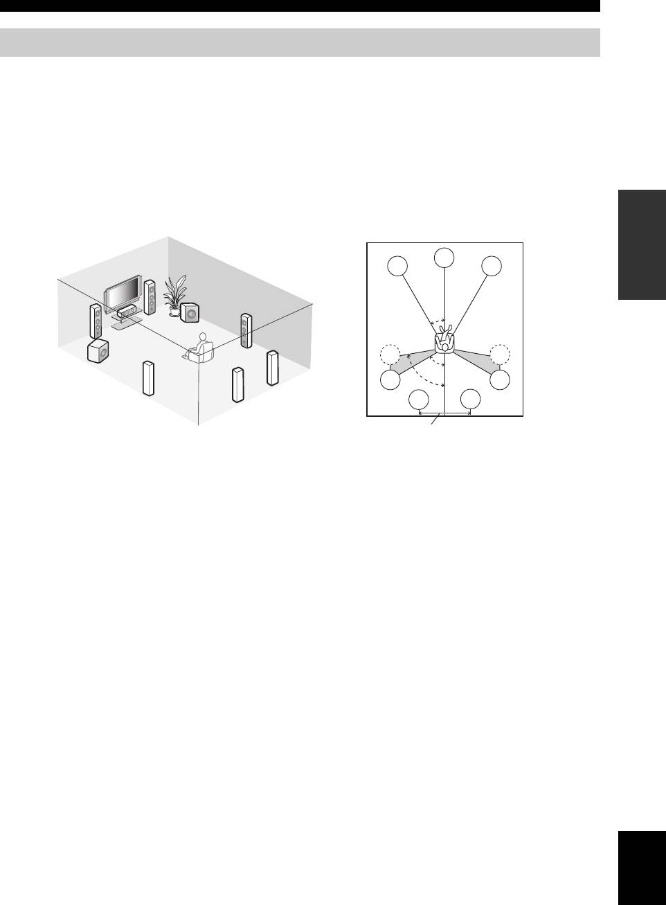
Placing speakers
The speaker layout below shows the speaker setting we recommend. You can use it to enjoy the CINEMA DSP and
multi-channel audio sources.
■ 7.1-channel speaker layout
7.1-channel speaker layout is highly recommended for playback the sound of high definition audio formats (Dolby
TrueHD, DTS-HD Master Audio, etc.) as well as the conventional audio sources with sound field programs. See page 14
for connection information.
y
We recommend that you also add the presence speakers for the effect sounds of the CINEMA DSP sound field program. See page 13 for
PREPARATION
details.
C
FL
FR
FR
SW
FL
SR
30˚
C
SL
SR
SL
SW
60˚
SBR
SL
SR
80˚
SBL
SBR
SBL
30 cm (12 in) or more
Speaker indications
FL/FR: Front left/right
C: Center
SL/SR: Surround left/right
SBL/SBR: Surround back left/right
SW: Subwoofer
Front left and right speakers
The front speakers are used for the main source sound plus effect sounds. Place these speakers at an equal distance from the
ideal listening position. The distance of each speaker from each side of the video monitor should be the same.
Center speaker
The center speaker is for the center channel sounds (dialog, vocals, etc.). If for some reason it is not practical to use a
center speaker, you can do without it. Best results, however, are obtained with the full system.
Surround left and right speakers
The surround speakers are used for effect and surround sounds.
Surround back left and right speakers
The surround back speakers supplement the surround speakers and provide more realistic front-to-back transitions.
Subwoofer(s)
The use of a subwoofer with a built-in amplifier, such as the Yamaha Active Servo Processing Subwoofer System, is
effective not only for reinforcing bass frequencies from any or all channels, but also for reproducing the high fidelity
sound of the LFE (low-frequency effect) channel included in Dolby Digital and DTS sources. You can connect one or
two subwoofer(s) to this unit. When you use two subwoofers, you can enjoy deeper bass sound. The position of the
subwoofer is not so critical, because low bass sounds are not highly directional. But it is better to place the subwoofer
English
near the front speakers. Turn it slightly toward the center of the room to reduce wall reflections.
y
When you use two subwoofers, select the same type of the subwoofer as another and set these subwoofers as same sound characteristics.
Place each subwoofer at the same distance from the listening position. The signal output at the SUBWOOFER PRE OUT 2 jack is the
same as the one output at the SUBWOOFER PRE OUT 1 jack.
11 En
Connections
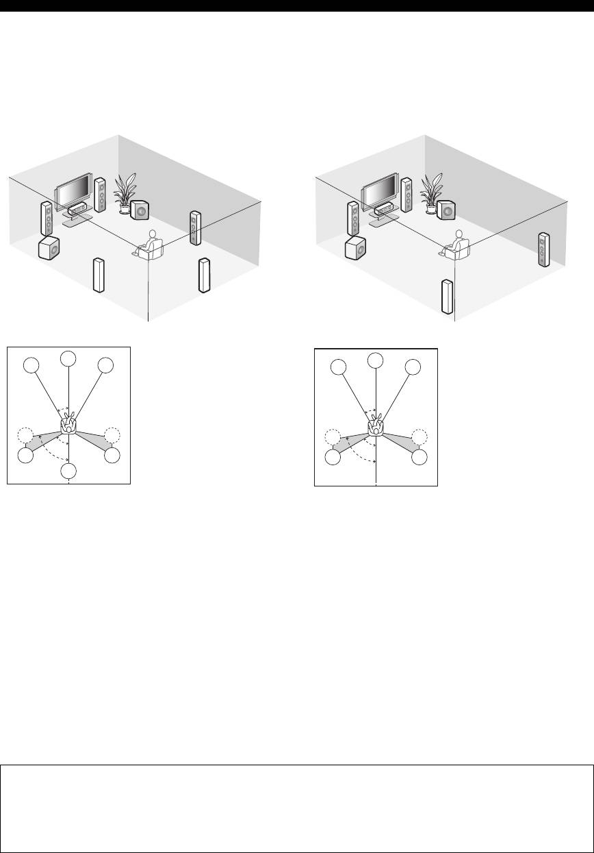
■ 6.1-channel speaker layout
■ 5.1-channel speaker layout
See page 14 for connection information.
See page 14 for connection information.
y
y
We recommend that you also add the presence speakers for the
We recommend that you also add the presence speakers for the
effect sounds of the CINEMA DSP sound field program. See
effect sounds of the CINEMA DSP sound field program. See
page 13 for details.
page 13 for details.
FR
FR
SW
SW
FL
SR
FL
C
C
SR
SL
SW
SW
SB
SL
C
Speaker indications
C
Speaker indications
FL
FR
FL
FR
FL/FR: Front left/right
FL/FR: Front left/right
C: Center
C: Center
30˚
30˚
SL/SR: Surround left/right
SL/SR: Surround left/right
SB: Surround back
SW: Subwoofer
SL
SR
SW: Subwoofer
SL
SR
60˚
60˚
SL
SR
80˚
SL
SR
80˚
SB
Front left and right speakers
Front left and right speakers
Center speaker
Center speaker
Surround left and right speakers
Subwoofer(s)
Subwoofer(s)
The functions and settings of each speaker are the same as
The functions and settings of each speaker are the same as
those for the 7.1-channel speaker layout (see page 11).
those for the 7.1-channel speaker layout (see page 11).
Surround left and right speakers
Surround back speaker
Connect the surround speakers to the SURROUND
Connect a single surround speakers to the SURROUND
speaker terminals even if you place the surround speakers
BACK SINGLE speaker terminal and place the single
behind the listening position. For the smooth and
surround back speaker behind the listening position. The
unbroken sound field behind the listening position, place
surround back left and right channel signals are mixed
the surround left and right speakers farther back compared
down and output at the single surround back speaker when
with the placement in the 7.1-channel speaker layout. The
you set “SUR.B L/R SP” to “SMLx1” or “LRGx1” (see
surround back channel signals are directed to the surround
page 77).
left and right speakers when “SUR.B L/R SP” is set to
“NONE” (see page 77).
For other speaker combinations
You can enjoy multi-channel sources with sound field programs by using a speaker combination other than the 7.1/
6.1/5.1-channel speaker combinations.
Use the automatic setup feature (see page 32) or set the “SPEAKER SET” parameters in “MANUAL SETUP” (see
page 76) to output the surround sounds at the connected speakers.
12 En
Connections
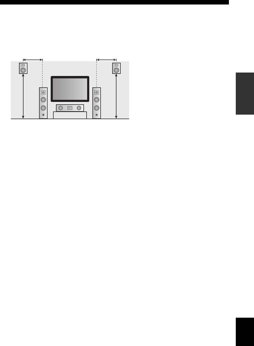
■ Using presence speakers
The presence speakers supplement the sound from the front and surround back speakers with extra ambient effects
produced by the sound field programs (see page 48). You can adjust the vertical position of dialogues with using the
presence speakers (see page 65).
To use the presence speakers, connect the speakers to the EXTRA SP terminal (see page 14) and set “EXTRA SP
ASSIGN” to “PRESENCE” (see pages 33 and 76).
0.5 to 1 m (1 to 3 ft)
0.5 to 1 m (1 to 3 ft)
Speaker indications
FL: Front left
PRPL
FR: Front right
PREPARATION
C: Center
PL: Front presence left
1.8 m
1.8 m
PR: Front presence right
(6 ft) or
FL
FR
(6 ft) or
higher
higher
C
English
13 En
Connections
Connecting speakers
Be sure to connect the left channel (L), right channel (R), “+” (red) and “–” (black) properly. If the connections are faulty,
this unit cannot reproduce the input sources accurately.
Caution
• Before connecting the speakers, make sure that the AC power plug is disconnected from the AC wall outlet.
• Do not let the bare speaker wires touch each other or let them touch any metal part of this unit. This could damage
this unit and/or the speakers. If the speaker wires are short-circuited, “CHECK SP WIRES” appears in the front
panel display when you turn on this unit.
• Use the magnetically shielded speakers. If this type of speaker still creates interference with the monitor, place the
speakers away from the monitor.
• If you are to use 6 ohm speakers, be sure to set “SP IMP.” to “6Ω MIN” before using this unit (see page 28). 4 ohm
speakers can be also used as the front speakers. For details about the speaker impedance setting, see page 106.
Note
A speaker cord is actually a pair of insulated cables running side by side. Cables are colored or shaped differently, perhaps with a stripe,
groove or ridge. Connect the striped (grooved, etc.) cable to the “+” (red) terminals of this unit and your speaker. Connect the plain cable
to the “–” (black) terminals.
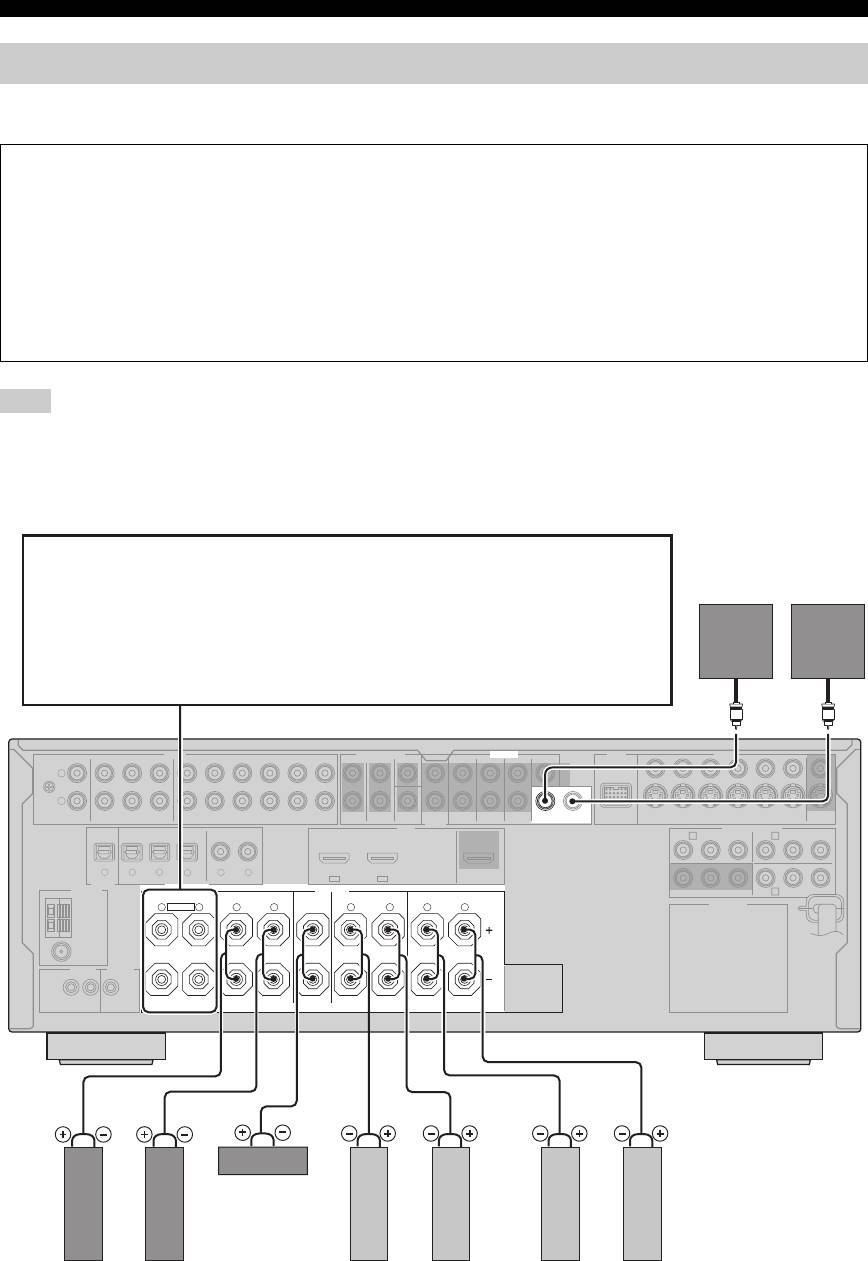
■ For the 7.1-channel speaker setting
EXTRA SP terminals
Connect the alternative front speaker system (FRONT B), front speaker systems in another room
Subwoofers
(ZONE B), presence speakers, or Zone 2 speakers. To select the function of the speakers connected
(optional)
to the EXTRA SP terminals, set the “EXTRA SP ASSIGN” parameter in “SOUND MENU” (see
page 76).
y
You can also select the function of the speakers connected to the EXTRA SP terminals in “AUTO
SETUP” (see page 33).
AUDIO MULTI CH INPUT PRE OUT DOCK VIDEO
SINGLE CENTERCENTERFRONT (6CH)
VIDEO
L
GND
R
IN
MD/
OUT
SUB
1 2
S VIDEO
PHONO
CD
(PLAY)
CD-R
(REC)
DVD
DTV/CBL DVR VCR
OUTININ OUT
SURROUND
WOOFER
SUR. BACKSURROUND
DVDSUBWOOFERFRONTSB (8CH) ZONE 2
DTV/CBL
DVR
VCR
OUTININ OUT
MONITOR
OUT
OUT
HDMI
DVD
COMPONENT VIDEO
DTV/CBL
P
R
A B
P
B
Y
P
R
P
B
Y
MD/CD-R MD/CD-R
DVD
DVDCDDTV/CBL
321
4
65
DTV/CBLDV D
OPTICAL COAXIAL
IN2IN1
OUT
DIGITAL
OUTPUT
DIGITAL INPUT
ANTENNA
SPEAKERS
FRONT B/ZONE B/
C
DVRMONITOR OUT
ZONE 2/PRESENCE
CENTERFRONT A
SURROUND BACK/BI-AMPSURROUND
AC OUTLETS
AM
R
EXTRA SP
L
R
L
R
L
R
L
GND
FM
75Ω
UNBAL.
REMOTE
TRIGGER
OUT
+12V
IN OUT
15mA MAX.
SINGLE
Center speaker
Right
Left
Right
Left
Right
Left
Front speakers
Surround speakers
Surround back speakers
(FRONT A)
14 En
Connections
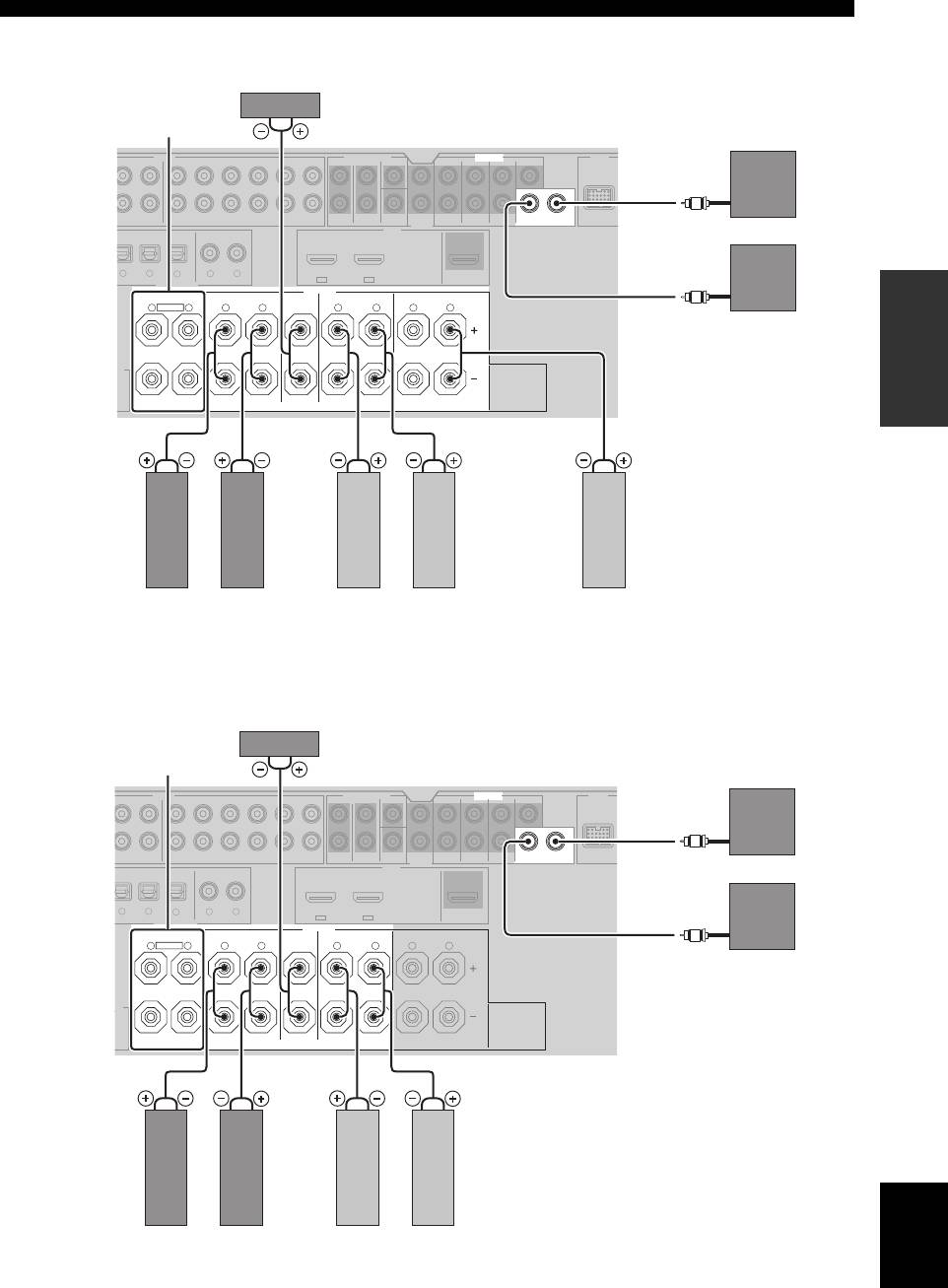
■ For the 6.1-channel speaker setting
AUDIO MULTI CH INPUT PRE OUT DOCK
HDMI
DIGITAL INPUT
PREPARATION
Surround back speaker
■ For the 5.1-channel speaker setting
English
15 En
E
SINGLE CENTERCENTERFRONT (6CH)
SUB
12
DVD
SURROUND
WOOFER
SUR. BACKSURROUND
SUBWOOFERFRONTSB (8CH) ZONE 2
OUT
DVD
DVDCDDTV/CBL
OUT
OPTICAL COAXIAL
SPEAKERS
CENTERFRONT A
SURROUND BACK/BI-AMPSURROUND
R
SINGLE
A
DTV/CBLDVD
FRONT B/ZONE B/
ZONE 2/PRESENCE
X.
D
MD/
CD-R
/CD-R
I
N
L
Center speaker
EXTRA SP terminals
(see page 14)
(optional)
OUT
AY )
(REC)
DTV/CBL DVR VCR
OUTININ OUT
Subwoofers
32
4
65
IN2IN1
R
EXTRA SP
L
R
L
R
L
R
L
LeftRight
LeftRight
Left (SINGLE)
Front speakers
Surround speakers
(FRONT A)
AUDIO MULTI CH INPUT PRE OUT DOCK
HDMI
DIGITAL INPUT
E
R
T
SINGLE CENTERCENTERFRONT (6CH)
SUB
12
DVD
SURROUND
WOOFER
SUR. BACKSURROUND
SUBWOOFERFRONTSB (8CH) ZONE 2
OUT
DVD
DVDCDDTV/CBL
OUT
OPTICAL COAXIAL
SPEAKERS
CENTERFRONT A
SURROUND BACK/BI-AMPSURROUND
SINGLE
A
DTV/CBLDVD
FRONT B/ZONE B/
ZONE 2/PRESENCE
X.
D
Center speaker
EXTRA SP terminals
(see page 14)
(optional)
IN
MD/
OUT
LAY)
CD-R
(REC)
DTV/CBL DVR VCR
OUTININ OUT
Subwoofers
/CD-R
32
4
65
IN2IN1
R
EXTRA SP
L
R
L
R
L
R
L
LeftRight
LeftRight
Front speakers
Surround speakers
(FRONT A)
Connections
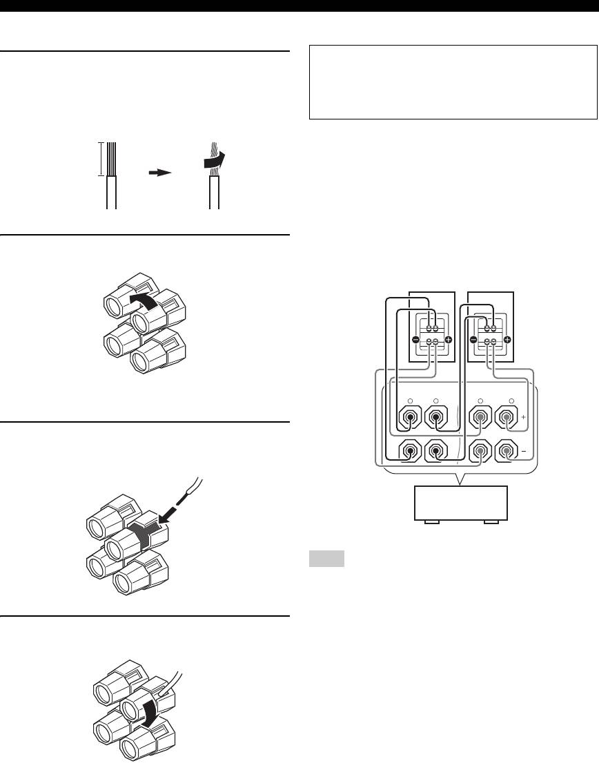
■ Connecting the speaker cable
■ Using bi-amplification connections
Caution
1 Remove approximately 10 mm (0.4 in) of
Remove the shorting bars or bridges of your speakers
insulation from the end of each speaker
to separate the LPF (low pass filter) and HPF (high
cable and then twist the exposed wires of the
pass filter) crossovers.
cable together to prevent short circuits.
This unit allows you to make bi-amplification connections
to one speaker system. Check if your speakers support bi-
10 mm (0.4 in)
amplification.
To make the bi-amplification connections, use the FRONT
and SURROUND BACK/BI-AMP terminals as shown
below. To activate the bi-amplification connections, set
“BI-AMP” to “ON” in “ADVANCED SETUP” (see
page 109).
2 Loosen the knob.
Front speakers
Right
Left
Red: positive (+)
FRONT A
SURROUND BACK/
BI-AMP
Black: negative (–)
R
L
R
SINGLE
L
3 Insert one bare wire into the hole on the side
of each terminal.
This unit
Note
When you make the conventional connection, make sure that the
shorting bars are put into the terminals appropriately. Refer to the
instruction manuals of the speakers for details.
4 Tighten the knob to secure the wire.
16 En

Connections
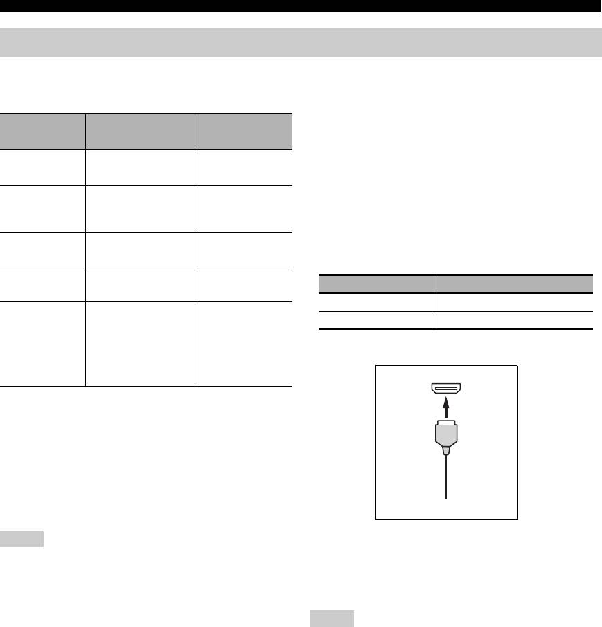
Information on jacks and cable plugs
Connect one of the type of the audio jack(s) and/or video jack(s) that your input components are equipped with.
Audio jacks and cable plugs
Video jacks and cable plugs
AUDIO
DIGITAL
DIGITAL
COMPONENT VIDEO
L
R
COAXIAL
OPTICAL
VIDEO S VIDEO
YR P B P
(Yellow) (Green)(Blue)(Red)
PREPARATION
(Red)(White) (Orange)
O
S
V
L
R
C
P
R
PB
Y
Left and right
Coaxial
Optical
Composite
S-video
Component
analog audio
digital audio
digital
video cable
cable plug
video cable
cable plugs
cable plug
audio cable
plug
plugs
plug
■ Audio jacks
■ Video jacks
This unit has three types of audio jacks. Connection
This unit has three types of video jacks. Connection
depends on the availability of audio jacks on your other
depends on the availability of input jacks on your video
components.
monitor.
AUDIO jacks
VIDEO jacks
For conventional analog audio signals transmitted via left
For conventional composite video signals transmitted via
and right analog audio cables. Connect red plugs to the
composite video cables.
right jacks and white plugs to the left jacks.
S VIDEO jacks
DIGITAL COAXIAL jacks
For S-video signals, separated into the luminance (Y) and
For digital audio signals transmitted via coaxial digital
chrominance (C) video signals transmitted on separate
audio cables.
wires of S-video cables.
DIGITAL OPTICAL jacks
COMPONENT VIDEO jacks
For digital audio signals transmitted via optical digital
For component video signals, separated into the
audio cables.
luminance (Y) and chrominance (P
B, PR) video signals
transmitted on separate wires of component video cables.
Note
y
You can use the digital jacks to input PCM, Dolby Digital and
This unit is equipped with the video conversion function. See
DTS bitstreams. When you connect components to both the
pages 19 and 88 for details.
COAXIAL and OPTICAL jacks, priority is given to the signals
input at the COAXIAL jack. Optical input jacks are compatible
with digital signals with up to 96 kHz of sampling frequency.
English
17 En
Connections
Information on HDMI™
■ HDMI signal compatibility
Video signals
This unit is compatible with the video signals of the
Audio signals
following resolutions:
Audio signal
Audio signal
Compatible
Video signal format
types
formats
media
– 480i/60 Hz
2ch Linear
2ch, 32-192 kHz,
CD, DVD-Video,
– 576i/50 Hz
PCM
16/20/24 bit
DVD-Audio, etc.
– 480p/60 Hz
– 576p/50 Hz
Multi-ch
8ch, 32-192 kHz,
DVD-Audio, Blu-
Linear PCM
16/20/24 bit
ray Disc, HD DVD,
– 720p/60 Hz, 50 Hz
etc.
– 1080i/60 Hz, 50 Hz
– 1080p/60 Hz, 50 Hz, 24 Hz
DSD 2/5.1ch,
SA-CD, etc.
2.8224 MHz, 1 bit
Default input assignment of HDMI input jacks
Bitstream Dolby Digital,
DVD-Video, etc.
HDMI input jack Assigned input source
DTS
IN1 DVD
Bitstream (High
Dolby TrueHD,
Blu-ray Disc,
IN2 DTV/CBL
definition audio)
Dolby Digital Plus,
HD DVD, etc.
DTS-HD Master
■ HDMI jack and cable plug
Audio, DTS-HD High
Resolution Audio,
DTS Express
HDMI
y
• If the input source component can decode the bitstream audio
signals of audio commentaries, you can play back the audio
sources with the audio commentaries mixed down by using the
following connections:
– multi-channel analog audio input (see page 25)
– DIGITAL INPUT OPTICAL (or COAXIAL)
• Refer to the supplied instruction manuals of the input source
HDMI cable plug
component, and set the component appropriately.
y
Notes
• We recommend that you use an HDMI cable shorter than 5
• When CPPM copy-protected DVD-Audio is played back, video
meters (16 feet) with the HDMI logo printed on it.
and audio signals may not be output depending on the type of
• Use a conversion cable (HDMI jack
↔ DVI-D jack) to connect
the DVD player.
this unit to other DVI components.
• This unit is not compatible with HDCP-incompatible HDMI or
DVI components.
Notes
• To decode audio bitstream signals on this unit, set the input
• Do not disconnect or connect the cable or turn off the power of
source component appropriately so that the component outputs
the HDMI components connected to the HDMI OUT jack of
the bitstream audio signals directly (does not decode the
this unit while data is being transferred. Doing so may disrupt
bitstream signals on the component). Refer to the supplied
playback or cause noise.
instruction manuals for details.
• If you turn off the power of the video monitor connected to the
• This unit is not compatible with the audio commentary features
HDMI OUT jack via a DVI connection, this unit may fail to
(for example, the special audio contents downloaded via Internet)
establish the connection to the component.
of Blu-ray Disc or HD DVD. This unit does not play back the
• The analog video signals input at the composite video, S-video
audio commentaries of the Blu-ray Disc or HD DVD contents.
and component video jacks can be digitally up-converted to be
output at the HDMI OUT jack. Set “VIDEO CONV.” to “ON”
in “MANUAL SETUP” (see page 88) to activate this feature.
18 En
Connections
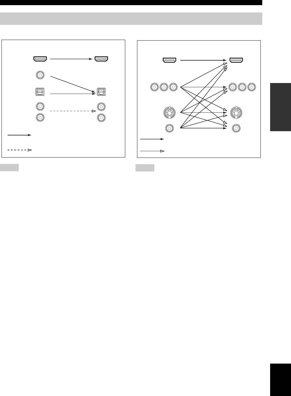
Audio and video signal flow
■ Audio signal flow
■ Video signal flow
OutputInput
OutputInput
HDMI
HDMI
DIGITAL AUDIO
(COAXIAL)
COMPONENT
VIDEO
PREPARATION
DIGITAL AUDIO
(OPTICAL)
AUDIO
S VIDEO
VIDEO
Digital output
Through
Analog output
Video conversion ON (see page 88)
Notes
Notes
• 2-channel as well as multi-channel PCM, Dolby Digital and
• When the video signals are input at the HDMI, COMPONENT
DTS signals input at one of the HDMI IN jacks can be output at
VIDEO, S VIDEO, and VIDEO jacks, the priority order of the
the HDMI OUT jack only when “S.AUDIO” is set to “OTHER”
input signals is as follows:
(see page 89).
1. HDMI
• Audio signals input at the HDMI IN jacks are not output at the
2. COMPONENT VIDEO
AUDIO output and DIGITAL OUTPUT jacks.
3. S VIDEO
4. VIDEO
• Digital video signals input at one of the HDMI IN jacks cannot
be output from analog video output jacks.
• The analog component video signals with
480i (NTSC)/576i (PAL) of resolution are converted to the
S-video or composite video signals and output at the S VIDEO
MONITOR OUT and VIDEO MONITOR OUT jacks.
• The analog component video signals with 1080p of resolution
are only output at the COMPONENT VIDEO MONITOR OUT
jacks.
English
19 En
Connections
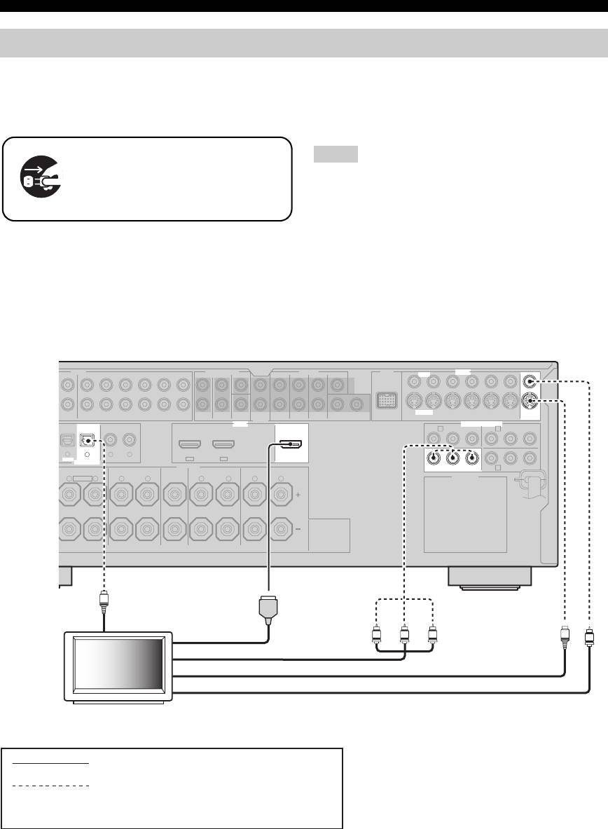
Connecting a TV monitor or projector
Connect your TV (or projector) to the HDMI OUT jack,
• When you use the internal tuner of the TV as the input source,
the COMPONENT VIDEO MONITOR OUT jacks, the
connect the digital or analog audio output jacks of the TV and
digital or analog audio input jacks of this unit. Refer to
S VIDEO MONITOR OUT jack or the VIDEO
“Connecting a set-top box” on page 22 for connecting
MONITOR OUT jack of this unit.
information.
Make sure that this unit and other
Notes
components are unplugged from the
• If a video monitor is connected to this unit via a DVI
AC wall outlets.
connection, you may not take full advantage of the HDMI
features.
• Some video monitors connected to this unit via a DVI
connection fail to recognize the HDMI audio/video signals
y
being input if they are in the standby mode. In this case, the
• You can choose to play back HDMI audio signals on this unit or
HDMI indicator flashes irregularly.
on another HDMI component connected to the HDMI OUT
• If the connected video monitor is compatible with the automatic
jack of this unit. Use the “S.AUDIO” parameter in “OPTION
audio and video synchronization feature (automatic lip sync
MENU” to select the component to play back HDMI audio
feature), this unit adjusts the audio and video timing
signals (see page 89).
automatically (see page 83). Connect the video monitor to the
HDMI OUT jack of this unit to use the feature.
AUDIO MULTI CH INPUT PRE OUT DOCK VIDEO
SINGLE CENTERCENTERFRONT (6CH)
VIDEO
SUB
12
S VIDEO
DVD
SURROUND
WOOFER
SUR. BACKSURROUND
DVDSUBWOOFERFRONTSB (8CH) ZONE 2
DTV/CBL
DVR
VCR
OUTININ OUT
HDMI
OUT
DVD
COMPONENT VIDEO
DTV/CBL
DVD
DVDCDDTV/CBL
DTV/CBLDVD
OUT
OPTICAL COAXIAL
DIGITAL INPUT
SPEAKERS
FRONT B/ZONE B/
DVRMONITOR OUT
ZONE 2/PRESENCE
SURROUND BACK/BI-AMPSURROUNDCENTERFRONT A
AC OUTLETS
20 En
D
/
OUT
-R
(REC)
DTV/CBL DVR VCR
OUTININ OUT
MONITOR
OUT
P
R
A B
P
B
Y
P
R
P
B
Y
3
4
65
IN2IN1
C
R
EXTRA SP
L
R
L
R
L
R
L
O
Optical out
HDMI in
Y
PRPB
S
V
Component video in
S-video in
Video in
TV (or projector)
indicates recommended connections
indicates alternative connections
(One for the video connection, and one for the
audio connection)
Connections
Connecting other components
• When “VIDEO CONV.” is set to “ON” (see page 88), the
converted video signals are output only at the MONITOR OUT
Make sure that this unit and other
jacks. To record a source, make the same type of video
components are unplugged from the
connections between each component.
AC wall outlets.
• To make a digital connection to a component other than the
default component assigned to each DIGITAL INPUT or
DIGITAL OUTPUT jack, select the corresponding setting for
“OPTICAL OUT”, “OPTICAL IN”, or “COAXIAL IN” in “I/O
Notes
ASSIGNMENT” (see page 84).
• If you connect your DVD player to both the DIGITAL INPUT
PREPARATION
• When “VIDEO CONV.” is set to “OFF” (see page 88), be sure
(OPTICAL) and the DIGITAL INPUT (COAXIAL) jacks,
to make the same type of video connections as those made for
priority is given to the signals input at the DIGITAL INPUT
your TV (see page 20). For example, if you connected your TV
(COAXIAL) jack.
to the VIDEO MONITOR OUT jack of this unit, connect your
other components to the VIDEO jacks.
■ Connecting a DVD player
DVD player
Optical out
S-video out
Coaxial out
Video out
Component video out
Audio out
HDMI out
RL
O
C
PR PB Y
V
S
AUDIO MULTI CH INPUT PRE OUT DOCK VIDEO
SINGLE CENTERCENTERFRONT (6CH)
VIDEO
L
GND
R
IN
MD/
OUT
SUB
12
S VIDEO
PHONO
CD
(PLAY)
CD-R
(REC)
DVD
DTV/CBL DVR VCR
OUTININ OUT
SURROUND
WOOFER
SUR. BACKSURROUND
DVDSUBWOOFERFRONTSB (8CH) ZONE 2
DTV/CBL
DVR
VCR
OUTININ OUT
MONITOR
OUT
OUT
HDMI
DVD
COMPONENT VIDEO
DTV/CBL
P
R
A B
P
B
Y
P
R
P
B
Y
MD/CD-R MD/CD-R
DVD
DVDCDDTV/CBL
21
3
4
65
DTV/CBLDVD
IN2IN1
OUT
DIGITAL
OPTICAL COAXIAL
OUTPUT
DIGITAL INPUT
ANTENNA
SPEAKERS
FRONT B/ZONE B/
C
DVRMONITOR OUT
ZONE 2/PRESENCE
SURROUND BACK/BI-AMPSURROUNDCENTERFRONT A
AM
R
EXTRA SP
L
R
L
R
L
R
L
AC OUTLETS
GND
FM
75Ω
UNBAL.
REMOTE
TRIGGER
OUT
+12V
IN OUT
15mA MAX.
indicates recommended connections
indicates alternative connections
(One for the video connection, and one for the
audio connection)
English
21 En
Connections
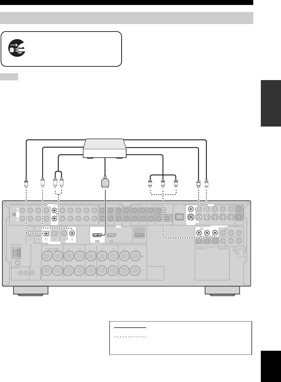
■ Connecting a DVD recorder, PVR or VCR
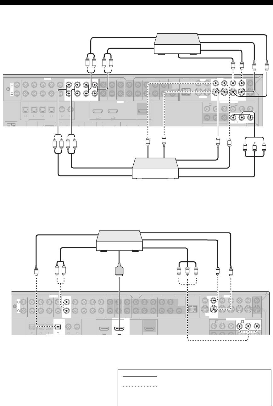
■ Connecting a set-top box
22 En
AC OUTLETS
AUDIO MULTI CH INPUT PRE OUT DOCK VIDEO
SINGLE CENTERCENTERFRONT (6CH)
VIDEO
L
GND
R
IN
MD/
OUT
OUTININ OUT
SUB
12
S VIDEO
PHONO
CD
(PLAY)
CD-R
(REC)
DVD
DTV/CBL DVR V CR
SURROUND
WOOFER
SUR. BACKSURROUND
DVDSUBWOOFERFRONTSB (8CH) ZONE 2
DTV/CBL
DVR
VCR
OUTININ OUT
MONITOR
OUT
OUT
HDMI
DVD
COMPONENT VIDEO
DTV/CBL
MD/CD-R MD/CD-R
DVD
DVDCDDTV/CBL
DTV/CBLDVD
OUT
DIGITAL
OPTICAL COAXIAL
OUTPUT
DIGITAL INPUT
ANTENNA
SPEAKERS
FRONT B/ZONE B/
DVRMONITOR OUT
ZONE 2/PRESENCE
SURROUND BACK/BI-AMPSURROUNDCENTERFRONT A
LLLL
321
4
65
IN2IN1
EXTRA SP
VCR
S-video out
Audio out
S-video in
Audio in
Video in
Video out
R LR L
V
V
S
S
P
R
AB
P
B
Y
P
R
P
B
Y
C
S-video out
Video out
S
V
S
L
R
L
R
V
Y PB PR
S-video in
Audio in
Video in
Audio out
Component video out
DVD recorder
or PVR
AUDIO MULTI CH INPUT PRE OUT DOCK VIDEO
SINGLE CENTERCENTERFRONT (6CH)
VIDEO
L
GND
R
IN
MD/
OUT
SUB
12
S VIDEO
PHONO
CD
(PLAY)
CD-R
(REC)
DVD
DTV/CBL DVR V CR
OUTININ OUT
SURROUND
WOOFER
SUR. BACKSURROUND
DVDSUBWOOFERFRONTSB (8CH) ZONE 2
DTV/CBL
DVR VCR
OUTININ OUT
MONITOR
OUT
OUT
HDMI
COMPONENT VIDEO
P
R
A B
DVD
DTV/CBL
P
B
Y
P
R
P
B
Y
MD/CD-R MD/CD-R
DVD
DVDCDDTV/CBL
G
OPTICAL COAXIAL
321
4
65
DTV/CBLDVD
IN2IN1
OUT
Satellite receiver, cable
TV receiver or HDTV
decoder
S-video out
Optical out
Video out
Audio out
Component video out
HDMI out
R L
O
Y PB PR
V
S
indicates recommended connections
indicates alternative connections
(One for the video connection, and one for the
audio connection)
Connections
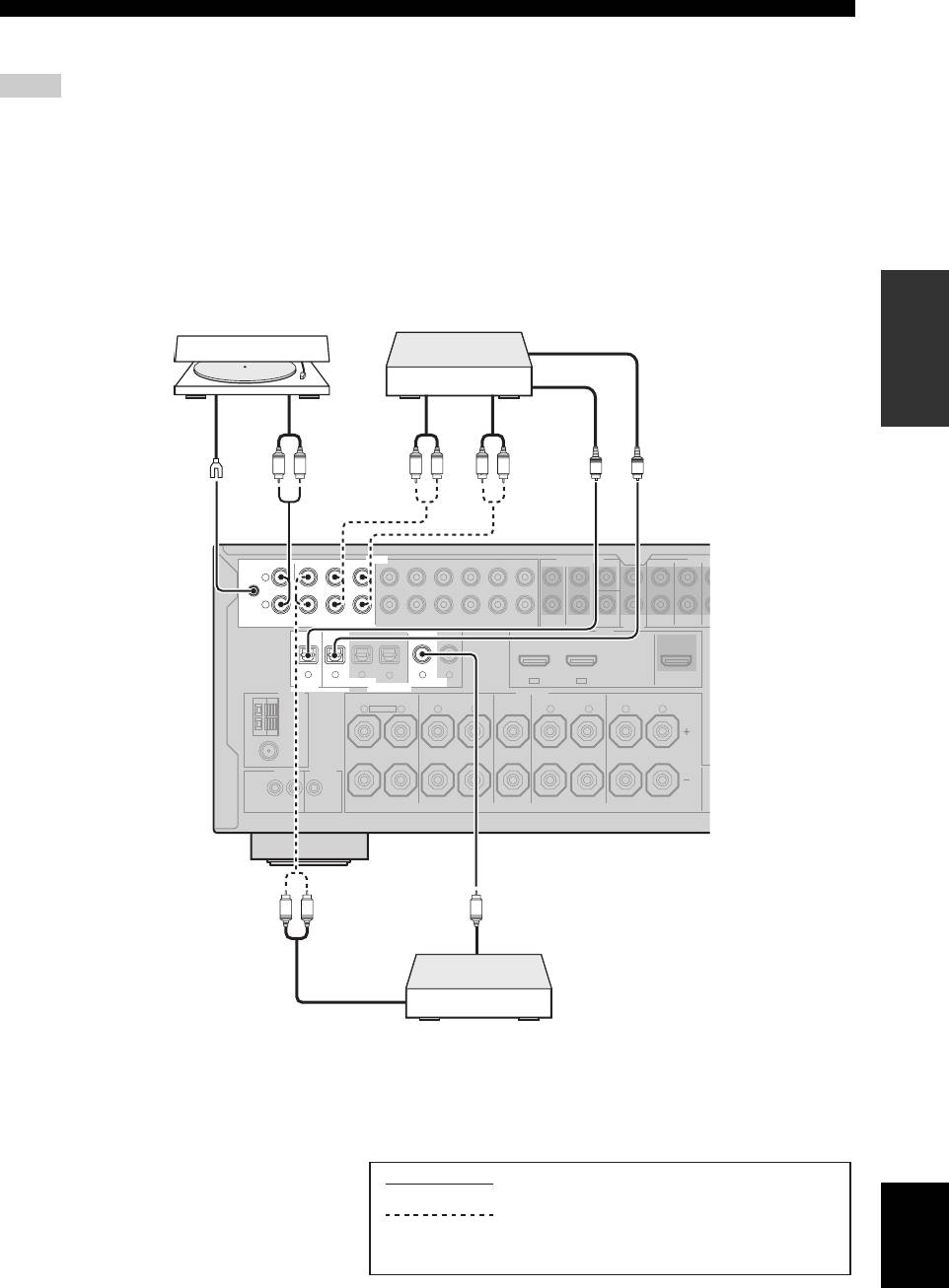
■ Connecting audio components
Notes
• To make a digital connection to a component other than the default component assigned to each the DIGITAL INPUT jack or the
DIGITAL OUTPUT jack, select the corresponding setting for “OPTICAL OUT”, “OPTICAL IN”, or “COAXIAL IN” in “I/O
ASSIGNMENT” (see page 84).
• Connect your turntable to the GND terminal of this unit to reduce noise in the signal. However, you may hear less noise without the
connection to the GND terminal for some turntables.
• The PHONO jacks are only compatible with a turntable with an MM or a high-output MC cartridge. To connect a turntable with a low-
output MC cartridge to the PHONO jacks, use an in-line boosting transformer or an MC-head amplifier.
• When you connect both the DIGITAL INPUT (OPTICAL) jack and the DIGITAL INPUT (COAXIAL) jack to an audio component,
the priority is given to the DIGITAL INPUT (COAXIAL) jack.
PREPARATION
AUDIO MULTI CH INPUT PRE OU
L
R
English
23 En
T
SUB
WOOFER
FRONTSB (8CH) ZONE 2
S
HDMI
OUT
DIGITAL
OUTPUT
DIGITAL INPUT
ANTENNA
SPEAKERS
REMOTE
TRIGGER
OUT
U
SURROUND
S
RL
RL RL
O
O
AUDIO MULTI CH INPUT PRE OU
CENTERFRONT (6CH)
L
GND
R
IN
MD/
OUT
PHONO
CD
(PLAY)
CD-R
(REC)
DVD
DTV/CBL DVR VCR
OUTININ OUT
SURROUND
MD/CD-R MD/CD-R
DVD
DVDCDDTV/CBL
321
4
65
DTV/CBLDVD
IN2IN1
OUT
OPTICAL COAXIAL
FRONT B/ZONE B/
ZONE 2/PRESENCE
SURROUND BACK/BI-AMPSURROUNDCENTERFRONT A
AM
R
EXTRA SP
L
R
L
R
L
R
L
GND
FM
75Ω
UNBAL.
+12V
IN OUT
15mA MAX.
RL
C
T
SUB
WOOFER
FRONTSB (8CH) ZONE 2
S
HDMI
OUT
DIGITAL
OUTPUT
DIGITAL INPUT
ANTENNA
SPEAKERS
REMOTE
TRIGGER
OUT
U
SURROUND
S
CD recorder, MD
Turntable
recorder or tape deck
Optical out
Audio out
Audio in
Audio out
Optical in
Ground
RL
RL RL
O
O
CENTERFRONT (6CH)
GND
IN
MD/
OUT
PHONO
CD
(PLAY)
CD-R
(REC)
DVD
DTV/CBL DVR VCR
OUTININ OUT
SURROUND
MD/CD-R MD/CD-R
DVD
DVDCDDTV/CBL
321
4
65
DTV/CBLDVD
OPTICAL COAXIAL
IN2IN1
OUT
FRONT B/ZONE B/
ZONE 2/PRESENCE
SURROUND BACK/BI-AMPSURROUNDCENTERFRONT A
AM
R
EXTRA SP
L
R
L
R
L
R
L
GND
FM
75Ω
UNBAL.
+12V
IN OUT
15mA MAX.
RL
C
Coaxial
out
Audio
out
CD player
indicates recommended connections
indicates alternative connections
(One for the audio connection)
Connections
■ Connecting an external amplifier
This unit has more than enough power for any home use. However, if you want to add more power to the speaker output
or if you want to use another amplifier, connect an external amplifier to the PRE OUT jacks. Each PRE OUT jack outputs
the same channel signals as the corresponding SPEAKERS terminals.
Notes
• When you make connections to the PRE OUT jacks, do not make connections to the SPEAKERS terminals.
• The signals output at the FRONT PRE OUT jacks are affected by the TONE CONTROL settings (see page 52).
• Adjust the volume level of the subwoofer with the control on the subwoofer (see page 52).
• Some signals may not be output at the SUBWOOFER PRE OUT jacks depending on the settings for “SPEAKER SET” (see page 76).
5
PRE OUT
SINGLE CENTER
L
R
12
SUR. BACKSURROUND
SUBWOOFERFRONT
1
2
3
4
1
FRONT PRE OUT jacks
Front channel output jacks.
2
SURROUND PRE OUT jacks
Surround channel output jacks.
3
SUR.BACK PRE OUT jacks
Surround back channel output jacks. When you only
connect one external amplifier for the surround back
channel, connect it to the SINGLE jack.
Notes
• When “BI-AMP” is set to “ON”, this unit outputs the front
channel audio signals at the SUR.BACK PRE OUT jacks.
• The audio signals output at the SUR.BACK PRE OUT jacks
differ depending on the “EXTRA SP ASSIGN” setting (see
pages 33 and 76).
4
SUBWOOFER PRE OUT jacks
Connect one or two subwoofers with a built-in amplifier.
Note
The signal output at the SUBWOOFER PRE OUT 2 jack is the
same as the one output at the SUBWOOFER PRE OUT 1 jack.
5
CENTER PRE OUT jack
Center channel output jack.
24 En
Connections
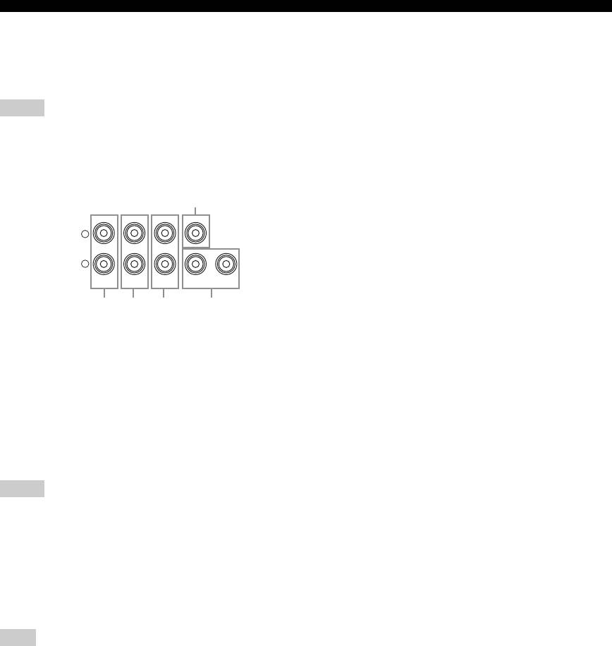
■ Connecting a multi-format player or an external decoder
This unit is equipped with 6 additional input jacks (left and right FRONT, CENTER, left and right SURROUND and
SUBWOOFER) for discrete multi-channel input from a multi-format player, external decoder, sound processor or pre-
amplifier.
If you set “INPUT CH” to “8CH” in “MULTI CH” (see page 86), you can use the input jacks assigned as “FRONT” in
“MULTI CH” (see page 86) together with the MULTI CH INPUT jacks to input 8-channel signals.
Connect the output jacks on your multi-format player or external decoder to the MULTI CH INPUT jacks. Be sure to
match the left and right outputs to the left and right input jacks for the front and surround channels.
Notes
• When you select the component connected to the MULTI CH INPUT jacks as the input source (see page 43), this unit automatically
PREPARATION
turns off the digital sound field processor, and you cannot select sound field programs.
• This unit does not redirect signals input at the MULTI CH INPUT jacks to accommodate for missing speakers. We recommend that
you connect at least a 5.1-channel speaker system before using this feature.
MULTI CH INPUT
MULTI CH INPUT
CENTERFRONT (6CH)
CENTERFRONT (6CH)
L
L
L
*1
R
R
R
SUB
Surround back out
SUB
SB (8CH)
SURROUND
WOOFER
SB (8CH)
SURROUND
WOOFER
Surround out
Surround out
L R LR
L R LRL R
Subwoofer
Subwoofer
Center out
Center out
Front out
Front out
out
out
Multi-format player/External
Multi-format player/External
decoder (5.1-channel output)
decoder (7.1-channel output)
*1
The analog audio input jacks assigned as “FRONT” in “MULTI CH” (see page 86).
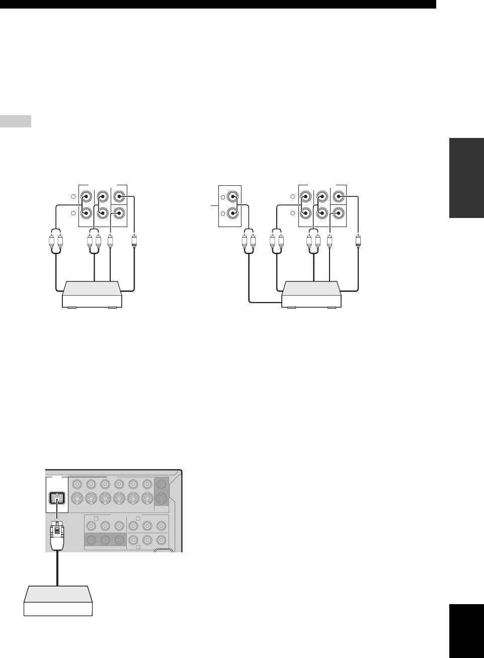
■ Connecting a Yamaha iPod universal
y
Refer to “Using iPod™” on page 60 for playback of your iPod
dock or Bluetooth adapter
and “Using Bluetooth™ components” on page 62 for playback of
This unit is equipped with the DOCK terminal on the rear
your Bluetooth components.
panel that allows you to connect a Yamaha iPod universal
dock (such as YDS-10, sold separately) or Bluetooth
adapter (such as YBA-10, sold separately). Connect a
Yamaha iPod universal dock or Bluetooth adapter to the
DOCK terminal on the rear panel of this unit using its
dedicated cable.
DOCK VIDEO
VIDEO
S VIDEO
DVD
DTV/CBL
DVR
VCR
OUTININ OUT
MONITOR
OUT
DVD
COMPONENT VIDEO
DTV/CBL
P
R
A B
P
B
Y
P
R
P
B
Y
C
DVRMONITOR OUT
English
Yamaha iPod universal dock
or Bluetooth adapter
25 En
Connections
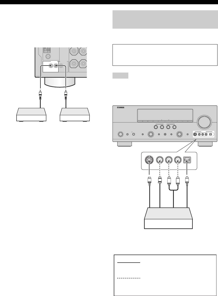
■ Using REMOTE IN/OUT jacks
When the components are the Yamaha products and have
Using the VIDEO AUX jacks on the
the capability of the transmission of the remote control
front panel
signals, connect the REMOTE IN jack and REMOTE
OUT jack to the remote control input and output jack with
Use the VIDEO AUX jacks on the front panel to connect a
the monaural analog mini cable as follows.
game console or a video camera to this unit.
GND
Caution
FM
Be sure to turn down the volume of this unit and other
75Ω
UNBAL.
REMOTE TRIGGER
components before making connections.
OUT
+12V
IN OUT
15mA MAX.
Notes
• The audio signals input at the DOCK terminal on the rear panel
take priority over the ones input at the VIDEO AUX jacks.
• To reproduce the source signals input at these jacks, select
“V-AUX” as the input source.
Remote
Remote
control out
control in
VOLUME
SEARCH MODE
EDIT
PRESET/TUNINGBANDSPEAKERS MEMORY INFO
ZONE 2
ON/OFF
CONTROLA/B/C/D/E
ZONE
SCENE
Infrared signal
Yamaha component
1234
receiver or Yamaha
(CD or DVD player,
MAIN ZONE
PROGRAM INPUT
SYSTEM OFF
PHONES
TONE CONTROL STRAIGHT PURE DIRECT
AUDIO SELECT OPTIMIZER MIC
VIDEO AUX
component
etc.)
ON/OFF
SILENT CINEMA
EFFECT
VIDEOS VIDEO
L
AUDIO OPTICAL
R
y
• If the components have the capability of the SCENE control
signals, this unit can automatically activate the corresponding
components and start the playback when you use one of the
S VIDEO
VIDEO
L
AUDIO
R
OPTICAL
SCENE buttons. Refer to the owner’s manuals for details about
the capability of the SCENE control signals of the components.
• If the component connected to the REMOTE OUT jack is not
S-Video output
S
V
L
R
O
Optical output
the Yamaha product, set “SCENE IR” in the advanced setup
Video output
Audio output
menu to “OFF” (see page 109).
Game console or
video camera
indicates recommended connections
indicates alternative connections
(One for the video connection, and
one for the audio connection)
26 En
Connections
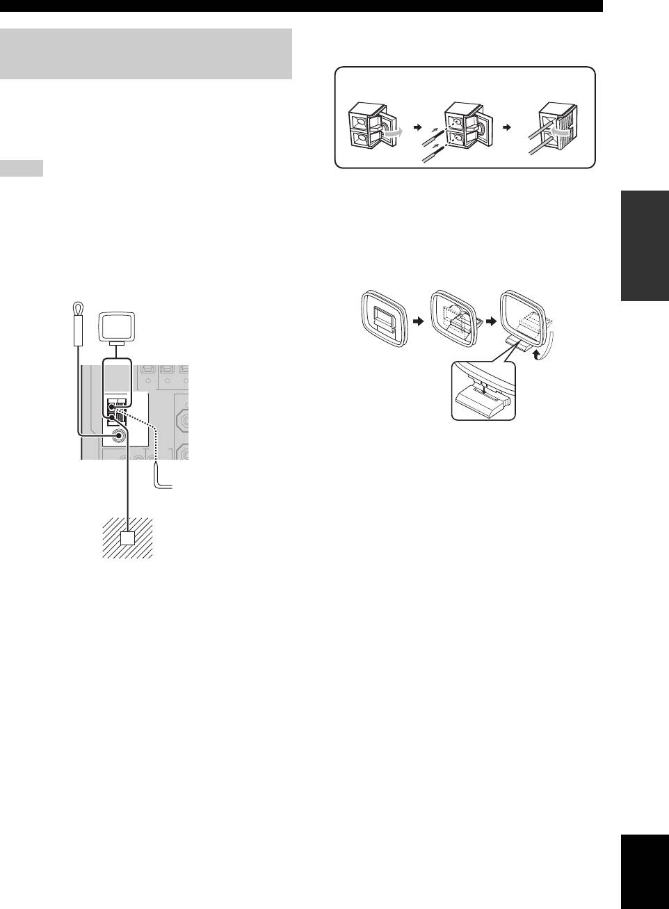
Connecting the wire of the AM loop antenna
Connecting the FM and AM
antennas
Both FM and AM indoor antennas are supplied with this
unit. Connect each antenna correctly to the designated
terminals. In general, these antennas should provide
sufficient signal strength.
Notes
• The AM loop antenna should be placed away from this unit.
y
The wire of the AM loop antenna does not have any polarity
PREPARATION
• A properly installed outdoor antenna provides clearer reception
and you can connect either end of the wire to AM or GND
than an indoor one. If you experience poor reception quality,
terminal.
install an outdoor antenna. Consult the nearest authorized
Yamaha dealer or service center about outdoor antennas.
Assembling the supplied AM loop antenna
• The AM loop antenna should always be connected, even if an
outdoor AM antenna is connected to this unit.
DV
DIGITAL
OPTIC
OUTPUT
ANTENNA
FR
AM
GND
REMOTE
TRIGGER
OUT
English
27 En
O
MD/CD-R MD/CD-R
ZO
FM
UNBAL.
R
Open the lever
Insert
Close the lever
Indoor FM
AM loop antenna
antenna
(supplied)
(supplied)
321
75
Ω
Outdoor AM antenna
Use a 5 to 10 m (16 to 33
ft) vinyl-covered wire
extended outdoors from a
window.
Ground (GND terminal)
For maximum safety and minimum interference, connect the
antenna GND terminal to a good earth ground. A good earth
ground is a metal stake driven into moist earth.
Connections
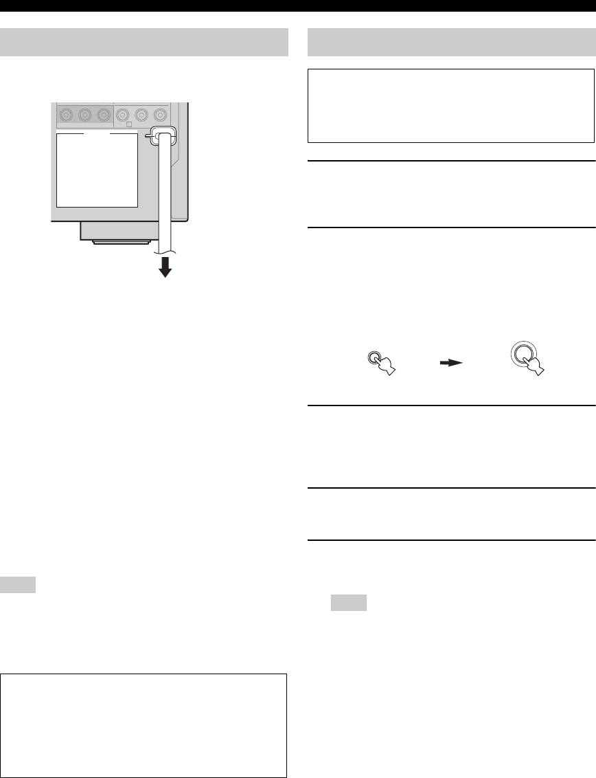
Connecting the power cable
Setting the speaker impedance
Caution
If you are to use 6 ohm speakers, set “SP IMP.” to
“6Ω MIN” as follows BEFORE using this unit. 4 ohm
C
DVRMONITOR OUT
speakers can be also used as the front speakers.
AC OUTLETS
1 Press
L
SYSTEM OFF on the front panel to
turn off this unit.
See page 29 for details.
2 Press and hold
M
TONE CONTROL and
then press
K
MAIN ZONE ON/OFF to turn
on this unit.
To the AC wall outlet
This unit turns on, and the advanced setup menu
appears in the front panel display.
MAIN ZONE
TONE CONTROL
While holding
down
ON/OFF
■ AC OUTLET(S) (SWITCHED)
Australia model ..................................................... 1 outlet
Korea model ...............................................................None
Other models .........................................................2 outlets
3 Rotate the
N
PROGRAM selector to select
Use these outlet(s) to supply power to any connected
“SP IMP.”.
components. Connect the power cable of your other
“SP IMP.” and the current speaker impedance setting
components to these outlet(s). Power to these outlet(s) is
(“8Ω MIN”) appear in the front panel display.
supplied when the main zone or Zone 2 is turned on. However,
power to these outlet(s) is cut off when the main zone and
4 Press
M
TONE CONTROL repeatedly to
Zone 2 are turned off or when
L
SYSTEM OFF
on the front
select “6Ω MIN”.
panel is pressed. For information on the maximum power or
the total power consumption of the components that can be
connected to these outlet(s), see “Specifications” on page 123.
5 Press
L
SYSTEM OFF to save the new
setting and turn off this unit.
Note
The power to AC OUTLET(S) of this unit is not cut off while this
Note
unit is charging connected iPod even when this unit is in the
The setting you made is reflected next time you turn on this
standby mode. When this unit completes charging or the iPod is
unit.
disconnected, the power is cut off automatically when this unit is
in the standby mode.
Memory back-up
The memory back-up circuit prevents the stored data
from being lost even if this unit is in the standby mode.
However, the stored data will be lost in case the power
cable is disconnected from the AC wall outlet or if the
power supply is cut off for more than one week.
28 En

Connections
Turning this unit on and off
■ Turning on this unit
Press
K
MAIN ZONE ON/OFF (or
E
POWER) to
turn on this unit.
The main zone is turned on.
y
• When you turn on this unit, there will be delay for a few
seconds before this unit can reproduce sound.
PREPARATION
• You can also turn on the main zone by pressing
S
SCENE (or
4
SCENE) buttons.
■ Set the main zone to the standby mode
Press
K
MAIN ZONE ON/OFF
(or
D
STANDBY
)
to set the main zone to the standby mode.
In the standby mode, this unit consumes a small amount of
power in order to receive infrared signals from the remote
control.
y
Press
L
SYSTEM OFF to set the main zone and Zone 2 (see
page 104) to the standby mode simultaneously.
English
29 En
Connections
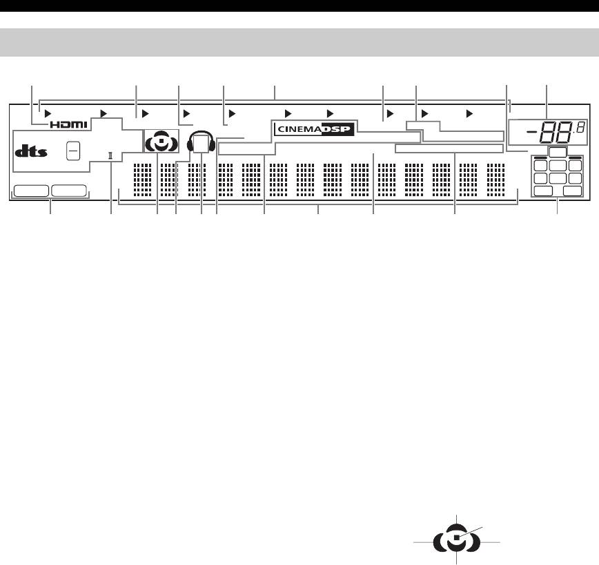
Front panel display
12345 6789
MULTI CH
VCR DVR
V-AUX
DTV/CBL
DVD CD
MD/CD-R
TUNER PHONO
q
EX
ADAPTIVE DRC
DOCK ENHANCER
YPAO
MEMORY
VOL.
MASTER AUDIO
q
DIGITAL PLUS
SP
ZONE 2
VIRTUAL
AUTO
TUNED
STEREO
MUTE
dB
HD
96
q
TRUE HD
A B
SILENT
CINEMA
SLEEP
EONCTRTPTYPSHOLDPTY
96/24
ES
24
LFE
q
PL x
MATRIX DISCRETE
LL C R
SL SB SR
PCM
DSD
SBRSBL
JHIGED FCA B0
1
HDMI indicator
9
MUTE indicator and VOLUME level indicator
Lights up when the signal of the selected input source is
• The MUTE indicator flashes while the MUTE function
input at the HDMI IN jacks (see page 18).
is on (see page 45).
• Indicates the current volume level.
2
ADAPTIVE DRC indicator
Lights up when the adaptive dynamic range control
0
Input signal indicators
feature is turned on (see page 80).
Lights up when this unit is reproducing PCM (Pulse Code
Modulation) or DSD (Direct Stream Digital) digital audio
3
DOCK indicator
signals.
• Lights up when you station your iPod in a Yamaha
iPod universal dock (such as YDS-10, sold separately)
A
Decoder indicators
connected to the DOCK terminal of this unit (see
The respective indicator lights up when any of the
page 25) and V-AUX is selected as the input source.
decoders of this unit function.
The DOCK indicator also lights up when this unit is
charging the battery of the stationed iPod in the
B
Sound field indicators
standby mode.
Light up to indicate the active sound fields (see page 48).
• Flashes while the connected Yamaha Bluetooth adapter
(such as YBA-10, sold separately) and the Bluetooth
Presence sound field
component is in the paring or the Bluetooth adapter is
Listening position
searching the Bluetooth component (see page 62).
Surround left
Surround right
• Light up while the Yamaha Bluetooth adapter is
sound field
sound field
connected to the Bluetooth component (see page 62).
Surround back sound field
4
ENHANCER indicator
C
Headphone indicator
Lights up when the Compressed Music Enhancer mode is
Lights up when headphones are connected (see page 45).
selected (see page 50).
D
5
SP A B indicators
Input source indicators
Light up according to the set of front speakers activated
The corresponding cursor lights up to show the currently
(see page 43).
selected input source.
SP A: The FRONT A speakers are activated.
6
YPAO indicator
SP B: The FRONT B speakers are activated.
Lights up when you run “AUTO SETUP” and when the
SP A B: The FRONT A and FRONT B speakers are
speaker settings set in “AUTO SETUP” are used without
activated.
any modifications (see page 32).
E
ZONE2 indicator
7
Tuner indicators
Lights up when Zone 2 is turned on (see page 104).
Lights up when this unit is in the FM or AM tuning mode
F
DSP indicators
(see pages 53 to 56).
The respective indicator lights up when any of the sound
8
96/24 indicator
field programs are selected (see page 48).
Lights up when a DTS 96/24 signal is input to this unit.
CINEMA DSP indicator
Lights up when you select a CINEMA DSP sound
field program (see page 48).
30 En
Connections
VIRTUAL indicator
Lights up when the Virtual CINEMA DSP mode is
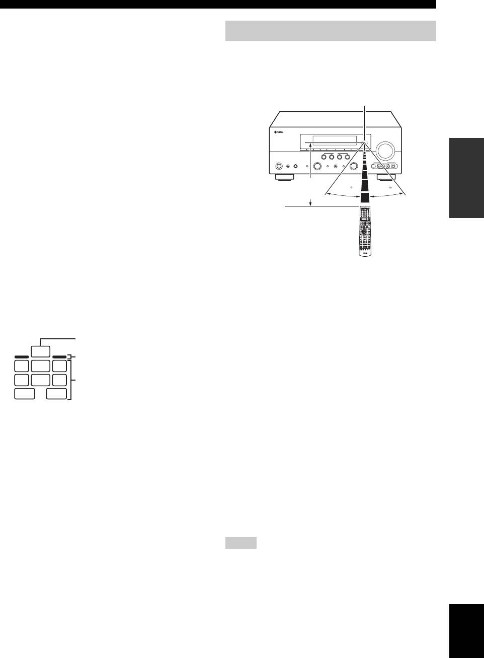
Using the remote control
active (see page 51).
The remote control transmits a directional infrared ray.
SILENT CINEMA indicator
Be sure to aim the remote control directly at the remote
Lights up when headphones are connected and a
control sensor on this unit during operation.
sound field program is selected (see page 51).
Remote control sensor
G
Multi-information display
Shows the name of the current sound field program and
other information when adjusting or changing settings.
H
SLEEP indicator
PREPARATION
Lights up while the sleep timer is on (see page 47).
I
Radio Data System indicators
(Europe and Russia models only)
Approximately 6 m (20 ft)
30 30
PTY HOLD
Lights up while this unit is in the PTY SEEK mode
(see page 57).
PS, PTY, RT and CT
Light up according to the available Radio Data System
information (see page 59).
Infrared window (
1
)
EON
Outputs infrared control signals. Aim this window at the
component you want to operate.
Lights up when the EON data service is available (see
page 58).
Transmit indicator (
2
)
J
Input channel and speaker indicators
Flashes while the remote control is sending infrared
signals.
LFE indicator
Display window (
6
)
LFE
Presence speaker indicators
Shows the name of the selected input source that you can
LL C R
control.
Input channel indicators
SL SB SR
Operation mode selector (
F
)
SBRSBL
The function of some buttons depends on the operation
Input channel indicators
mode selector position.
• Indicate the channel components of the current
AMP
digital input signal.
Operates the amplifier function of this unit.
• Light up or flash according to the settings of the
speakers when this unit is in the automatic setup
SOURCE
procedure (see page 32) or in the “BASIC MENU”
Operates the component selected with an input
in “MANUAL SETUP” (see page 78).
selector button (see page 92).
Presence speaker indicators
TV
Light up or flash according to the setting of “EXTRA
Operates the TV assigned to either DTV/CBL or
SP ASSIGN” when this unit is in the automatic setup
PHONO (see page 91).
procedure (see page 32) or in the “BASIC MENU” in
“MANUAL SETUP” (see page 76).
Notes
y
• Do not spill water or other liquids on the remote control.
You can make settings for the presence and surround back
• Do not drop the remote control.
speakers automatically by running “AUTO SETUP” (see
• Do not leave or store the remote control in the following types
page 32) or manually by adjusting settings for “SUR.B L/R
of conditions:
SP” (see page 77) in “SPEAKER SET”.
– places of high humidity, such as near a bath
– places of high temperatures, such as near a heater or stove
English
– places of extremely low temperatures
– dusty places
• To set the remote control codes for other components, see
page 93.
31 En
Оглавление
- Caution: Read this before operating your unit.
- Contents
- Features
- Notice
- Getting started
- Quick start guide
- Connections
- Optimizing the speaker setting for your listening room (YPAO)
- Selecting the SCENE templates
- Playback
- Sound field programs
- Using audio features
- FM/AM tuning
- Radio Data System tuning (Europe and Russia models only)
- Using iPod™
- Using Bluetooth™ components
- Recording
- Advanced sound configurations
- Customizing this unit (MANUAL SETUP)
- Remote control features
- Using multi-zone configuration
- Advanced setup
- Troubleshooting
- Resetting the system
- Glossary
- Sound field program information
- Specifications
- Index
- Предупреждение: Внимательно изучите это перед использованием аппарата.
- Содержание
- Описание
- Уведомление
- Начало работы
- Краткое руководство пользователя
- Подключения
- Оптимизация настройки колонок для комнаты для прослушивания (YPAO)
- Выборе шаблонов SCENE
- Воспроизведение
- Программы звукового поля
- Использование аудиофункций
- Настройка радиопрограмм диапазона ЧМ/AM
- Функция настройки Системы Радиоданных (Только модели для Европы и России)
- Использование iPod™
- Использование компонентов Bluetooth™
- Запись
- Дополнительные конфигурации звучания
- Настройка данного аппарата (MANUAL SETUP)
- Функции пульта ДУ
- Использование многозонной конфигурации
- Дополнительные настройки
- Возможные неисправности и способы по их устранению
- Перезагрузка системы
- Справочник
- Информация программы звукового поля
- Технические характеристики
- Предметный указател


