Yamaha RX-V663 Black: Quick start guide
Quick start guide: Yamaha RX-V663 Black
Quick start guide
Quick start guide
INTRODUCTION
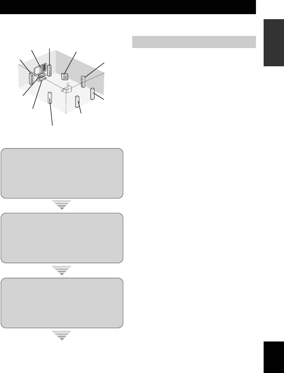
The following steps describe the easiest way to enjoy DVD movie playback in your home theater. See pages 11 to 15 for
details of the speaker placement.
Front right
speaker
Preparation: Check the items
Video monitor
Subwoofer
Front left
Surround right
Prepare the following items.
speaker
speaker
❏ Speakers
❏ Front speakers ...................................x 2
❏ Center speaker ..................................x 1
❏ Surround speakers ............................ x 4
Select magnetically shielded speakers. The
Center
speaker
minimum required speakers are two front speakers.
Surround back
right speaker
The priority of the requirement of other speakers is
DVD player
as follows:
Surround back left
speaker
1. Two surround speakers
Surround left
2. Center speaker
speaker
3. One (or two) surround back speaker(s)
❏ Active subwoofer ................................... x 1
Select an active subwoofer equipped with an RCA
input jack.
Step 1: Set up your speakers
❏ Speaker cables ....................................... x 7
❏ Subwoofer cable .................................... x 1
Select a monaural RCA cable.
☞
P. 6
❏ DVD player .............................................. x 1
Select DVD player equipped with coaxial digital
audio output jack and composite video output
jack.
❏ Video monitor ......................................... x 1
Step 2: Connect your DVD player
Select a TV monitor, video monitor or projector
and other components
equipped with a composite video input jack.
❏ Video cable ............................................. x 2
☞
P. 7
Select an RCA composite video cable.
❏ Digital coaxial audio cable .................... x 1
y
You can also connect two subwoofers to this unit. In this
case, prepare two active subwoofers and subwoofer cables.
Step 3: Press SCENE 1 button
☞
P. 8
English
Enjoy DVD playback!
5 En
Quick start guide
Be sure to connect the left channel (L), right channel
Step 1: Set up your speakers
(R), “+” (red) and “–” (black) properly.
Place your speakers in the room and connect them to this
Front speakers and center speaker
unit.
PRE OUT SUBWOOFER 1 jack
AUDIO MULTI CH INPUT PRE OUT DOCK VIDEO
SINGLE CENTERCENTERFRONT (8CH)
VIDEO
L
GND
R
PHONO
CD
(PLAY)
IN
CD-R
MD/
(REC)
OUT
DVD
DTV/CBL DVR VCR
OUTININ OUT
SURROUND
WOOFER
SUB
1 2
OUT
SUR. BACKSURROUND
DVDSUBWOOFERFRONTSB (8CH) ZONE 2
S VIDEO
DTV/CBL
DVR
VCR
OUTININ OUT
MONITOR
HDMI
P
R
A B
P
B
DVD
COMPONENT VIDEO
OUT
Y
R
P
DTV/CBL
P
B
Y
MD/CD-R MD/CD-R
DVD
321
4
DVDCDDTV/CBL
DIGITAL
OPTICAL COAXIAL
65
DTV/CBLDVD
OUT
ANTENNA
OUTPUT
DIGITAL INPUT
IN2IN1
FRONT B/ZONE B/
SPEAKERS
ZONE 2/PRESENCE
CENTERFRONT A
SURROUND BACK/BI-AMPSURROUND
C
DVRMONITOR OUT
AM
R
EXTRA SP
L
R
L
R
L
R
L
AC OUTLETS
GND
FM
UNBAL.
75Ω
REMOTE
TRIGGER
OUT
IN OUT
15mA MAX.
+12V
SINGLE
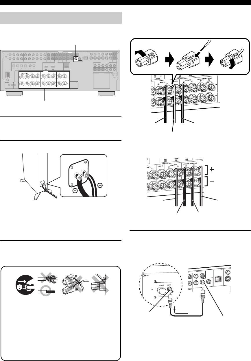
Speaker terminals
1 Place your speakers and subwoofer in the
room.
2 Connect speaker cables to each speaker.
Surround and surround back speakers
Be sure to connect the “+” (red) and “–” (black) properly.
Cables are colored or shaped differently, perhaps with a
stripe, groove or ridge. Connect the striped (grooved, etc.)
cable to the “+” (red) terminals of this unit and your speaker.
Connect the plain cable to the “–” (black) terminals.
4 Connect the subwoofer cable to the
SUBWOOFER PRE OUT 1 jack of this unit
3 Connect each speaker cable to the
and the input jack of the subwoofer.
corresponding speaker terminal of this unit.
12 3 4
y
You can also connect another subwoofer to the SUBWOOFER
PRE OUT 2 jack.
6 En
Loosen Insert Tighten
To the front right
To the center speaker
speaker
To the front left
speaker
To the surround
To the surround
right speaker
back left speaker
To the surround
To the surround
left speaker
back right speaker
4
DOCK
PRE OUT
DVD
SUR. BACK
SUBWOOFER
1
Make sure that this unit and the subwoofer are
unplugged from the AC wall outlets.
2
Twist the exposed wires of the speaker cables
together to prevent short circuits.
3
Do not let the bare speaker wires touch each
other.
4
Do not let the bare speaker wires touch any
metal part of this unit.
R
SINGLE
CENTER
S VI
ROUND
D
VID
E
AV receiverSubwoofer
12
Input jack
Subwoofer cable
SUBWOOFER PRE
OUT 1 jack
Quick start guide
y
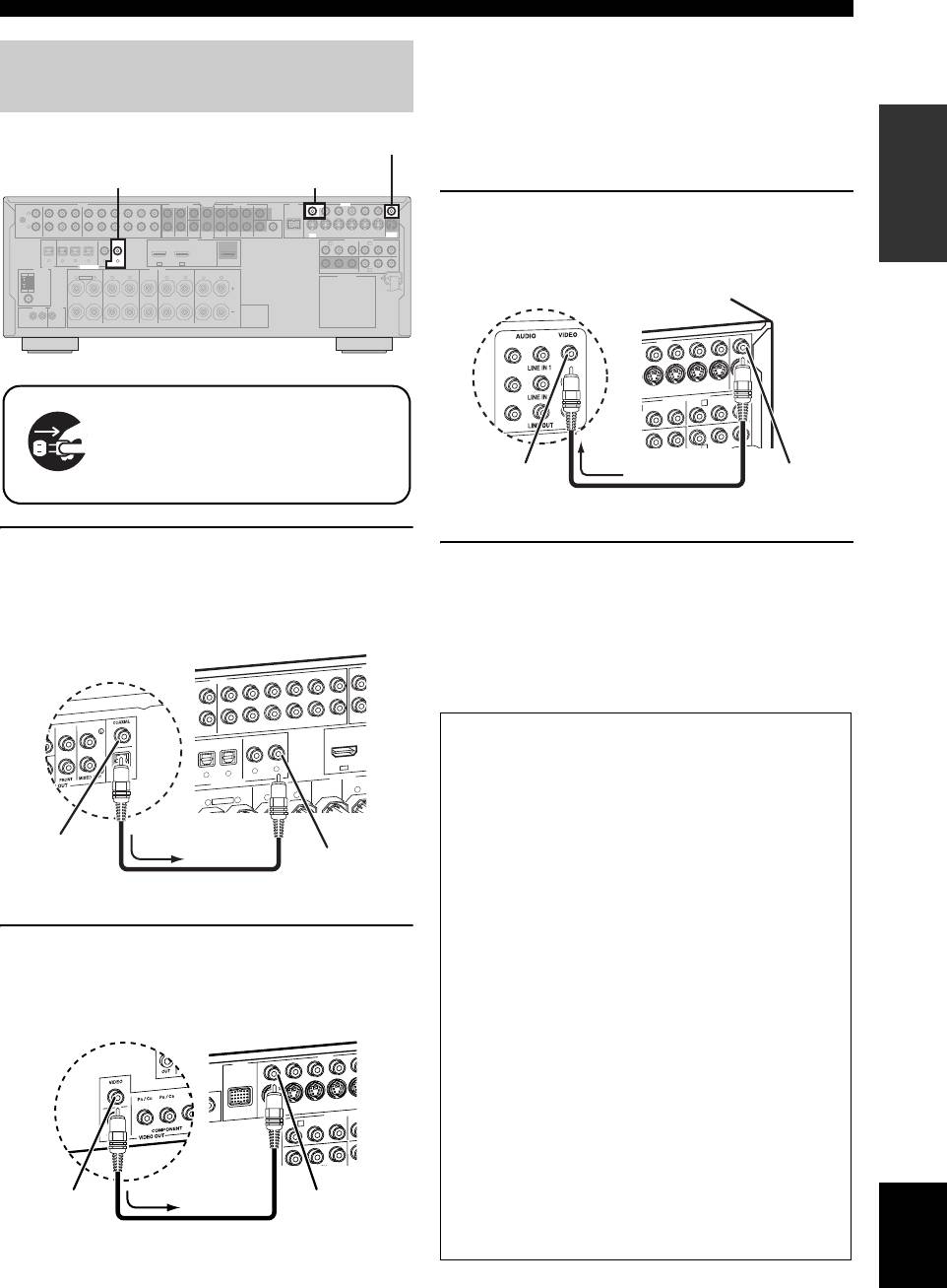
Step 2: Connect your DVD player
• When you connect a component that has only a SCART
jack, use an appropriate converter. The connection
and other components
between a converter and this unit depends on signals that
INTRODUCTION
are available on the converter. For details, refer to the
VIDEO MONITOR OUT jack
instructions of your converter.
• This unit cannot transmit RGB signals.
DVD DIGITAL INPUT COAXIAL jack DVD VIDEO jack
AUDIO MULTI CH INPUT PRE OUT DOCK VIDEO
SINGLE CENTERCENTERFRONT (8CH)
VIDEO
L
3 Connect the video cable to the VIDEO
GND
R
PHONO
CD
(PLAY)
IN
CD-R
MD/
(REC)
OUT
DVD
DTV/CBL DVR VCR
OUTININ OUT
SURROUND
WOOFER
SUB
SUR. BACKSURROUND
12
DVDSUBWOOFERFRONTSB (8CH) ZONE 2
S VIDEO
OUTININ OUT
HDMI
OUT
DTV/CBL
DVR
VCR
MONITOR
OUT
MONITOR OUT jack of this unit and the video
P
R
A B
P
B
DVD
Y
COMPONENT VIDEO
P
R
DTV/CBL
P
B
Y
MD/CD-R MD/CD-R
DVD
DIGITAL
OPTICAL COAXIAL
321
4
DVDCDDTV/CBL
65
DTV/CBLDVD
IN2IN1
OUT
input jack of your video monitor.
ANTENNA
OUTPUT
DIGITAL INPUT
FRONT B/ZONE B/
SPEAKERS
ZONE 2/PRESENCE
CENTERFRONT A
SURROUND BACK/BI-AMPSURROUND
C
DVRMONITOR OUT
AM
R
EXTRA SP
L
R
L
R
L
R
L
AC OUTLETS
GND
FM
UNBAL.
75Ω
REMOTE
TRIGGER
OUT
IN OUT
15mA MAX.
+12V
SINGLE
Make sure that this unit and the DVD
player are unplugged from the AC
wall outlets.
1 Connect the digital coaxial audio cable to the
4 Connect the power plug of this unit and other
digital coaxial audio output jack of your DVD
components into the AC wall outlet.
player and the DVD DIGITAL INPUT COAXIAL
jack of this unit.
y
This unit is equipped with AC OUTLET(S) for the power
supply of the other components (except Korea model). See
AUDIO
AUDIO
page 28 for details.
DVD
2 Connect the video cable to the composite
video output jack of your DVD player and
DVD VIDEO jack of this unit.
English
7 En
M
SB (8C
SPEAKERS
DIGITAL INPUT
H
FRONT (8C
H
DVD
CD
DVD
DVD
DTV/CBL
COAXIAL
OPTICAL
S
U
D/
DVD
FRONT A
CENTER
FRONT B/ZONE B/
ZONE 2/PRESENCE
D
AV receiver
DVD player
U
T
IN
T
DVR
VCR
O
U
IN O
OUT
-R
(REC)
DTV/CBL
4
5
6
IN1
3
R
L
R
L
R
EXTRA SP
Digital coaxial
audio output
DVD DIGITAL
jack
INPUT COAXIAL
Digital coaxial audio
jack
cable
VIDEO
DOCK
COMPONENT
V
V
I
DEO
S VIDEO
DVR
DVD
DTV/CBL
DVD
OUT
VIDEO
DVR
COMPONENT VIDEO
DTV/CBL
DVD
■ For further connections
• Using the other kind of speaker combinations
☞ P. 11
• Connecting a video monitor via various ways of the
connection ☞ P. 20
• Connecting a DVD player via various ways of the
connection ☞ P. 21
• Connecting a DVD recorder or a digital video
recorder ☞ P. 22
• Connecting a set-top box ☞ P. 22
• Connecting a CD player, an MD recorder or a
turntable ☞ P. 23
DVD player
AV receiver
• Connecting an external amplifier ☞ P. 24
• Connecting a DVD player via analog multi-channel
audio connection ☞ P. 25
IN
OUT
• Connecting a Yamaha iPod universal dock or
R
A
P
B
Y
P
R
P
Bluetooth adapter ☞ P. 25
• Using the REMOTE IN/OUT jacks ☞ P. 26
• Using the VIDEO AUX jacks on the front panel
Composite
DVD VIDEO jack
video output
☞ P. 26
jack
Video cable
• Connecting a FM/AM antenna ☞ P. 27
DVR
IN
VCR
OUT
MONITOR
IN
OUT
OUT
P
R
P
B
Y
P
B
Y
B
C
AV receiver
Video monitor
Video input jack
VIDEO
MONITOR OUT
Video cable
jack
Quick start guide
■ About SCENE function
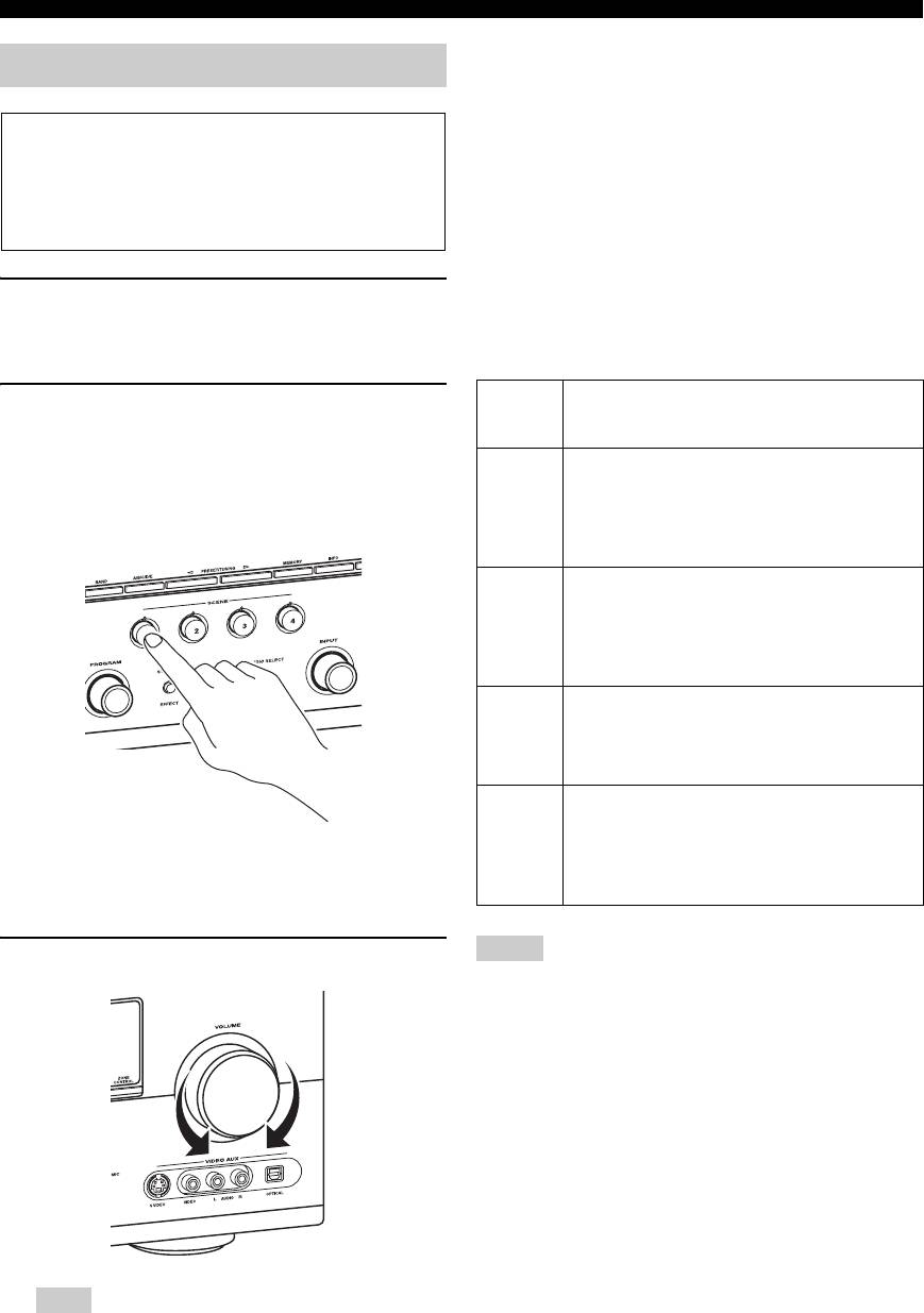
Step 3: Press SCENE 1 button
Just by pressing one SCENE button, you can turn on this
unit and recall your favorite input source and sound field
program according to the SCENE template that has been
Check the type of the connected speakers.
assigned to the SCENE button. The SCENE templates are
If the speakers are 6 ohm speakers, set “SP IMP.” to
built combinations of input sources and sound field
“6Ω MIN” before using this unit (see page 28). 4 ohm
programs.
speakers can be also used as the front speakers (see
page 106).
y
If you connect a Yamaha product that has capability of the
SCENE control signals, this unit can automatically activate the
component and start playback. Refer to the instruction manual of
1 Turn on the video monitor and then set the
the DVD player for further information.
input source selector of the video monitor to
this unit.
■ The default assigned SCENE templates
Default
The name of the SCENE template
2 Press
S
SCENE1 button.
SCENE
and its description
This unit is turned on. “DVD Movie Viewing”
button
appears in the front panel display, and this unit
SCENE
DVD Movie Viewing
automatically optimize own status for the DVD
1
– input source: DVD
playback.
– sound field program: Sci-Fi
For when you want to enjoy a movie from the
connected DVD player.
SCENE
Music Disc Listening
2
– input source: DVD
– sound field program: 2ch Stereo
For when you want to listen to a music disc from
the connected DVD player.
SCENE
TV Viewing
*1
3
– input source: DTV/CBL
– sound field program: Straight
For when you want to watch a TV program.
SCENE
Radio Listening
*2, *3, *4
4
– input source: TUNER
– sound field program: 7ch Enhancer
y
For when you want to listen to a music program
The indicator on the selected SCENE button lights up while
from the FM radio station.
this unit is in the SCENE mode.
Notes
3 Rotate
J
VOLUME to adjust the volume.
*1
You must connect a cable TV or a satellite tuner to this unit in
advance. See page 22 for details.
*2
You need to connect the supplied FM and AM antennas to this
unit in advance. See page 27 for details.
*3
You must tune into the desired radio station in advance. See
pages 53 to 56 for tuning information.
*4
To achieve the best possible reception, orient the connected
AM loop antenna, or adjust the position of the end of the
indoor FM antenna.
y
You can change the assigned SCENE template for the SCENE
buttons. See page 37 for details.
Note
When you change the input source or sound field program,
the SCENE mode is deactivated.
8 En
Quick start guide
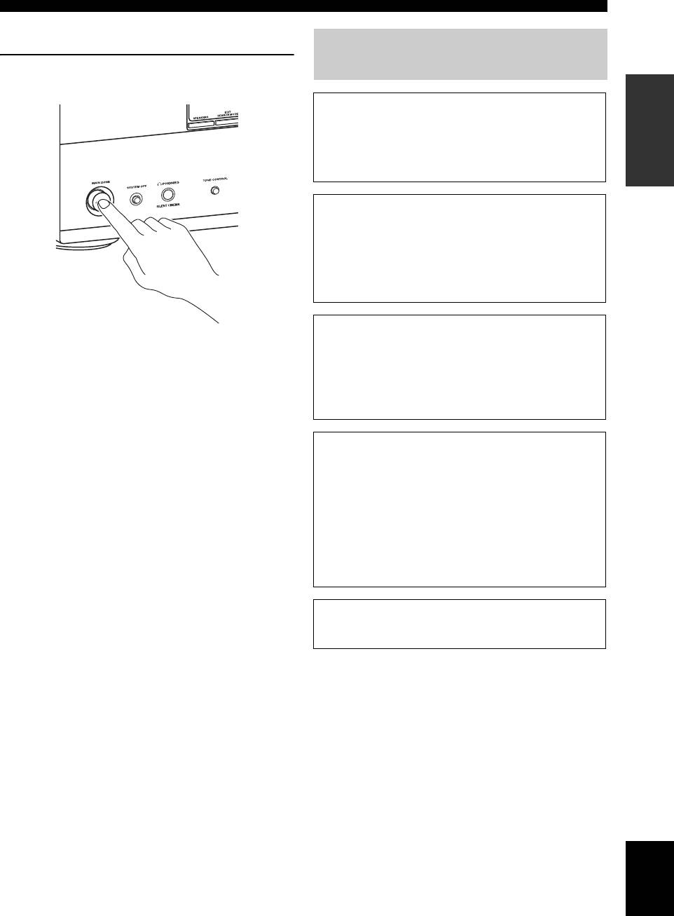
■ After using this unit...
What do you want to do with this
Press
K
MAIN ZONE ON/OFF to set this unit to
unit?
INTRODUCTION
the standby mode.
■ Customizing the SCENE templates
• Using various SCENE templates ☞ P. 37
• Creating your original SCENE templates
☞ P. 40
■ Using various input sources
• Basic controls of this unit ☞ P. 42
• Enjoying FM/AM radio programs ☞ P. 53
• Using your iPod with this unit ☞ P. 60
• Using the Bluetooth components ☞ P. 62
■ Using various sound features
This unit is set to the standby mode and consumes a small
amount of power in order to receive infrared signals from
• Using various sound field programs ☞ P. 48
the remote control. To turn on this unit from the standby
• Using the pure direct mode for high
mode, press the desired
S
SCENE buttons
fidelity sound ☞ P. 52
(or
4
SCENE) or
K
MAIN ZONE ON/OFF
• Customizing the sound field programs ☞ P. 64
(or
E
POWER). See page 29 for details.
■ Adjusting the parameters of this unit
• Automatically optimizing the speaker parameters
for your listening room
(AUTO SETUP) ☞ P. 32
• Manually adjusting various parameters of this unit
☞ P. 71
• Setting the remote control ☞ P. 91
• Adjusting the advanced parameters ☞ P. 106
■ Additional feature
• Automatically turning off this unit ☞ P. 47
English
9 En
Оглавление
- Caution: Read this before operating your unit.
- Contents
- Features
- Notice
- Getting started
- Quick start guide
- Connections
- Optimizing the speaker setting for your listening room (YPAO)
- Selecting the SCENE templates
- Playback
- Sound field programs
- Using audio features
- FM/AM tuning
- Radio Data System tuning (Europe and Russia models only)
- Using iPod™
- Using Bluetooth™ components
- Recording
- Advanced sound configurations
- Customizing this unit (MANUAL SETUP)
- Remote control features
- Using multi-zone configuration
- Advanced setup
- Troubleshooting
- Resetting the system
- Glossary
- Sound field program information
- Specifications
- Index
- Предупреждение: Внимательно изучите это перед использованием аппарата.
- Содержание
- Описание
- Уведомление
- Начало работы
- Краткое руководство пользователя
- Подключения
- Оптимизация настройки колонок для комнаты для прослушивания (YPAO)
- Выборе шаблонов SCENE
- Воспроизведение
- Программы звукового поля
- Использование аудиофункций
- Настройка радиопрограмм диапазона ЧМ/AM
- Функция настройки Системы Радиоданных (Только модели для Европы и России)
- Использование iPod™
- Использование компонентов Bluetooth™
- Запись
- Дополнительные конфигурации звучания
- Настройка данного аппарата (MANUAL SETUP)
- Функции пульта ДУ
- Использование многозонной конфигурации
- Дополнительные настройки
- Возможные неисправности и способы по их устранению
- Перезагрузка системы
- Справочник
- Информация программы звукового поля
- Технические характеристики
- Предметный указател


