Pioneer FH-460UI: Installation
Installation: Pioneer FH-460UI
Table of contents
- About this unit If you experience problems
- Head unit Display indication Basic operations Set up menu
- Radio
- CD/CD-R/CD-RW and USB storage devices
- iPod
- Using connected device applications Audio adjustments
- System menu
- Initial menu System menu Using an AUX source
- Connections This unit Power cord
- Installation
- Troubleshooting Error messages
- Handling guidelines
- Compressed audio compatibility (disc, USB)
- iPod compatibility Russian character chart Sequence of audio files Copyright and trademark
- Specifications
Black plate (11,1)
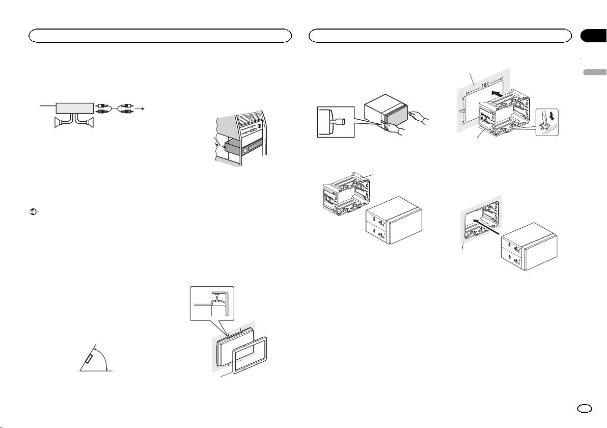
Power amp (sold separately)
! When installing, to ensure proper heat dis-
persal when using this unit, make sure you
Perform these connections when using the op-
leave ample space behind the rear panel and
tional amplifier.
wrap any loose cables so they are not block-
3
ing the vents.
1
2
4
55
1 System remote control
Connect to Blue/white cable.
2 Power amp (sold separately)
3 Connect with RCA cables (sold separately)
4 To Rear output or subwoofer output
5 Rear speaker or subwoofer
Installation
Important
! Check all connections and systems before
final installation.
! Do not use unauthorized parts as this may
cause malfunctions.
! Consult your dealer if installation requires
drilling of holes or other modifications to the
vehicle.
! Do not install this unit where:
— it may interfere with operation of the vehicle.
— it may cause injury to a passenger as a result
of a sudden stop.
! The semiconductor laser will be damaged if
it overheats. Install this unit away from hot
places such as near the heater outlet.
! Optimum performance is obtained when the
unit is installed at an angle of less than 60°.
60°
5cmcm
Leave ample
5 cm
space
5 cm
! Use commercially available parts when in-
stalling.
How to install
This unit can be installed properly using either
of the methods in the below list.
! Installation with the holder
! Installation using the screw holes on the side
of the unit
Before installing this unit
1 Remove the trim ring.
1
2 Insert the supplied extraction keys into
1
both sides of the unit until they click into
place.
3 Pull the unit out of the holder.
Remove the holder.
1
1 Holder
(factory-supplied part)
Installation with the holder
1 Install the holder into the dashboard.
After inserting the holder into the dashboard, se-
lect and bend the tabs appropriate to the thick-
ness of the dashboard material. (Install this unit
as firmly as possible using the top and bottom
tabs. To secure this unit, bend the tabs 90 de-
grees.)
1 Trim ring
2
Section
Installation
Installation
03
English
1 Dashboard
2 Holder
(factory-supplied part)
2 Install this unit.
1
1 Dashboard
En
11
<QRD3247-A>11
