Pioneer VSX-1021: Bi-amping your speakers Installing your speaker system
Bi-amping your speakers Installing your speaker system: Pioneer VSX-1021
Table of contents
- IMPORTANT VENTILATION CAUTION Operating Environment
- Contents Flow of settings on the receiver
- Before you start
- Deleting the AVNavigator Remote control
- Connecting your equipment
- Placing the speakers Connecting the speakers
- Bi-amping your speakers Installing your speaker system
- Selecting the Speaker system About the audio connection About the video converter
- About HDMI
- Connecting your TV and playback components
- Connecting an HDD/DVD recorder, BD recorder and other video sources
- Connecting a satellite/cable receiver or other set-top box Connecting other audio components
- MULTI-ZONE setup Sub Zone Input functions available Sub Zone Input functions available Connecting AM/FM antennas
- Connecting to the network through LAN interface Connecting to a wireless LAN Plugging in the receiver
- Basic Setup
- Operation Mode Setup
- Operable functions/
- Basic playback
- Playing a USB device
- Playback with HOME MEDIA GALLERY inputs Bluetooth ADAPTER for Wireless Enjoyment of Music
En
8
02
Connecting your equipment
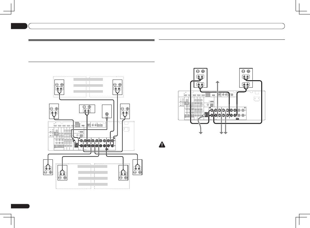
Bi-amping your speakers
Bi-amping is when you connect the high frequency driver and low frequency driver of your speakers
to different amplifiers for better crossover performance. Your speakers must be bi-ampable to do
this (having separate terminals for high and low) and the sound improvement will depend on the
kind of speakers you’re using.
HDMI
VIDEO
CONTROL
IR
COMPONENT VIDEO
VIDEO IN
TV/SAT
IN
ZONE 2
DVR/BDR CD-R/TAPE ZONE 2
DVR/
BDR
OUT
OUT
DVD IN
IN
IN
IN
IN
CD
L
R
L
R
IN
L
R
OUT
OUT
VIDEO
IN
DVD IN
BD IN
DVR/BDR IN
FM UNBAL
75
FRONT
CENTER
SURROUND
SURROUND BACK / ZONE 2
R
L
R
L
R
L
R
L
(Single)
AM LOOP
(
CD
)
(
DVD
)
TV/SAT VIDEO
DVD
Y
P
B
P
R
(
DVR/BDR
)
(
TV/SAT
)
COAXIAL
(10/100)
LAN
AUDIO
PRE OUT
SPEAKERS
ANTENNA
OPTICAL
ASSIGN
ABLE
ASSIGNABLE
ASSIGNABLE
OUT
MONITOR
OUT
MONITOR
OUT
SUBWOOFER
IN
1
(DVD)
IN
1
(DVR/
BDR)
IN
2
ASSIGNABLE
1
IN
1
IN
2
IN
1
IN
2
SEE INSTRUCTION MANUAL
SELECTABLE
SELECTABLE
VOIR LE MODE D’EMPLOI
CAUTION:
SPEAKER IMPEDANCE
6 -16 .
ATTENTION:
ENCEINTE D’IMPEDANCE DE
6 -16 .
FRONT HEIGHT / WIDE /
B
A
OUT
IN
OUT
IN
DC OUTPUT
for WIRELESS LAN
(OUTPUT 5 V
0.1 A MAX)
ADAPTER PORT
(OUTPUT 5 V 0.6 A MAX)
AC IN
High
Low
High
Low
Front right
Front left
Bi-amp compatible
speaker
Subwoofer
Bi-amp compatible
speaker
Center
Surround right
Surround left
CAUTION
!
Most speakers with both
High
and
Low
terminals have two metal plates that connect the
High
to the
Low
terminals. These must be removed when you are bi-amping the speakers or you could
severely damage the amplifier. See your speaker manual for more information.
!
If your speakers have a removable crossover network, make sure you do not remove it for bi-amping.
Doing so may damage your speakers.
Installing your speaker system
At the very least, front left and right speakers only are necessary. Note that your main surround
speakers should always be connected as a pair, but you can connect just one surround back
speaker if you like (it must be connected to the left surround back terminal).
Standard surround connection
HDMI
VIDEO
CONTROL
IR
COMPONENT VIDEO
VIDEO IN
TV/SAT
IN
ZONE 2
DVR/BDR CD-R/TAPE ZONE 2
DVR/
BDR
OUT
OUT
DVD IN
IN
IN
IN
IN
CD
L
R
L
R
IN
L
R
OUT
OUT
VIDEO
IN
DVD IN
BD IN
DVR/BDR IN
FM UNBAL
75
FRONT
CENTER
SURROUND
SURROUND BACK / ZONE 2
R
L
R
L
R
L
R
L
(Single)
AM LOOP
(
CD
)
(
DVD
)
TV/SAT VIDEO
DVD
Y
P
B
P
R
(
DVR/BDR
)
(
TV/SAT
)
COAXIAL
(10/100)
LAN
AUDIO
PRE OUT
SPEAKERS
ANTENNA
OPTICAL
ASSIGN
ABLE
ASSIGNABLE
ASSIGNABLE
OUT
MONITOR
OUT
MONITOR
OUT
SUBWOOFER
IN
1
(DVD)
IN
1
(DVR/
BDR)
IN
2
ASSIGNABLE
1
IN
1
IN
2
IN
1
IN
2
SEE INSTRUCTION MANUAL
SELECTABLE
SELECTABLE
VOIR LE MODE D’EMPLOI
CAUTION:
SPEAKER IMPEDANCE
6 -16 .
ATTENTION:
ENCEINTE D’IMPEDANCE DE
6 -16 .
FRONT HEIGHT / WIDE /
B
A
OUT
IN
OUT
IN
DC OUTPUT
for WIRELESS LAN
(OUTPUT 5 V
0.1 A MAX)
ADAPTER PORT
(OUTPUT 5 V 0.6 A MAX)
AC IN
LINE LEVEL
INPUT
The front height terminals can also be used
for the front wide and Speaker B speakers.
Front height setting
Front height right
Front height left
Front wide setting
Front wide right
Front wide left
Speaker B setting
Speaker B - right
Speaker B - left
Front right
Center
Subwoofer
Front left
The surround back terminals can also be
used for ZONE 2.
Surround left
5.1 ch surround setting
Not connected
Not connected
6.1 ch surround setting
Not connected
Surround back
7.1 ch surround setting
Surround back right
Surround back left
ZONE 2 setting
ZONE 2 - Right
ZONE 2 - Left
Surround right
