Pioneer DEH-P8100BT: Contents Connecting the units
Contents Connecting the units: Pioneer DEH-P8100BT
Table of contents
- Contents Connecting the units
- Connecting the units
- Connecting the power cord
- Connecting the units
- When connecting to separately sold power amp
- Connecting the units
- Installation DIN Front/Rear-mount Removing or attaching the trim ring DIN Front-mount
- Removing the Unit Installing the microphone When installing the microphone on the sun visor DIN Rear mount
- When installing the microphone Installing the steering remote on the steering column control Adjusting the microphone angle
- Installing the unit on a left-hand drive car
Contents Connecting the units
Connecting the units ............................ 2
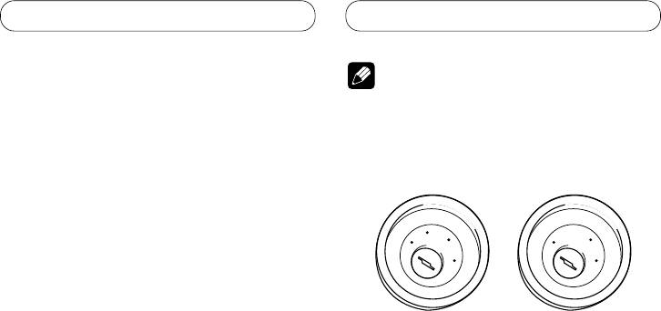
Note
Connecting the power cord
...............................
4
When connecting to
• When this unit is installed in a vehicle without
separately sold power amp ........................ 6
ACC (accessory) position on the ignition switch,
red cable must be wired to the terminal that can
Installation ............................................. 8
detect the operation of the ignition key. Otherwise,
DIN Front/Rear-mount ..................................... 8
battery drain may result.
Removing or attaching the trim ring ...................... 8
DIN Front-mount ...................................................... 8
C
A
C
O
O
F
N
F
N
DIN Rear-mount ....................................................... 9
F
F
O
O
S
S
Installing the microphone ............................... 9
T
T
A
A
R
R
When installing the microphone
T
T
on the sun visor ................................................... 9
When installing the microphone
on the steering column ..................................... 10
ACC position
No ACC position
Adjusting the microphone angle .......................... 10
Installing the steering remote control ......... 10
• Use this unit in other than the following
Installing the unit on a left-hand drive car ........... 11
conditions could result in fire or malfunction.
— Vehicles with a 12-volt battery and negative
grounding.
— Speakers with 50 W (output value) and 4 ohm
to 8 ohm (impedance value).
• To prevent short-circuit, overheating or
malfunction, be sure to follow the directions
below.
— Disconnect the negative terminal of the
battery before installation.
— Secure the wiring with cable clamps or
adhesive tape. To protect the wiring, wrap
adhesive tape around them where they lie
against metal parts.
— Place all cables away from moving parts, such
as gear shift and seat rails.
— Place all cables away from hot places, such as
near the heater outlet.
— Do not pass the yellow cable through a hole
into the engine compartment to connect to a
battery.
— Cover any disconnected cable connectors with
insulating tape.
— Do not shorten any cables.
— Never cut the insulation of the power cable of
this unit in order to share the power to other
equipment. Current capacity of the cable is
limited.
— Use a fuse of the rating prescribed.
— Never wire the speaker negative cable directly
to ground.
— Never band together multiple speaker’s
negative cables.
2
