Asus P4P8X: 2.4 Advanced menu
2.4 Advanced menu: Asus P4P8X
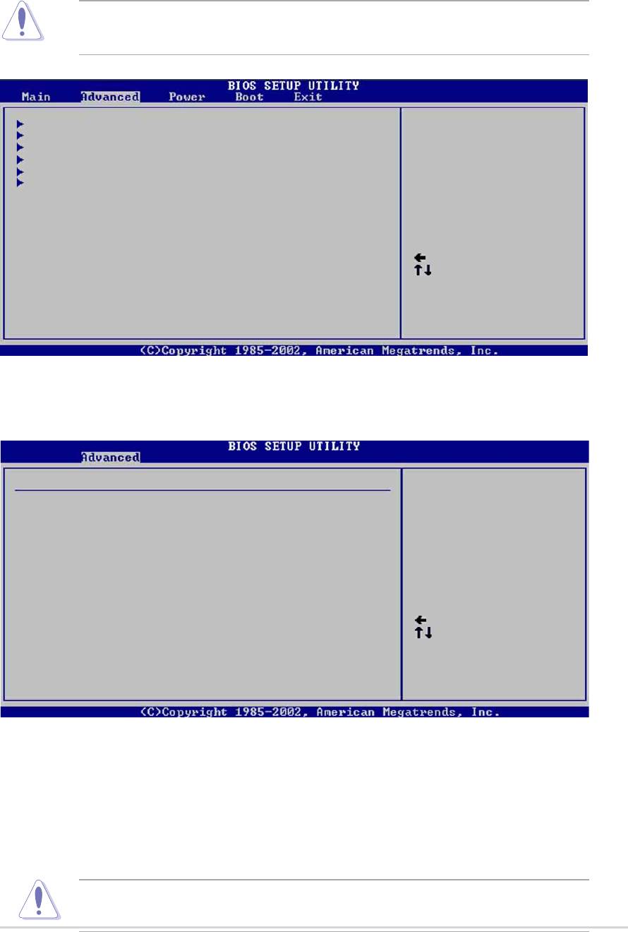
2.4 Advanced menu
The Advanced menu items allow you to change the settings for the CPU and other
system devices.
Take caution when changing the settings of the Advanced menu items.
Incorrect field values may cause the system to malfunction.
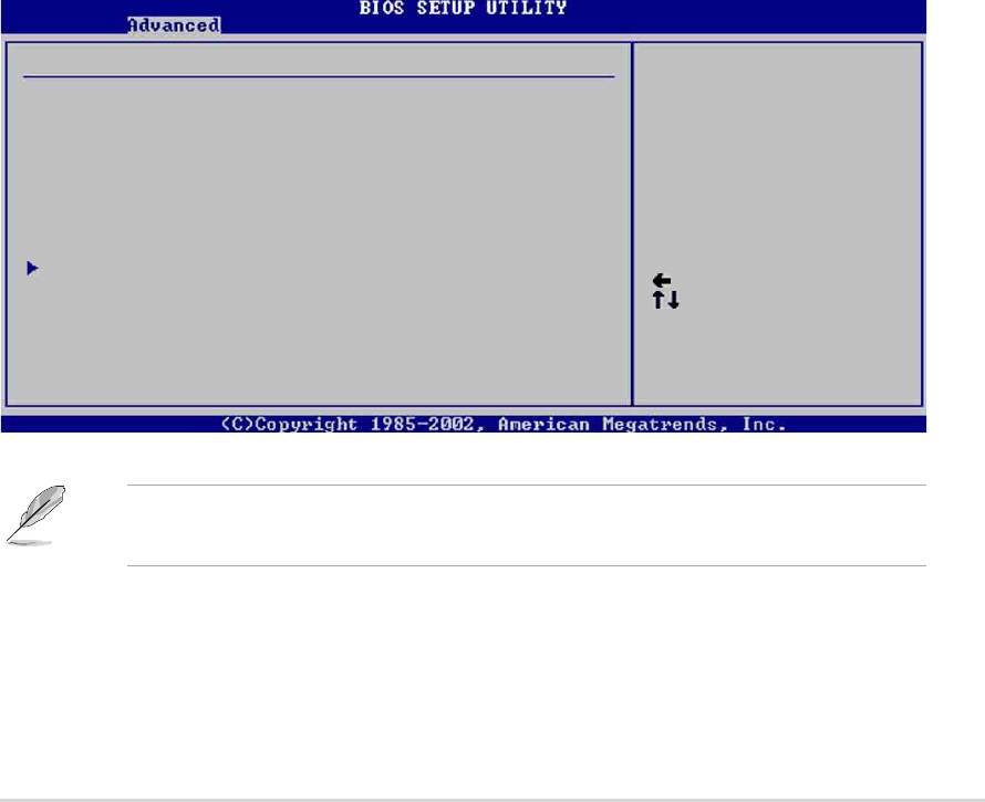
Jumperfree Configuration
Configure CPU.
CPU Configuration
Chipset
Onboard Devices Configuration
PCI PnP
USB Configuration
Select Screen
Select Item
Enter Go to Sub-screen
F1 General Help
F10 Save and Exit
ESC Exit
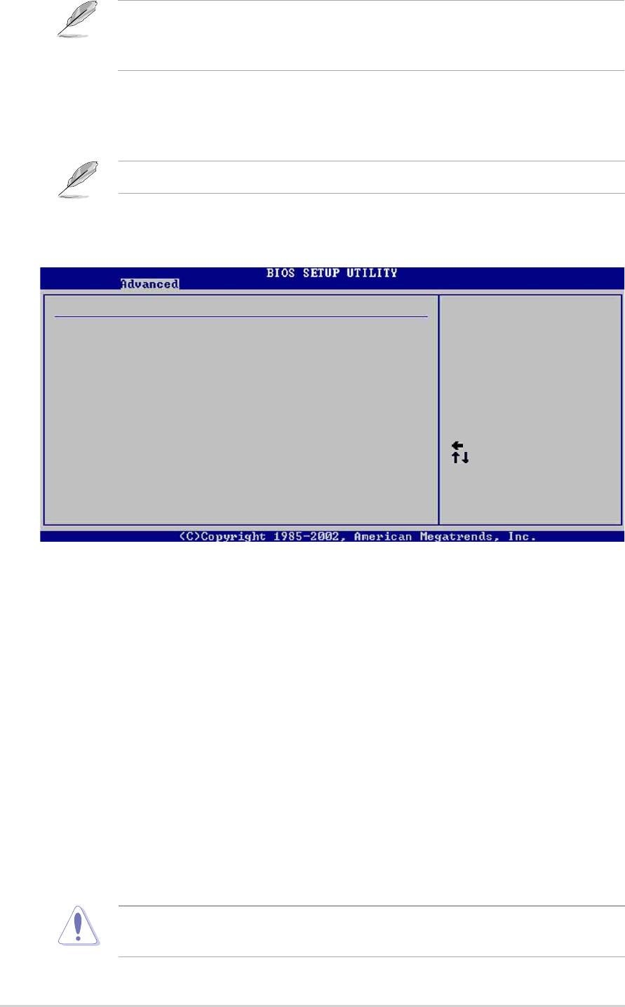
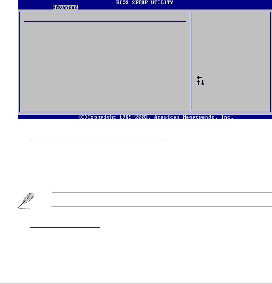
2.4.1 JumperFree Configuration
Configure System Frequency/Voltage
AI Overclock Tuner [Standard]
CPU Ratio [12]
Select Screen
Select Item
+- Change Option
F1 General Help
F10 Save and Exit
ESC Exit
AI Overclock Tuner [Standard]
Allows selection of CPU overclocking options to achieve desired CPU internal
frequency. Select either one of the preset overclocking options. Configuration
options: [Manual] [Standard] [Overclock 5%] [Overclock 10%] [Overclock 20%]
[Overclock 30%]
Selecting a very high CPU frequency may cause the system to become
unstable! If this happens, revert to the default setting.
ASUS P4P8X motherboard user guide
2-15
If you are using an unlocked CPU, the item CPU Ratio appears under the AI
Overclock Tuner item. You may select your desired ratio from the available
options.
CPU Ratio [12]
This field sets the ratio between the CPU Core Clock and the Front Side Bus (FSB)
Frequency.
If an invalid ratio is set in CMOS, the actual and setpoint values may differ.
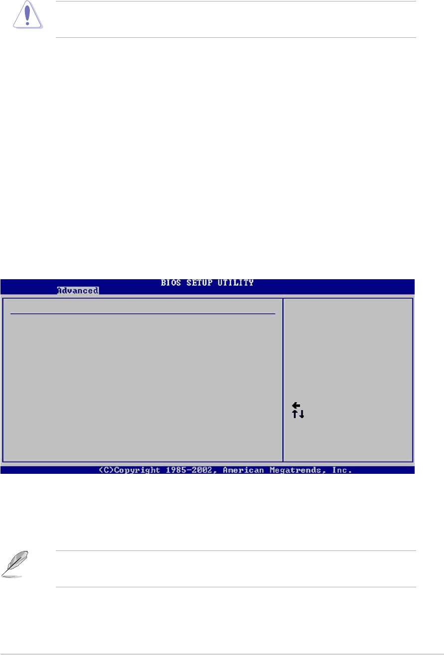
When you set the AI Overclocking Tuner item to [Manual], the related
overclocking items appear.
Configure System Frequency/Voltage
AI Overclock Tuner [Manual]
CPU External Frequency (MHz) [100]
CPU Ratio [12]
DRAM Frequency [Auto]
AGP/PCI Frequency (MHz) [Auto]
CPU VCore Offset to .IV [Disabled]
DDR Reference Voltage [Auto]
AGP VDDQ Voltage [1.50V]
Select Screen
Select Item
+- Change Option
F1 General Help
F10 Save and Exit
ESC Exit
CPU External Frequency (MHz) [XXX] (value is auto-detected)
Indicates the frequency sent by the clock generator to the system bus and PCI
bus. The bus frequency (external frequency) multiplied by the bus multiple equals
the CPU speed. The value of this item is auto-detected by BIOS and is not
manually configurable. The values range from 100 to 400. Refer to the following
table for the correct Front Side Bus and CPU External Frequency settings.
DRAM Frequency [Auto]
Allows you to set the DDR operating frequency. Configuration options: [266 MHz]
[333 MHz] [400 MHz] [Auto]
AGP/PCI Frequency (MHz) [Auto]
Allows you to adjust to a higher AGP/PCI frequency for better system performance
and overclocking capability. Configuration options: [Auto] [66.66/33.33] [72.73/
36.36] [80.00/40.00]
Selecting a very high AGP/PCI frequency may cause the system to become
unstable! If this happens, revert to the default setting.
2-16
Chapter 2: BIOS information
CPU VCore Voltage [Auto]
Allows you to select a specific CPU VCore voltage. Configuration options: [Auto]
[1.6000V] ... [1.4750V]
Refer to the CPU documentation before setting the CPU VCore voltage. A very
high Vcore voltage may severely damage the CPU!
DDR Reference Voltage [Auto]
Allows selection of the DDR SDRAM operating voltage. Configuration options:
[2.85V] [2.75V] [2.65V] [2.55V] [Auto]
AGP VDDQ voltage [1.50V]
Allows selection of the AGP operating voltage. Configuration options: [1.80V]
[1.70V] [1.60V] [1.50V]
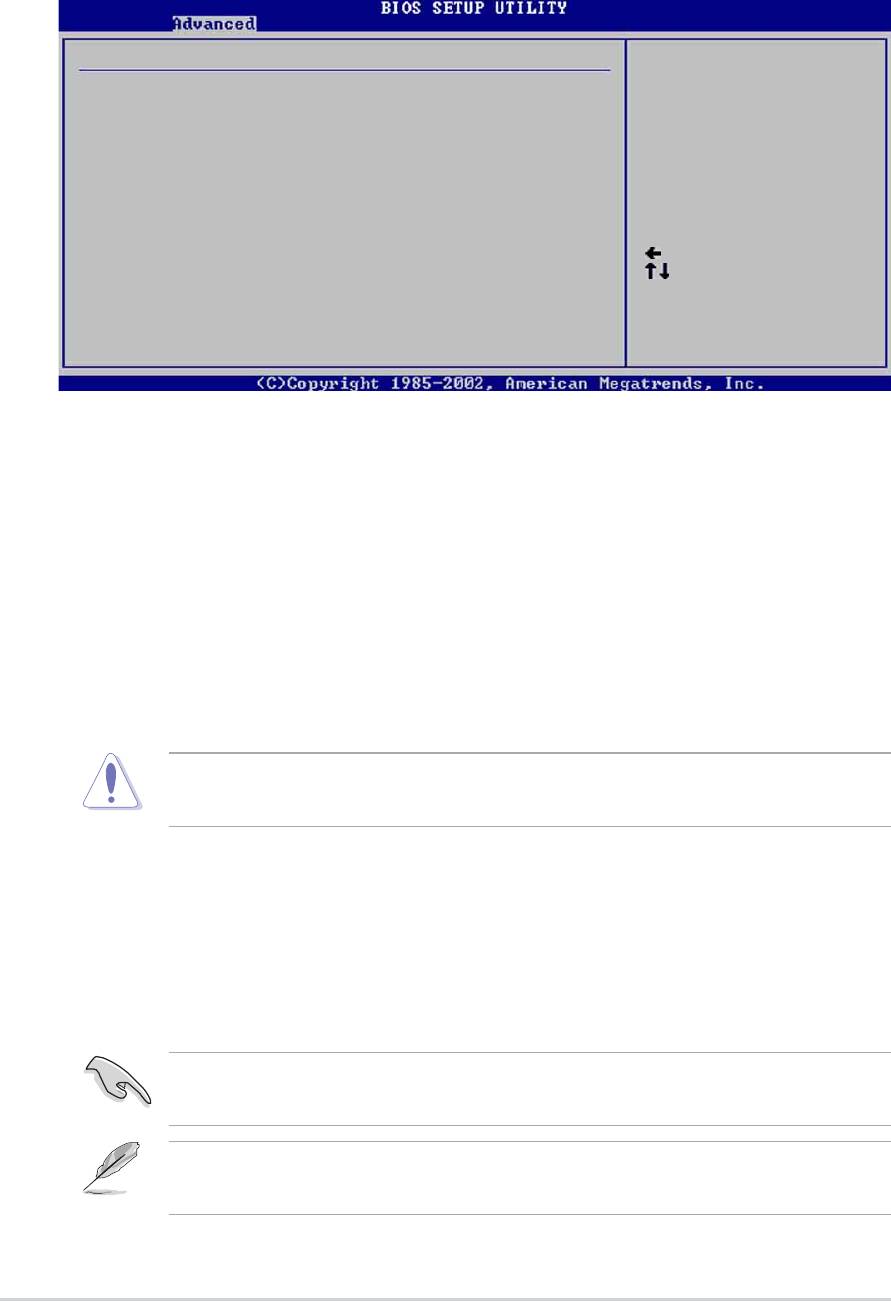
2.4.2 CPU Configuration
The items in this menu show the CPU-related information auto-detected by BIOS.
Configure advanced CPU settings
Manufacturer : Intel(R)
Brand String : Intel(R) Pentium(R) 4 CPU 2.4GHz
Frequency : 1800 MHz
Ratio Status : Locked
Ratio Actual Value : 18
CPU Ratio [18]
Hyper Threading Technology [Enabled]
Select Screen
Select Item
+- Change Option
F1 General Help
F10 Save and Exit
ESC Exit
Hyper-Threading Technology [Enabled]
This item allows you to enable or disable the processor Hyper-Threading
Technology. Configuration options: [Disabled] [Enabled]
The item Hyper-Threading Technology appears only if you installed an Intel
Pentium 4 CPU that supports this feature.
ASUS P4P8X motherboard user guide
2-17
2.4.3 Chipset
The Chipset menu items allow you to change the advanced chipset settings. Select
an item then press Enter to display the sub-menu.
Advanced Chipset settings
WARNING: Setting wrong values in the sections below
may cause system to malfunction.
Configure DRAM Timing by SPD [Enabled]
Memory Acceleration Mode [Auto]
DRAM Idle Timer [Auto]
DRAm Refresh Rate [Auto]
Graphic Adapter Priority [AGP/PCI]
Graphics Aperture Size [ 64 MB]
Spread Spectrum [Enabled]
Select Screen
Select Item
ICH Delayed Transaction [Enabled]
+- Change Option
F1 General Help
MPS Revision [1.4]
F10 Save and Exit
ESC Exit
Configure DRAM Timing by SPD [Enabled]
When this item is enabled, the DRAM timing parameters are set according to the
DRAM SPD (Serial Presence Detect). When disabled, you can manually set the
DRAM timing parameters through the DRAM sub-items. Configuration options:
[Disabled] [Enabled]
Memory Acceleration Mode [Auto]
This field when [Enabled] minimize latencies from CPU to memory to boost system
performance. Configuration options: [Auto] [Enabled]
Setting to [Enabled] may cause the system to become unstable! If this
happens, revert to the default setting [Auto].
DRAM Idle Timer [Auto]
Configuration options: [Infinite] [0T] [8T] [16T] [64T] [Auto]
DRAM Refresh Mode [Auto]
Configuration options: [Auto] [15.6 uSec] [7.8 uSec] [64 uSec] [64T]
If the system becomes unstable after changing the settings of any of the above
items, revert to the default settings.
The following sub-items appear only when the item Configure DRAM Timing
by SPD is set to Disabled.
2-18
Chapter 2: BIOS information

DRAM CAS# Latency [2.5 Clocks]
This item controls the latency between the SDRAM read command and the
time the data actually becomes available. Configuration options: [2.0 Clocks]
[2.5 Clocks] [3.0 Clocks]
DRAM RAS# Precharge [4 Clocks]
This item controls the idle clocks after issuing a precharge command to the
DDR SDRAM. Configuration options: [4 Clocks] [3 Clocks]
[2 Clocks]
DRAM RAS# to CAS# Delay [4 Clocks]
This item controls the latency between the DDR SDRAM active command and
the read/write command. Configuration options:
[4 Clocks] [3 Clocks] [2 Clocks]
DRAM Precharge Delay [8 Clocks]
Configuration options: [8 Clocks] [7 Clocks] [6 Clocks] [5 Clocks]
DRAM Burst Length [4 Clocks]
Configuration options: [4 Clocks] [8 Clocks]
Graphic Adapter Priority [AGP/PCI]
Allows selection of the graphics controller to use as primary boot device.
Configuration options: [AGP/PCI] [PCI/AGP]
Graphics Aperture Size [64MB]
Allows you to select the size of mapped memory for AGP graphic data.
Configuration options: [4MB] [8MB] [16MB] [32MB] [64MB] [128MB] [256MB]
Spread Spectrum [Enabled]
This field enables or disables the clock generator spread spectrum. Configuration
options: [Disabled] [Enabled]
ICH Delayed Transaction [Enabled]
Configuration options: [Disabled] [Enabled]
MPS Revision [1.1]
Configuration options: [1.1] [1.4]
ASUS P4P8X motherboard user guide
2-19

2.4.4 Onboard Devices Configuration
OnBoard AC’97 Audio [Auto]
OnBoard LAN [Enabled]
OnBoard LAN Boot ROM [Disabled]
Serial Port1 Address [3F8/IRQ4]
Serial Port2 Address [2F8/IRQ3]
Parallel Port Address [378]
Parallel Port Mode [ECP]
ECP Mode DMA Channel [DMA3]
Parallel Port IRQ [IRQ7]
OnBoard Game/MIDI Port [Disabled]
Select Screen
Select Item
+- Change Option
F1 General Help
F10 Save and Exit
ESC Exit
OnBoard AC’97 Audio [Auto]
[Auto] allows the BIOS to detect whether you are using any audio device. If an
audio device is detected, the onboard audio controller is enabled; if no audio
device is detected, the controller is disabled. Configuration options: [Disabled]
[Auto]
OnBoard LAN [Enabled]
Allows you to enable or disable the onboard LAN controller. Configuration options:
[Disabled] [Enabled]
OnBoard LAN Boot ROM [Disabled]
Allows you to enable or disable the option ROM in the onboard LAN controller.
This item appears only when the Onboard LAN item is set to Enabled.
Configuration options: [Disabled] [Enabled]
Serial Port1 Address [3F8/IRQ4]
Allows you to select the Serial Port1 base address. Configuration options:
[Disabled] [3F8/IRQ4] [3E8/IRQ4] [2E8/IRQ3]
Serial Port2 Address [2F8/IRQ3]
Allows you to select the Serial Port2 base address. Configuration options:
[Disabled] [2F8/IRQ3] [3E8/IRQ4] [2E8/IRQ3]
Parallel Port Address [378]
Allows you to select the Parallel Port base addresses. Configuration options:
[Disabled] [378] [278] [3BC]
2-20
Chapter 2: BIOS information

Parallel Port Mode [ECP]
Allows you to select the Parallel Port mode. When the item Parallel Port Address
is set to 278, the Parallel Port Mode options are only Normal and EPP.
Configuration options: [Normal] [Bi-directional] [EPP] [ECP]
EPP Version [1.9]
Allows selection of the Parallel Port EPP version. This item appears only when
the Parallel Port Mode is set to EPP. Configuration options: [1.9] [1.7]
ECP Mode DMA Channel [DMA3]
Allows selection of the Parallel Port ECP DMA channel. This item appears only
when the Parallel Port Mode is set to ECP. Configuration options: [DMA0]
[DMA1] [DMA3]
Parallel Port IRQ [IRQ7]
Allows you to select the Parallel Port IRQ. Configuration options: [IRQ5] [IRQ7]
Onboard Game/MIDI Port [Disabled]
Allows you to select the Game Port address or to disable the port. Configuration
options: [Disabled] [200/300] [200/330] [208/300] [208/330]
ASUS P4P8X motherboard user guide
2-21
2.4.5 PCI PnP
The PCI PnP menu items allow you to change the advanced settings for PCI/PnP
devices. The menu includes setting IRQ and DMA channel resources for either
PCI/PnP or legacy ISA devices, and setting the memory size block for legacy ISA
devices.
Take caution when changing the settings of the PCI PnP menu items.
Incorrect field values may cause the system to malfunction.
Advanced PCI/PnP settings
NO: Lets the bIOS
WARNING: Setting wrong values in the sections below
configure all the
may cause system to malfunction.
devices in the system.
YES: Lets the
Plug and Play OS [No]
operating system
PCI Latency Timer [64]
configure Plug and
Allocate IRQ to PCI VGA [Yes]
Play (PnP) devices not
Palette Snooping [Disabled]
required for boot if
PCI IDE BusMaster [Enabled]
your system has a Plug
IRQ3 [Available]
and Play operating
IRQ4 [Available]
system.
IRQ5 [Available]
Select Screen
IRQ7 [Available]
Select Item
IRQ9 [Available]
+- Change Option
IRQ10 [Available]
F1 General Help
IRQ11 [Available]
F10 Save and Exit
IRQ14 [Available]
ESC Exit
IRQ15 [Available]
Scroll down to display the rest of the menu items
Plug and Play O/S [No]
When set to [No], BIOS configures all the devices in the system. When set to [Yes]
and if you installed a Plug & Play operating system, the operating system
configures the Plug & Play devices not required for boot. Configuration options:
[No] [Yes]
PCI Latency Timer [64]
Allows you to select the value in units of PCI clocks for the PCI device latency
timer register. Configuration options: [32] [64] [96] [128] [160] [192] [224] [248]
Allocate IRQ to PCI VGA [Yes]
When set to [Yes], BIOS assigns an IRQ to PCI VGA card if the card requests for
an IRQ. When set to [No], BIOS does not assign an IRQ to the PCI VGA card even
if requested. Configuration options: [No] [Yes]
Pallete Snooping [Disabled]
When set to [Enabled], the pallete snooping feature informs the PCI devices that
an ISA graphics device is installed in the system so that the latter can function
correctly. Setting to [Disabled] deactivates this feature. Configuration options:
[Disabled] [Enabled]
2-22
Chapter 2: BIOS information
PCI IDE BusMaster [Enabled]
Allows BIOS to use PCI bus mastering when reading/writing to IDE devices.
Configuration options: [Disabled] [Enabled]
IRQ xx [Available]
When set to [Available], the specific IRQ is free for use of PCI/PnP devices. When
set to [Reserved], the IRQ is reserved for legacy ISA devices. Configuration
options: [Available] [Reserved]
DMA Channel xx [Available]
When set to [Available], the specific DMA channel is free for use of PCI/PnP
devices. When set to [Reserved], the DMA channel is reserved for legacy ISA
devices. Configuration options: [Available] [Reserved]
Reserved Memory Size [Disabled]
Sets the size of memory block reserved for legacy ISA devices. Configuration
options: [Disabled] [16K] [32K] [64K]
2.4.6 USB Configuration
The items in this menu allows you to change the USB-related features. Select an
item then press Enter to display the configuration options.
USB Configuration
Enables USB host
controllers.
Module Version : 2.22.4-5.3
USB Devices Enabled : None
USB Function [8 USB Ports]
Legacy USB Support [Auto]
USB 2.0 Controller [Enabled]
USB 2.0 Controller Mode [HiSpeed]
USB Mass Storage Device Configuration
Select Screen
Select Item
+- Change Option
F1 General Help
F10 Save and Exit
ESC Exit
The Module Version and USB Devices Enabled items show the auto-detected
values. If no USB device is detected, the item shows None.
USB Function [8 USB Ports]
Allows you to set the number of USB ports to activate. Before using the USB 2.0
feature, make sure that the USB 2.0 driver is installed. Configuration options:
[Disabled] [2 USB Ports] [4 USB Ports] [6 USB Ports] [8 USB Ports]
ASUS P4P8X motherboard user guide
2-23
Legacy USB Support [Auto]
Allows you to enable or disable support for legacy USB devices. Setting to Auto
allows the system to detect the presence of USB devices at startup. If detected,
the USB controller legacy mode is enabled. If no USB device is detected, the
legacy USB support is disabled. Configuration options: [Disabled] [Enabled] [Auto]
USB 2.0 Controller [Enabled]
Allows you to enable or disable the USB 2.0 controller. Configuration options:
[Disabled] [Enabled[
USB 2.0 Controller Mode [HiSpeed]
Allows you to configure the USB 2.0 controller in HiSpeed (480 Mbps) or Full
Speed (12 Mbps). Configuration options: [HiSpeed ] [Full Speed]
USB Mass Storage Device Configuration
USB Mass Storage Device Configuration
Number of seconds
POST waits for the USB
USB Mass Storage Reset Delay [20 Sec]
mass storage device
after that start unit
No USB Mass Storage device detected
command.
Device #1 N/A
Emulation Type [N/A]
Device #2 N/A
Emulation Type [N/A]
Device #3 N/A
Emulation Type [N/A]
Device #4 N/A
Select Screen
Emulation Type [N/A]
Select Item
Device #5 N/A
+- Change Option
Emulation Type [N/A]
F1 General Help
Device #6 N/A
F10 Save and Exit
Emulation Type [N/A]
ESC Exit
USB Mass Storage Reset Delay [20 Sec]
Allows you to select the number of seconds POST waits for the USB mass
storage device after the start unit command. The message “No USB mass
storage device detected” appears if none is installed in the system.
Configuration options: [10 Sec ] [20 Sec] [30 Sec] [40 Sec]
The Device items appear only when there are installed USB devices.
Emulation Type [N/A]
When set to Auto, USB devices less than 530MB will be emulated as floppy
drive, and the remaining drives as hard drives. Forced FDD option can be used
to force an HDD formatted drive to boot as FDD (for example, ZIP drive).
2-24
Chapter 2: BIOS information
Оглавление
- Contents
- Notices
- Safety information
- About this guide
- ASUS contact information
- P4P8X specifications summary
- P4P8X specifications summary
- 1.1 Welcome!
- 1.3 Special features
- 1.4 Motherboard components
- 1.5 Motherboard layout
- 1.6 Before you proceed
- 1.7 Motherboard installation
- 1.8 Central Processing Unit (CPU)
- 1.9 System memory
- 1.10 Expansion slots
- 1.11 Jumpers
- 1.12 Connectors
- 2.1 Managing and updating your BIOS
- 2.2 BIOS Setup program
- 2.3 Main menu
- 2.4 Advanced menu
- 2.5 Power menu
- 2.6 Boot menu
- 2.7 Exit menu
- 3.1 Install an operating system
- 3.3 Software information
