Asus P4P8X: 1.12 Connectors
1.12 Connectors: Asus P4P8X
1.12 Connectors
This section describes and illustrates the internal connectors on the motherboard.
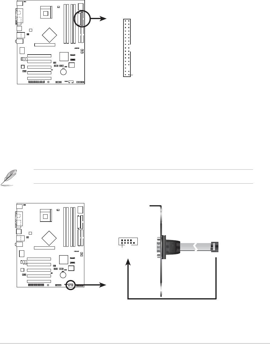
1. Floppy disk drive connector (34-1 pin FLOPPY1)
This connector supports the provided floppy drive ribbon cable. After
connecting one end to the motherboard, connect the other end to the floppy
drive. (Pin 5 is removed to prevent incorrect insertion when using ribbon cables
with pin 5 plug).
P4P8X
2. Serial port 1 connector (10-1 pin COM2)
This connector accommodates a second serial port using an optional serial
port bracket. Connect the bracket cable to this connector then install the
bracket into a slot opening at the back of the system chassis.
The serial port (COM2) bracket is purchased separately.
ASUS P4P8X motherboard user guide
1-21
®
NOTE: Orient the red markings o
n
FLOPPY1
the floppy ribbon cable to PIN 1.
PIN 1
P4P8X Floppy Disk Drive Connector
P4P8X
®
COM2
PIN 1
P4P8X Serial COM2 Bracket
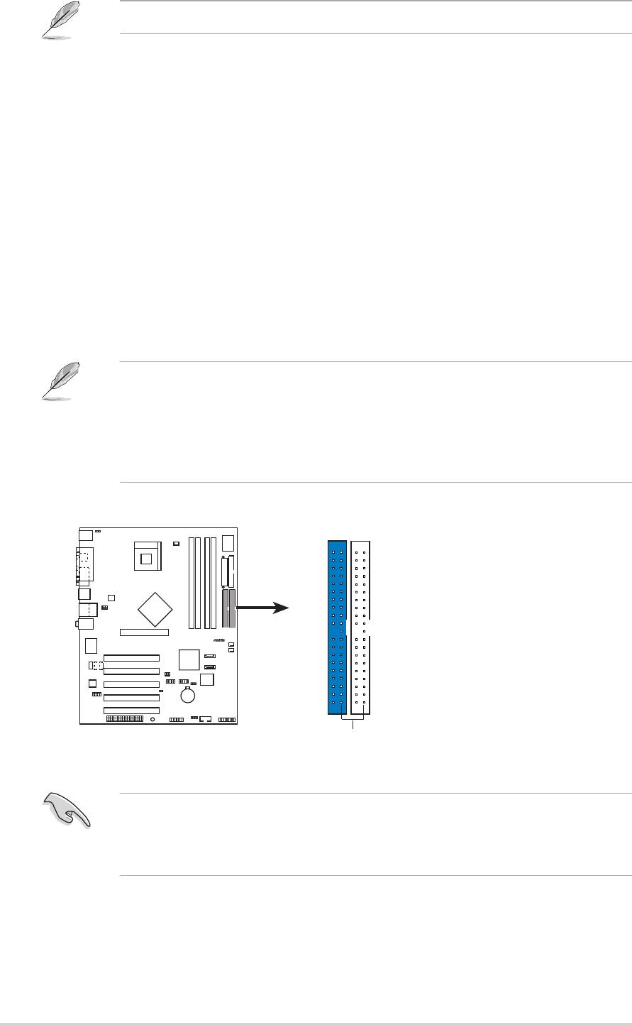
3. IDE connectors (40-1 pin PRI_IDE1, SEC_IDE1)
This connector supports the provided UltraDMA100/66 IDE ribbon cable. Connect
the cable’s blue connector to the primary (recommended) or secondary IDE
connector, then connect the gray connector to the UltraDMA100/66 slave device
(hard disk drive) and the black connector to the UltraDMA100/66 master device. It
is recommended that you connect non-UltraDMA100/66 devices to the secondary
IDE connector. If you install two hard disks, you must configure the second drive
as a slave device by setting its jumper accordingly. Refer to the hard disk
documentation for the jumper settings. BIOS supports specific device bootup. If
you have more than two UltraDMA100/66/33 devices, purchase another
UltraDMA100/66/33 cable. You may configure two hard disks to be both master
devices with two ribbon cables – one for the primary IDE connector and another
for the secondary IDE connector.
P4P8X
1-22
Chapter 1: Product introduction
®
NOTE: Orient the red marking
P4P8X IDE Connectors
s
Refer to the Parallel ATA and Serial ATA device configurations on the next page.
1. Pin 20 on each IDE connector is removed to match the covered hole on the
UltraDMA cable connector. This prevents incorrect orientation when you
connect the cables.
2. The hole near the blue connector on the UltraDMA100/66 cable is intentional.
3. For UltraDMA100/66 IDE devices, use the 80-conductor IDE cable.
(usually zigzag) on the IDE
ribbon cable to PIN 1.
PRI_IDE1
SEC_IDE1
PIN 1
Important note when using legacy OS
Refer to page 1-22 on how to configure P-ATA and S-ATA devices if you
installed a legacy operating system (e.g. MS-DOS, Windows 98/Me/NT4.0).
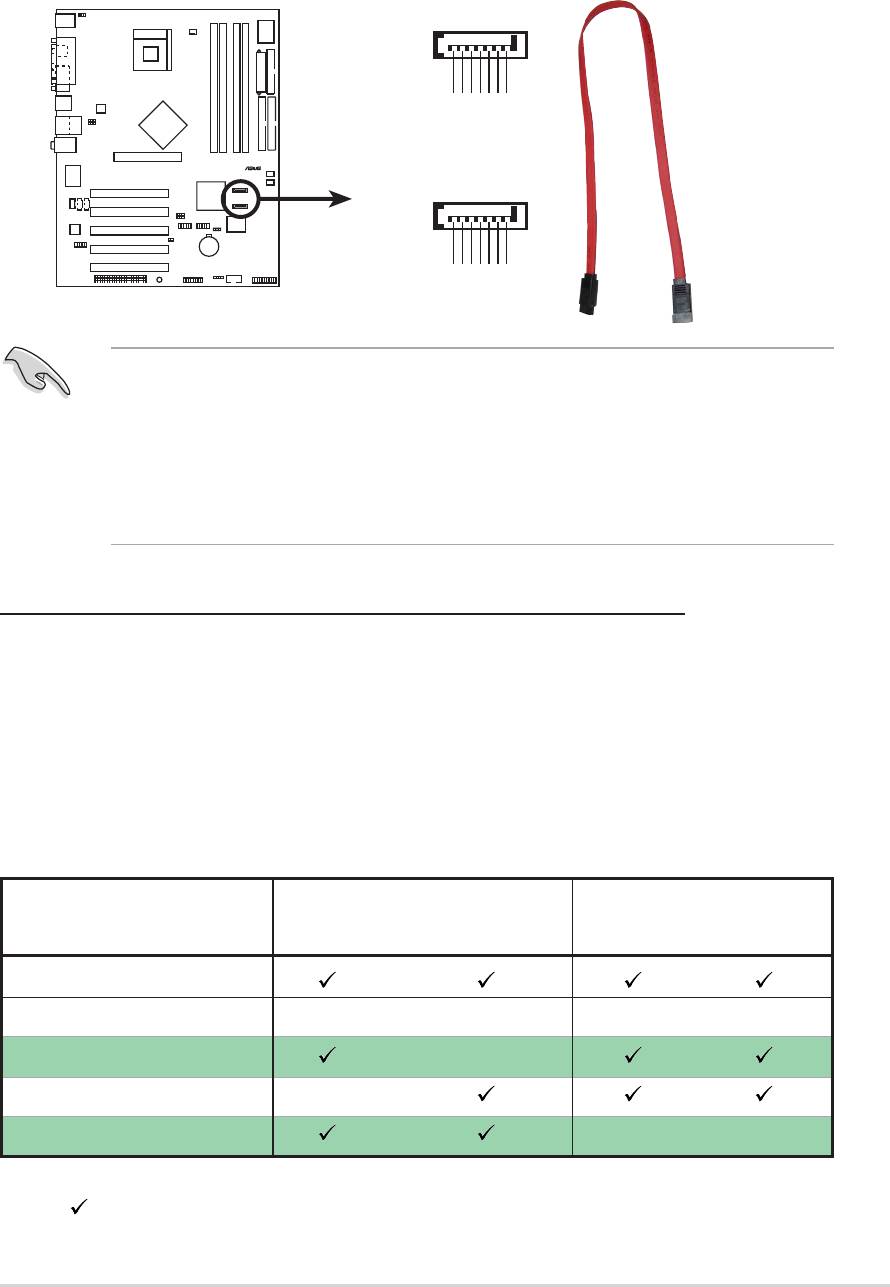
4. Serial ATA connectors (7-pin SATA1, SATA2)
These next generation connectors support the thin Serial ATA cables for Serial ATA
hard disks. The current Serial ATA interface allows up to 150 MB/s data transfer
rate, faster than the standard parallel ATA with 133 MB/s (Ultra ATA/133).
P4P8X
ASUS P4P8X motherboard user guide
1-23
®
SATA1
GND
GND
GND
RSATA_TXP1
RSATA_TXN1
RSATA_RXP1
RSATA_RXN1
SATA2
GND
GND
GND
P4P8X SATA Connectors
RSATA_TXP2
RSATA_TXN2
RSATA_RXP2
RSATA_RXN2
Important notes on Serial ATA solution:
• In legacy operating system (Win98, WinME, WinNT, DOS) environment,
using SATA will disable one of the IDE channels from ICH5 south bridge
chipset. See BIOS section for correct settings.
• Hot plug support for Serial ATA drive and connections are not available in
this motherboard.
Parallel ATA and Serial ATA device configurations
Following are the Parallel ATA and Serial ATA device configurations supported by
Intel ICH5 specifications.
Native operating systems (OS) are Windows 2000/XP. ICH5 supports a maximum
of six (6) devices using these OS.
Legacy OS are MS-DOS, Windows 98/Me/NT4.0. ICH5 supports a maximum of
four (4) devices using these OS.
P-ATA S-ATA
Operating System Primary Secondary Port 0 Port 1
(2 devices) (2 devices) (1 device) (1 device)
1. Windows 2000/XP
2. Windows 98/Me/NT4.0
Configuration A —
Configuration B —
Configuration C ——
Legend:
Supported
— Disabled
Required IDE Configuration settings in BIOS
Refer to the following table for the appropriate BIOS settings of the above P-ATA
and S-ATA device configurations. See section “2.3.6 IDE Configuration” for details
on the related BIOS items.
Windows Windows 98/Me/NT4.0
BIOS item 2000/XP A B C
Onboard IDE Operate Mode Enhanced Mode Compatible Mode Compatible Mode Compatible Mode
Enhanced Mode Support On S-ATA — — —
IDE Port Settings — Primary P-ATA+S-ATA Sec. P-ATA+S-ATA P-ATA Ports Only
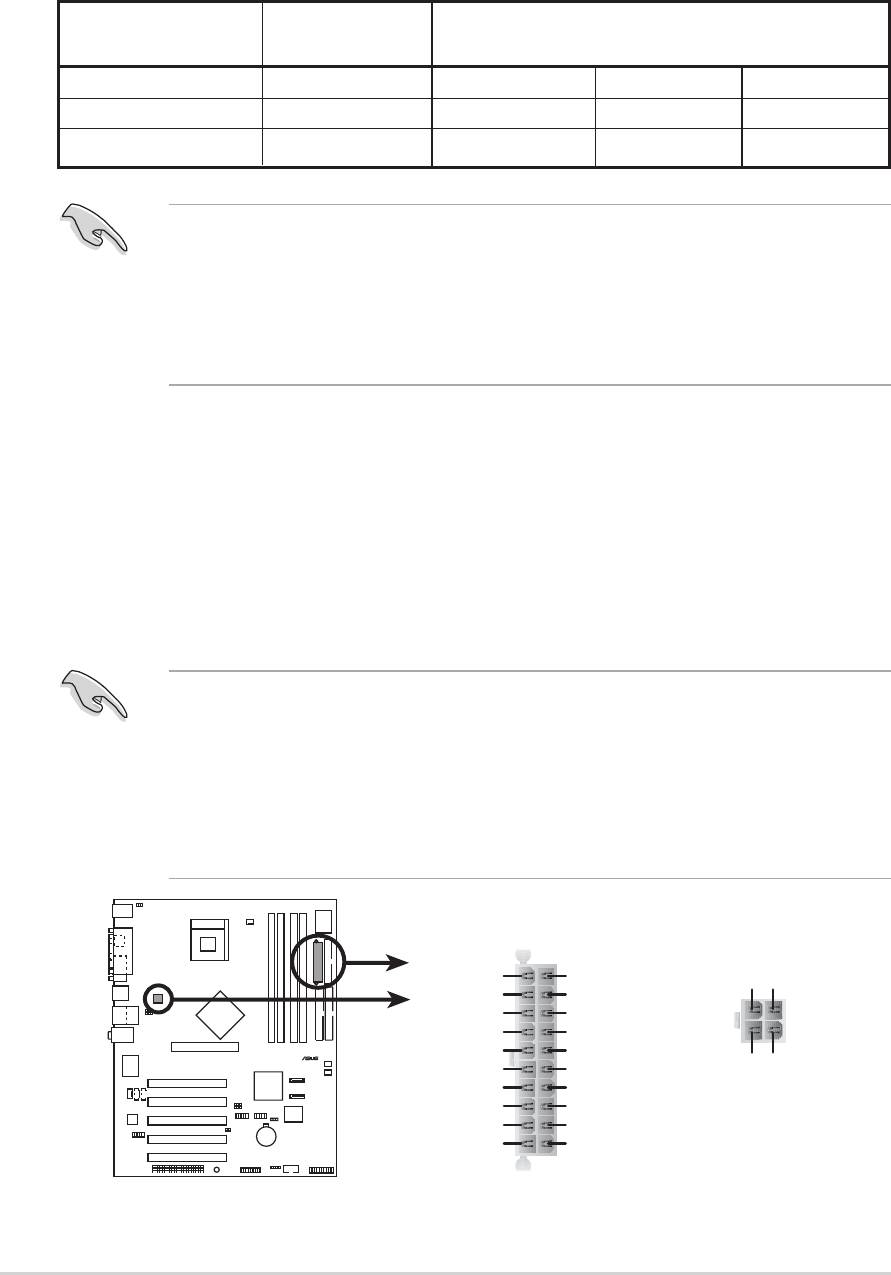
5. ATX power connectors (20-pin ATXPWR1, 4-pin ATX12V1)
These connectors connect to an ATX 12V power supply. The plugs from the
power supply are designed to fit these connectors in only one orientation. Find
the proper orientation and push down firmly until the connectors completely fit.
In addition to the 20-pin ATXPWR1 connector, this motherboard requires that
you connect the 4-pin ATX +12V power plug to provide sufficient power to the
CPU.
• Do not forget to connect the 4-pin ATX +12V power plug. Otherwise, the
system will not boot up.
• Make sure that your ATX 12V power supply can provide 8A on the +12V
lead and at least 1A on the +5-volt standby lead (+5VSB). The minimum
recommended wattage is 230W, or 300W for a fully configured system. The
system may become unstable and may experience difficulty powering up if
the power supply is inadequate.
P4P8X
1-24
Chapter 1: Product introduction
®
®
• When using Serial ATA function, make sure that the Windows
XP™
Service Pack 1 is installed.
• When using Serial ATA hard disks in a legacy operating system
(Windows 98, 98SE, ME, NT, DOS) make sure to adjust the appropriate
BIOS settings. Refer to section “2.3.6 IDE Configuration” in page 2-12 for
more detailed setting information.
ATXPWR1 ATX12V1
+3.3VDC
+3.3VDC
+12V DC GND
-12.0VDC
+3.3VDC
COM
COM
PS_ON#
+5.0VDC
COM
COM
COM
+5.0VDC
+12V DC GND
COM
COM
-5.0VDC
PWR_OK
+5.0VDC
+5VSB
+5.0VDC
+12.0VDC
P4P8X ATX Power Connector
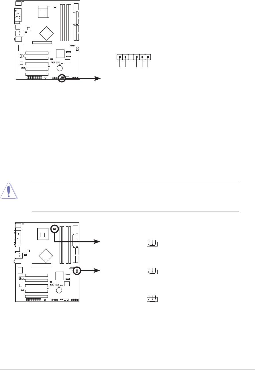
6. SMBus connector (6-1 pin SMB1)
This connector allows you to connect SMBus (System Management Bus)
devices. Devices communicate with an SMBus host and/or other SMBus
devices using the SMBus interface.
P4P8X
ASUS P4P8X motherboard user guide
1-25
®
SMB1
1
+3V
Ground
SMBCLK
P4P8X SMBus Connector
FLOATING
SMBDATA
7. CPU and chassis fan connectors (3-pin CPU_FAN1, CHA_FAN1,
PWR_FAN1)
The fan connectors support cooling fans of 350mA~740mA (8.88W max.) or a
total of 1A~2.22A (26.64W max.) at +12V. Connect the fan cables to the fan
connectors on the motherboard, making sure that the black wire of each cable
matches the ground pin of the connector.
Do not forget to connect the fan cables to the fan connectors. Lack of sufficient
air flow within the system may damage the motherboard components. These
are not jumpers! DO NOT place jumper caps on the fan connectors!
P4P8X
®
GND
Rotatio
CPU_FAN1
CHA_FAN1
P4P8X 12-Volt Fan Connectors
n
+12V
GND
+12V
Rotation
GND
+12V
Rotation
PWR_FAN1
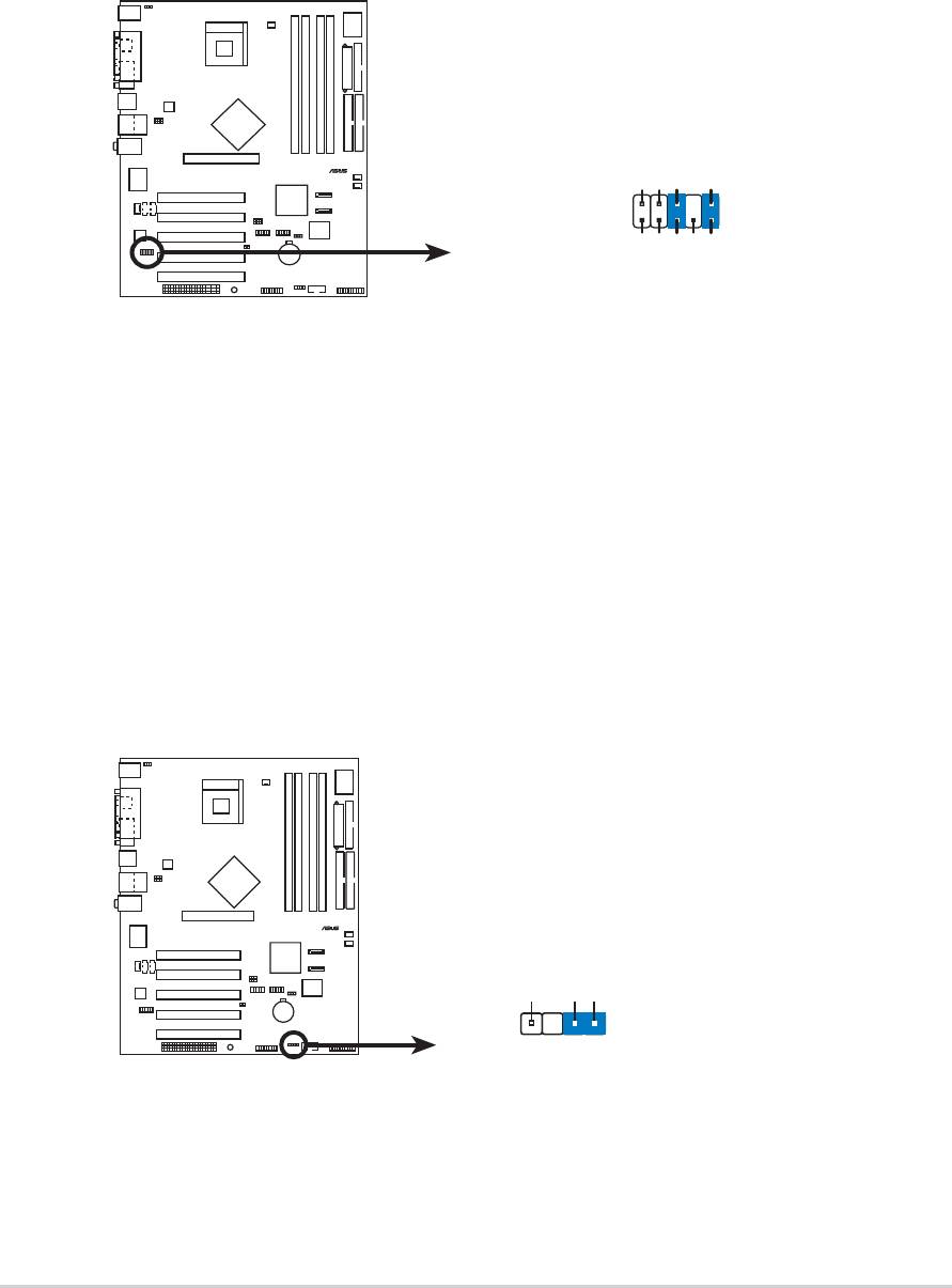
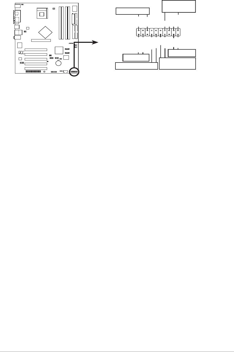
8. Front panel audio connector (10-1 pin FP_AUDIO)
This is an interface for the Intel front panel audio cable that allow convenient
connection and control of audio devices.
By default, the pins labeled LINE OUT_R/BLINE_OUT_R and the pins LINE
OUT_L/BLINE_OUT_L are shorted with jumper caps. Remove the caps only
when you are connecting the front panel audio cable.
9. Chassis intrusion connector (4-1 pin CHASSIS1)
This lead is for a chassis designed with intrusion detection feature. This
requires an external detection mechanism such as a chassis intrusion sensor
or microswitch. When you remove any chassis component, the sensor triggers
and sends a high-level signal to this lead to record a chassis intrusion event.
By default, the pins labeled “Chassis Signal” and “Ground” are shorted
with a jumper cap. If you wish to use the chassis intrusion detection
feature, remove the jumper cap from the pins.
P4P8X
1-26
Chapter 1: Product introduction
®
CHASSIS
P4P8X Chassis Alarm Lead
1
+5VSB_MB
Chassis Signal
GND
(Default
)
P4P8X
®
AGND
+5VA
BLINE_OUT_R
BLINE_OUT_L
FP_AUDIO
NC
MIC2
MICPWR
Line out_R
Line out_L
P4P8X Front Panel Audio Connector
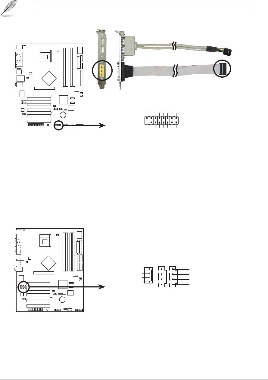
10. GAME/MIDI connector (16-1 pin GAME1)
This connector supports an optional GAME/MIDI module. Connect the GAME/
MIDI cable to this connector. The GAME/MIDI port on the module connects a
joystick or a game pad for playing games, and MIDI devices for playing or
editing audio files.
The USB 2.0/GAME module is purchased separately.
P4P8X
ASUS P4P8X motherboard user guide
1-27
®
+5V
J1B2
J1CY
GND
GND
J1CX
J1B1
+5V
GAME1
P4P8X Game Connector
+5V
J2B2
J2CY
J2CX
J2B1
MIDI_IN
MIDI_OUT
11. Internal audio connectors (4-pin CD1, AUX1, MODEM)
These connectors allow you to receive stereo audio input from sound sources
such as a CD-ROM, TV tuner, or MPEG card. The MODEM connector allows
the onboard audio to interface with a voice modem card with a similar
connector. It also allows the sharing of mono_in (such as a phone) and a
mono_out (such as a speaker) between the audio and a voice modem card.
P4P8X
®
Right Audio Channe
CD1(Black) AUX1(White)
P4P8X Internal Audio Connectors
l
MODEM
Modem-Out
Ground
Ground
Ground
Ground
Modem-In
Left Audio Channel
12. USB header (10-1 pin USB56, USB78)
If the USB ports on the rear panel are inadequate, two USB headers are
available for additional USB ports. The USB header complies with USB 2.0
specification that supports up to 480 Mbps connection speed. This speed
advantage over the conventional 12 Mbps on USB 1.1 allows faster Internet
connection, interactive gaming, and simultaneous running of high-speed
peripherals.
Connect an optional USB 2.0/GAME module to this header. The module has
two USB 2.0 ports that support the next generation USB peripherals such as
high resolution cameras, scanners, and printers.
You must install the driver before you can use the USB 2.0 capability.
P4P8X
The USB 2.0/GAME module is purchased separately.
1-28
Chapter 1: Product introduction
®
USB+5V
USB_P6-
USB_P6+
GND
NC
USB+5V
USB_P8-
USB_P8+
GND
NC
USB56
USB78
1
1
P4P8X USB 2.0 Header
GND
GND
USB+5V
USB_P5-
USB+5V
USB_P5+
USB_P7-
USB_P7+
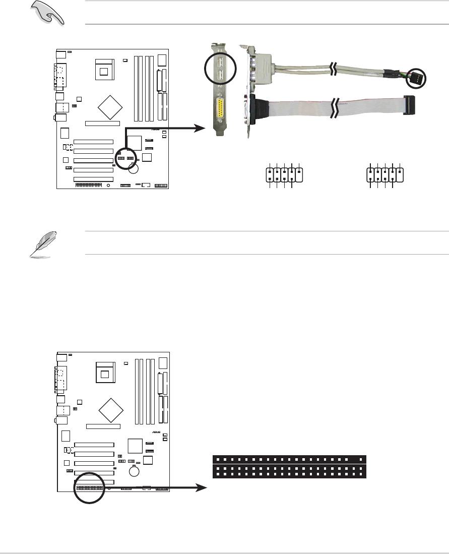
13. WiFi connector (63-pin WIFI)
This slot supports the ASUS proprietary WiFi (Wireless Fidelity) module.
P4P8X
®
WIF
P4P8X Wi-Fi Slot
I
14. System panel connector (20-pin PANEL1)
This connector accommodates several system front panel functions.
P4P8X
ASUS P4P8X motherboard user guide
1-29
®
*
Requires an ATX power supply
P4P8X System Panel Connectors
.
Speaker
Connector
Power LED
PLED+
PLED-
+5V
Ground
Ground
Speaker
PWR
Reset
ExtSMI#
Ground
Ground
Ground
IDE_LED+
IDE_LED-
Reset SW
IDE_LED
ATX Power
SMI Lead
Switch*
• System Power LED Lead (3-1 pin PLED)
This 3-1 pin connector connects to the system power LED. The LED lights up
when you turn on the system power, and blinks when the system is in sleep
mode.
• Hard disk activity LED (2-pin IDELED)
This 2-pin connector supplies power to the hard disk activity LED. The read
and write activities of any device connected to the primary or secondary IDE
connector cause this LED to light up.
• System Warning Speaker Lead (4-pin SPEAKER)
This 4-pin connector connects to the case-mounted speaker and allows you to
hear system beeps and warnings.
• System Management Interrupt Lead (2-pin SMI)
This 2-pin connector allows you to manually place the system into a suspend
mode, or “green” mode, where system activity is instantly decreased to save
power and to expand the life of certain system components. Attach the case-
mounted suspend switch to this 2-pin connector.
• ATX Power Switch / Soft-Off Switch Lead (2-pin PWR)
This connector connects a switch that controls the system power. Pressing the
power switch turns the system between ON and SLEEP, or ON and SOFT
OFF, depending on the BIOS or OS settings. Pressing the power switch while
in the ON mode for more than 4 seconds turns the system OFF.
• Reset Switch Lead (2-pin RESET)
This 2-pin connector connects to the case-mounted reset switch for rebooting
the system without turning off the system power.

1-30
Chapter 1: Product introduction
Chapter 2
This chapter tells how to change system settings
through the BIOS Setup menus. Detailed
descriptions of the BIOS parameters are also
provided.
BIOS information
Оглавление
- Contents
- Notices
- Safety information
- About this guide
- ASUS contact information
- P4P8X specifications summary
- P4P8X specifications summary
- 1.1 Welcome!
- 1.3 Special features
- 1.4 Motherboard components
- 1.5 Motherboard layout
- 1.6 Before you proceed
- 1.7 Motherboard installation
- 1.8 Central Processing Unit (CPU)
- 1.9 System memory
- 1.10 Expansion slots
- 1.11 Jumpers
- 1.12 Connectors
- 2.1 Managing and updating your BIOS
- 2.2 BIOS Setup program
- 2.3 Main menu
- 2.4 Advanced menu
- 2.5 Power menu
- 2.6 Boot menu
- 2.7 Exit menu
- 3.1 Install an operating system
- 3.3 Software information
