Asus P4P8X: 1.4 Motherboard components
1.4 Motherboard components: Asus P4P8X

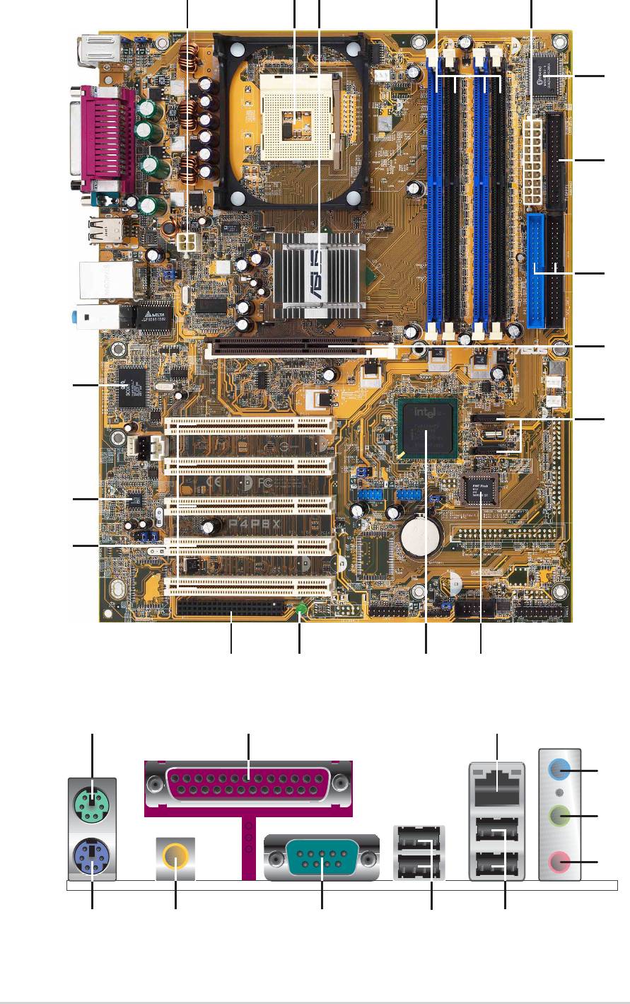
1.4 Motherboard components
Before you install the motherboard, learn about its major components and
available features to facilitate the installation and future upgrades. Refer to the
succeeding pages for the component descriptions.
1. ATX 12V connector
17. LAN controller
2. CPU socket
18. PS/2 mouse port
3. North Bridge controller
19. Parallel port
4. DDR DIMM sockets
20. RJ-45 port
5. ATX power connector
21. Line In jack
6. Super I/O controller
22. Line Out jack
7. Floppy disk connector
23. Microphone jack
8. IDE connectors
24. USB 2.0 ports 3 and 4
9. AGP 8X slot
25. USB 2.0 ports 1 and 2
10. SATA connectors
26. Serial port
11. Flash ROM
27. S/PDIF out port
12. South Bridge controller
28. Keyboard port
13. Standby power LED
14. WiFi slot
15. PCI slots
16. Audio CODEC
See page 1-6 for the specifications of each component.
ASUS P4P8X motherboard user guide
1-5
1-6
Chapter 1: Product introduction
43
17
2
12
5
8
16
15
11
1
7
9
1
13
0
6
14
18
2
28
1
2
2
2
3
24
19 20
2627
25

ATX 12V connector. This power connector connects the 4-pin 12V plug from
1
the ATX 12V power supply.
2
CPU socket. A 478-pin surface mount, Zero Insertion Force (ZIF) socket for
®
®
the Intel
Pentium
4 Processor, with 800/533/400 MHz system bus that allows
4.3GB/s, and 3.2GB/s data transfer rates, respectively.
®
3
North bridge controller. The Intel
82865P Memory Controller Hub (MCH)
provides the processor interface with 533/400 MHz frequency, system
memory interface at 333/266MHz operation and an AGP interface that
supports AGP 3.0 specification including 8X Fast Write protocol. The MCH
®
interconnects to the south bridge ICH5 via the Intel
proprietary Hub Interface.
DDR DIMM sockets. These four 184-pin DIMM sockets support up to 4GB
4
system memory using unbuffered non-ECC PC2700/2100 DDR DIMMs.
5
ATX power connector. This 20-pin connector connects to an ATX power
supply. The power supply must have at least 1A on the +5V standby lead
(+5VSB).
Super I/O controller. This Winbond Low Pin Count (LPC) interface provides
6
the commonly used Super I/O functionality. The chipset supports a high-
performance floppy disk controller for a 360K/720K/1.44M/2.88M floppy disk
drive, a multi-mode parallel port, two standard compatible UARTs, and a Flash
ROM interface. This controller also integrates the ASIC for PC health
monitoring.
7
Floppy disk connector. This connector accommodates the provided ribbon
cable for the floppy disk drive. One side of the connector is slotted to prevent
incorrect insertion of the floppy disk cable.
8
IDE connectors. These dual-channel bus master IDE connectors support
Ultra DMA100/66, PIO Modes 3 & 4 IDE devices. Both the primary (blue) and
secondary (black) connectors are slotted to prevent incorrect insertion of the
IDE ribbon cable.
9
AGP 8X slot. This Accelerated Graphics Port (AGP) slot supports 0.8V/1.5V
AGP 8X mode graphics cards for 3D graphical applications.
10
SATA connectors. These connectors support Serial ATA HDDs and allows
for up to 150MB/s data transfer rate, faster than the standard Parallel ATA
with 133 MB/s.
11
Flash ROM. This 4Mb firmware contains the programmable BIOS program.
South bridge controller. The fifth-generation Intel I/O Controller Hub (ICH5)
12
is a subsystem that integrates various I/O functions including 2-channel
ATA100 bus master IDE controller, up to eight USB 2.0/1.1 ports, I/O APIC,
SMBus 2.0 controller, LPC interface, AC’97 2.2 interface, and PCI 2.2
interface. The ICH5 also contains the necessary arbitration and buffering for
efficient utilization of these interfaces.
13
Standby power LED. This LED lights up if there is a standby power on the
motherboard. This LED acts as a reminder to turn off the system power before
plugging or unplugging devices.
ASUS P4P8X motherboard user guide
1-7
WiFi slot. The WiFi (Wireless Fidelity) slot connects a Wi-Fi certified
14
equipment for wireless networking that allows 11Mbps transmission (with a
fallback to 5.5, 2 and 1 Mbps) in the 2.4 GHz band. Wi-Fi networks use
radio technologies known as IEEE 802.11b to provide a fast reliable
wireless connectivity.
15
PCI slots. These five 32-bit PCI 2.2 expansion slots support bus master
PCI cards like SCSI or LAN cards with 133MB/s maximum throughput.
Audio CODEC. The ADI AD1985 is an AC’97 CODEC that allows 6-channel
16
audio playback. The audio CODEC provides six DAC channels for 5.1
surround sound, S/PDIF output, AUX and Line In stereo inputs, integrated
headphone amplifier, and supports greater than 90dB dynamic range.
®
LAN controller. This 3Com
3C940 Gbit PCI LAN controller support
17
10BASE/100BASE/1000BASE-TX networking.
18
PS/2 mouse port. This green 6-pin connector is for a PS/2 mouse.
Parallel port. This 25-pin port connects a parallel printer, a scanner, or other
19
devices.
RJ-45 port. This port allows connection to a Local Area Network (LAN)
20
through a network hub.
Line In jack. This Line In (light blue) jack connects a tape player or other
21
audio sources. In 6-channel mode, the function of this jack becomes Rear
Speaker out.
22
Line Out jack. This Line Out (lime) jack connects a headphone or a
speaker. In 6-channel mode, the function of this jack becomes Front
Speaker Out.
23
Microphone jack. This Mic (pink) jack connects a microphone. In 6-channel
mode, the function of this jack becomes Bass/Center Speaker Out.
The functions of the Line Out, Line In, and Microphone jacks change when you
select the 6-channel audio configuration as shown in the following table:
Audio 2, 4 or 6-channel configuration
Headphone/
2-Speaker 4-Speaker 6-Speaker
Light Blue Line In Rear Speaker Out Rear Speaker Out
Lime Line Out Front Speaker Out Front Speaker Out
Pink Mic In Mic In Bass/Center Speaker Out
24
USB 2.0 ports 3 and 4. These two 4-pin Universal Serial Bus (USB) ports
are available for connecting USB 2.0 devices.
25
USB 2.0 ports 1 and 2. These two 4-pin Universal Serial Bus (USB) ports
are available for connecting USB 2.0 devices.
26
Serial port. This 9-pin COM1 port is for pointing devices or other serial
devices.
27
S/PDIF jack. This jack connects to external audio output devices.
28
PS/2 keyboard port. This purple connector is for a PS/2 keyboard.
1-8
Chapter 1: Product introduction
Оглавление
- Contents
- Notices
- Safety information
- About this guide
- ASUS contact information
- P4P8X specifications summary
- P4P8X specifications summary
- 1.1 Welcome!
- 1.3 Special features
- 1.4 Motherboard components
- 1.5 Motherboard layout
- 1.6 Before you proceed
- 1.7 Motherboard installation
- 1.8 Central Processing Unit (CPU)
- 1.9 System memory
- 1.10 Expansion slots
- 1.11 Jumpers
- 1.12 Connectors
- 2.1 Managing and updating your BIOS
- 2.2 BIOS Setup program
- 2.3 Main menu
- 2.4 Advanced menu
- 2.5 Power menu
- 2.6 Boot menu
- 2.7 Exit menu
- 3.1 Install an operating system
- 3.3 Software information
