Pioneer A-20-S: Connecting up
Connecting up: Pioneer A-20-S
Table of contents
Connecting up
02
5
En
English
Deutsch
Français
Nederlands
Italiano
Español
Ру
сский
Chapter 2:
Connecting up
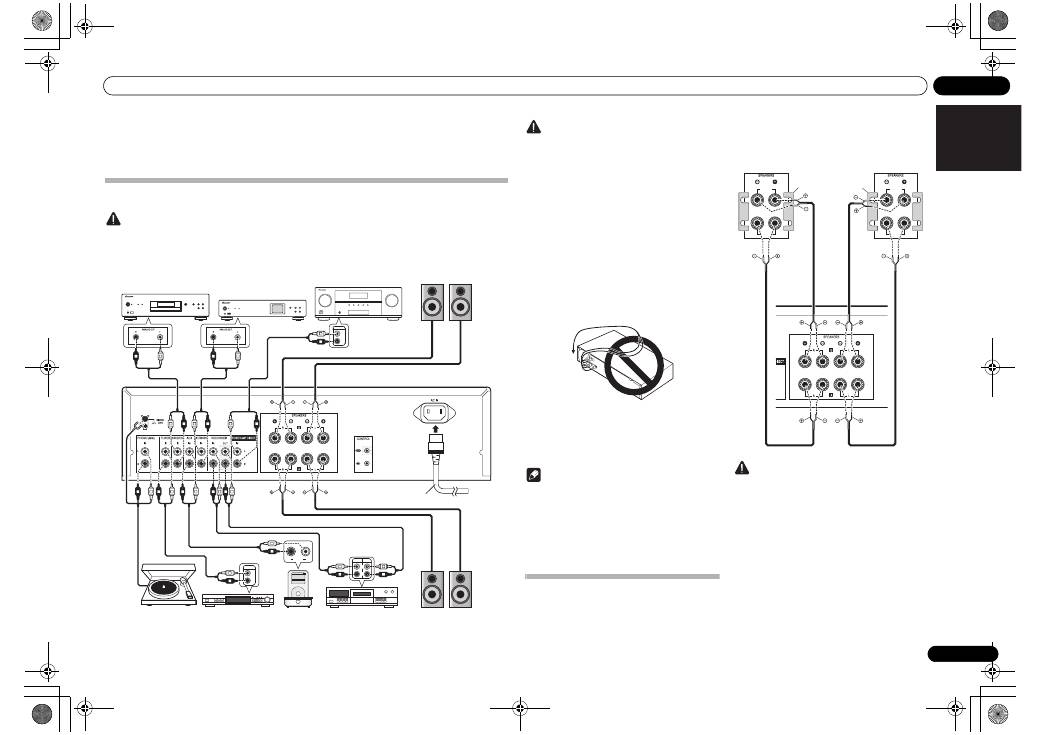
Making cable connections
Caution
• Before making or changing the connections, switch off the power and disconnect the power cord from the AC
outlet.
• Connect the power cord after all the connections between devices have been completed.
REC
R
L
OUTPUT
R
L
PLAY
R
L
AUDIO
OUTPUT
PRE OUT
R
L
L
R
L
R
L
R
L
R
L
R
L
R
L
R
L
R
L
R
L
R
L
R
L
R
L
R
L
R
L
R
MENU
iPod
Music>
Extras>
Settings>
Shuffle Songs
Backlight
SACD/CD player
Network audio player
PRE OUT jacks on pre-
amplifier or AV amplifier
Speaker system B
Speaker system A
Turntable
Tuner
iPod dock, etc
CD recorder or
tape deck
Right
Left
Right
Left
Power cord
(included)
A-30’s rear panel
A-30 only
Caution
• The
SIGNAL GND
terminal is provided to reduce
noise when connecting the unit to components
such as an analog turntable.
• Do not connect the
PHONO (MM)
terminals to any
component other than a turntable; also, do not
connect to a turntable equipped with built-in
equalizer. An excessively high sound output may be
produced, resulting in damage to your speakers or
other devices.
• The unit’s
PHONO (MM)
terminals are designed to
be used with turntables equipped with MM
(moving-magnet) type cartridges. Turntables
equipped with MC (moving-coil) cartridges cannot
be used.
• Make sure not to bend the cables over the top of
this unit (as shown in the illustration). If this
happens, the magnetic field produced by the
transformers in this unit may cause a humming
noise from the speakers.
• The unit’s
POWER AMP DIRECT
terminals should
never be connected to any other component’s
connectors except PRE-AMP OUT.
• If your turntable has a grounding wire, secure it to
the ground terminal on this amplifier.
Note
• When connecting a tape cassette deck, playback
noise may be heard, depending on the installation
location. This noise is caused by leakage flux from
the amplifier’s transformer. In this event, change
the installation location, or move the deck farther
from the amplifier.
• iPod is a trademark of Apple Inc., registered in the
U.S. and other countries.
About “Bi-wiring”
This unit can be used with speakers that support bi-
wiring. Be sure to connect the high-frequency and
low-frequency connections correctly.
• During playback, be sure that both the
SPEAKERS
A
button and
SPEAKERS B
button are set to ON
(page 7).
Caution
• When using bi-wiring to connect speakers, avoid
adverse affects on the amplifier by being sure to
remove the HIGH and LOW short bars provided
with the speakers. For detailed information, consult
the instructions provided with the speakers.
• When using speakers with removable network
circuits, note that if the network is removed, no
effect will be produced and damage may be caused
to the speaker.
• Another method of connection is to connect the
SPEAKERS A
terminals to HIGH and the
SPEAKERS B
terminals to LOW (reverse that shown
in the illustration).
HIGH
LOW
HIGH
LOW
Speaker system
Left
Speaker system
Right
A-30’s rear
panel
Remove the shorting
bar between the +
and – terminals.
A30_SYXE8.book 5 ページ 2012年2月16日 木曜日 午前8時58分
02
Connecting up
6
En
Connecting speaker cables
1
Twist the cable cores.
2
Loosen the nut on the SPEAKERS
terminal, and insert the speaker cable into
the exposed hole in the terminal shaft.
3
Retighten the terminal nut.
Caution
• When using only one set of speaker terminals
(SPEAKERS A or SPEAKERS B), or when utilizing
bi-wiring connections, the speaker used should
have a nominal impedance between 4
Ω
and
16
Ω
. When using both sets of terminals, the
connected speakers should have nominal
impedance between 8
Ω
and 32
Ω
. Consult the
instructions accompanying your speakers for
details regarding the impedance value.
• Make sure the positive and negative (+/–) terminals
on the amplifier match those on the speakers.
• These speaker terminals carry
HAZARDOUS live
voltage
. To prevent the risk of electric shock when
connecting or disconnecting the speaker cables,
disconnect the power cord before touching any
uninsulated parts.
• Make sure that all the bare speaker wire is twisted
together and inserted fully into the speaker
terminal. If any of the bare speaker wire touches the
back panel it may cause the power to cut off as a
safety measure.
Connecting audio cables
Connect the white plug to the left (L) jack, and the red
plug to the right (R) jack. Be sure to insert the plugs fully
into the jacks.
1
2
3
10 mm
Left (white)
Right (red)
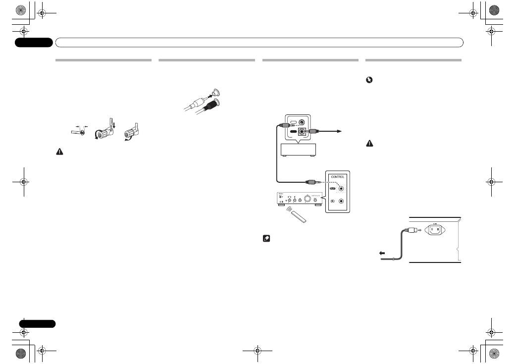
Using centralized control with other
Pioneer components (Except A-10)
Multiple Pioneer components equipped with
CONTROL
IN/OUT
jacks can be connected to the A-30/A-20 unit,
allowing centralized control of the components via the
remote sensor on the A-30/A-20. This also allows remote
control of components not equipped with a remote
sensor, or installed in places where the component’s
remote sensor cannot be accessed.
Note
• For connections use a commercially available
monaural miniplug cord (without resistor).
• When connecting the
CONTROL IN/OUT
jacks,
commercially available audio cords must also be
used to make analog connections. Merely
connecting the
CONTROL IN/OUT
jacks alone will
not allow proper system control.
• When a control cord is connected to the A-30/A-
20’s
CONTROL IN
jack, the unit cannot be
controlled by pointing the remote control at the A-
30/A-20 (the remote sensor is automatically
disabled).
Plugging in
Important
• When going on a trip or otherwise not using the
unit for an extended period, always disconnect the
power cord from its outlet. Note that various
internal settings will not be lost even if the power
cord is disconnected from its outlet for an extended
time.
• If it is necessary to detach the power cord, first be
sure to press the
/I STANDBY/ON
button on the
front panel of the unit so the A-30/A-20 is turned
OFF or the A-10 is in standby mode before
detaching the cord.
Caution
• The use of a power cord other than the one provided
will invalidate the warranty, since Pioneer will not
be responsible for any damage incurred. (The
power cord provided with the model A-30 has a
rated current capacity of 10 A, while the cord
provided with the A-20/A-10 has a rated current
capacity of 2.5 A.)
• Do not use any power cord other than the one
supplied with this unit.
• Do not use the supplied power cord for any purpose
other than that described below.
After you’ve finished making all connections, plug the
unit into an AC outlet.
1
Plug the supplied power cord into the
AC IN socket on the rear panel of the unit.
2
Plug the other end into an AC outlet.
IN
OUT
CONTROL
Other Pioneer
component equipped
with CONTROL IN/
OUT jacks
To other Pioneer
component
equipped with
CONTROL IN jack
A-30/A-20
Aim remote control
at the sensor on the
A-30/A-20.
A-30/A-20
remote
control
To AC outlet
Power cord
A-30’s rear panel
02_connecting_up.fm 6 ページ 2012年6月21日 木曜日 午後2時1分


