Dell Precision 650: Microprocessor
Microprocessor : Dell Precision 650
Back to Contents Page
Microprocessor
DellPrecision™Workstation650andDellPrecisionWorkstation450ServiceManual
Installation Guidelines
Installing the Microprocessor
Removing the Microprocessor
Installation Guidelines
l Your computer is designed for dual-processor operations. The heat sinks (CPU_0 and CPU_1) are keyed to fit their specific connector.
l For single-processor operations, the processor must be installed in socket CPU_0. The VRM for the single processor is already installed and cannot be
removed. Processor socket 1 and VRM connector 1 must be empty. To locate these components, see the system board components illustration (for the
Dell Precision 450 computer, see "System Board Components" or for the Dell Precision 650 computer, see "System Board Components") or the system
board label inside your computer.
l For dual-processor operations, both processor sockets and the VRM connector must be populated. To locate the VRM connector, see the system board
components illustration (for the Dell Precision 450 computer, see "System Board Components" or for the Dell Precision 650 computer, see "System Board
Components")or the system board label inside your computer.
l For dual-processor operations, the two processors and the VRMs must be identical. If the processors do not match, you receive a system message. If
the processors voltage don't match or the VRM is not properly installed, the diagnostic lights indicate an error..
l If you are upgrading your microprocessor, keep your original microprocessor heat sink and securing clips for future troubleshooting.
Installing the Microprocessor
1. Remove the microprocessor airflow shroud (for the Dell Precision 650 computer, see "Microprocessor Airflow Shroud — DellPrecision™650Computer" or
for the Dell Precision 450 computer, see "Microprocessor Airflow Shroud — DellPrecision™450Computer").
If you are replacing a microprocessor, see "Removing the Microprocessor."
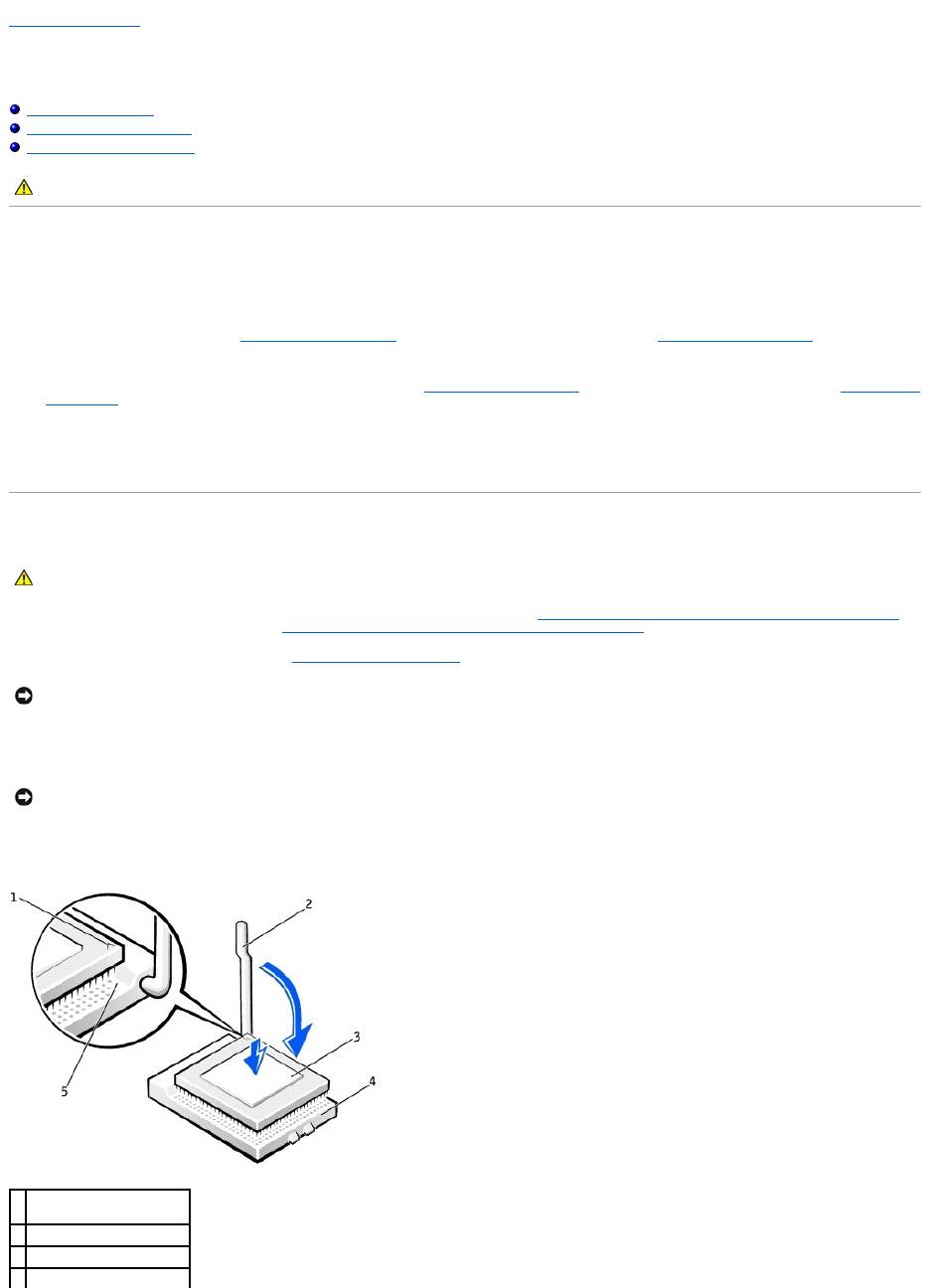
2. If the release lever is not extended to the release position, move it to that position.
3. Align pin-1 (the imprinted corner) of the microprocessor and pin-1 of the socket.
4. Carefully set the microprocessor in the socket and press it down lightly to seat it.
5. Rotate the release lever back toward the system board until it snaps into place, securing the microprocessor.
CAUTION: Before you begin any of the procedures in this section, follow the safety instructions in the System Information Guide.
CAUTION: The processor can get very hot during normal operation. Ensure that the processor has had sufficient time to cool before you touch it.
NOTICE: You must position the microprocessor correctly in the socket to avoid permanent damage to the microprocessor and the computer.
NOTICE: Microprocessor pins are delicate. To avoid damage, ensure that the microprocessor aligns properly with the socket, and do not use excessive
force when you install the processor.
1
microprocessor pin-1
indicator
2
release lever
3
microprocessor
4
microprocessor socket
6. Remove the thermal grease protective cover and place the heat sink in the base.
7. Place one end of the heat sink under the tab on the retention module on the side opposite the lever. Lower the heat sink onto the microprocessor so
that the heat sink fits securely under the tab on the other end of the retention module.
8. Replace the retention module clips.
9. If you installed a microprocessor replacement kit from Dell, return the original heat sink assembly and microprocessor to Dell in the same package in
which your replacement kit was sent.
10. If you are installing a second microprocessor, install the VRM.
11. Replace the airflow shroud (for the Dell Precision 650 computer, see "Microprocessor Airflow Shroud — DellPrecision™650Computer" or for the Dell
Precision 450 computer, see "Microprocessor Airflow Shroud — DellPrecision™450Computer").
12. Close the computer cover.
13. Connect your computer and devices to electrical outlets, and turn them on.
Removing the Microprocessor
1. Remove the microprocessor airflow shroud (for the Dell Precision 650 computer, see "Microprocessor Airflow Shroud — DellPrecision™650Computer" or
for the Dell Precision 450 computer, see "Microprocessor Airflow Shroud — DellPrecision™450Computer").
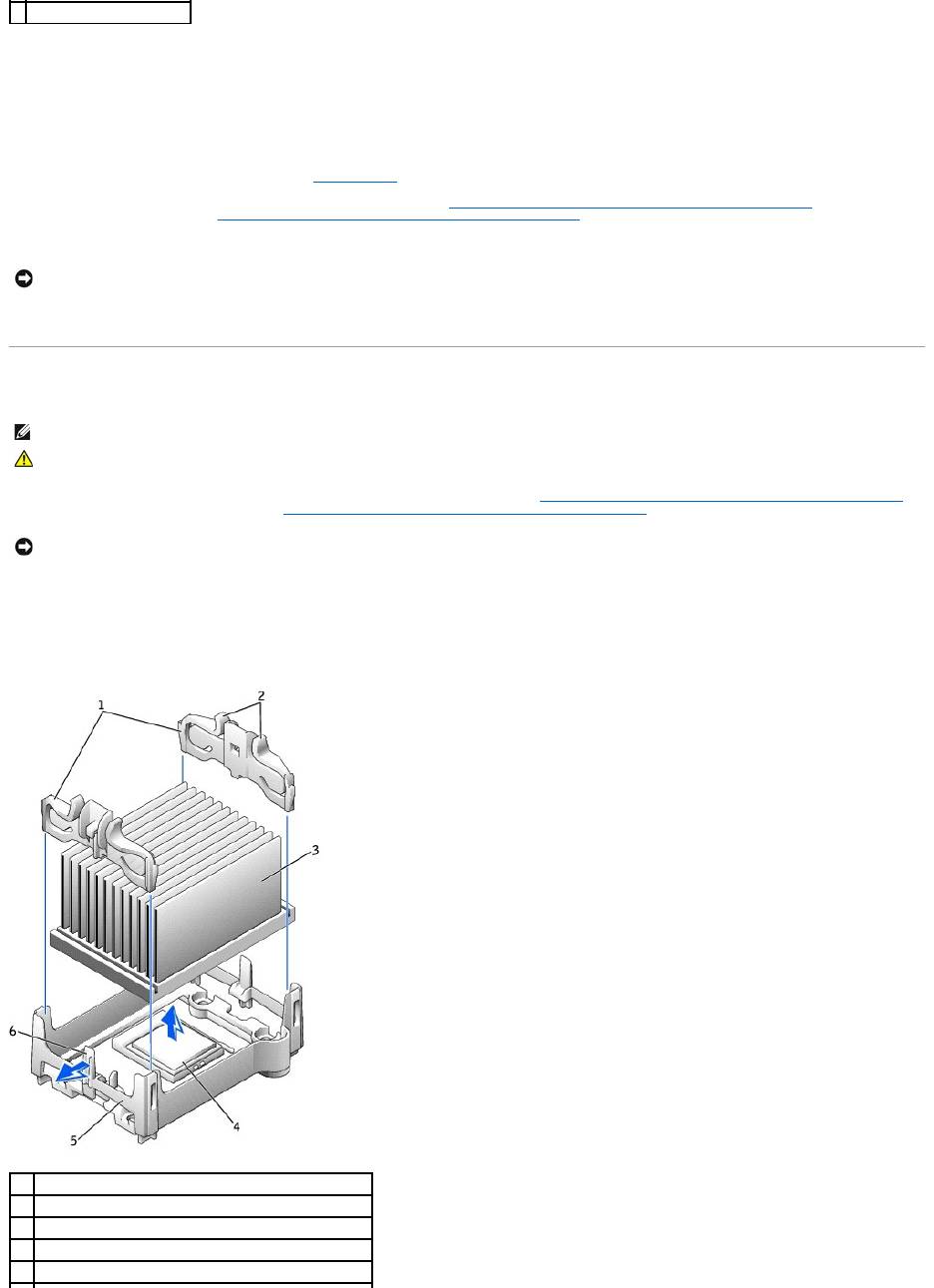
2. Remove the microprocessor heat sink:
a. Remove the two retention module clips by pressing the tabs together and lifting the retention module clips up.
b. Press the lever on the retention module until the heat sink is released.
c. Gently lift the heat sink away from the microprocessor.
5
socket pin-1 indicator
NOTICE: To connect a network cable, first plug the cable into the network wall jack and then plug it into the computer.
NOTE: It is recommended that only a technically knowledgeable person perform this procedure.
CAUTION: The processor can get very hot during normal operation. Ensure that the processor has had sufficient time to cool before you touch it.
NOTICE: If you are installing a microprocessor upgrade kit from Dell, discard the original heat sink. If you are not installing a microprocessor upgrade kit
from Dell, reuse the original heat sink when you install your new microprocessor.
1
retention module clips (2)
2
tabs (2 on each retention module clip)
3
heat sink
4
microprocessor socket
5
retention module
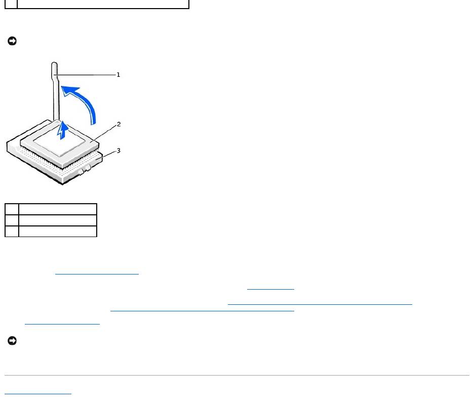
3. Pull the release lever straight up until the microprocessor is released.
4. Remove the microprocessor from the socket.
If you are replacing the microprocessor, leave the release lever extended in the release position so that the socket is ready for the new microprocessor
and go to "Installing the Microprocessor."
If you are removing a second microprocessor and not installing another one, remove the VRM and then continue with step 9.
5. Replace the airflow shroud (for the Dell Precision 650 computer, see "Microprocessor Airflow Shroud — DellPrecision™650Computer" or for the Dell
Precision 450 computer, see "Microprocessor Airflow Shroud — DellPrecision™450Computer").
6. Close the computer cover.
7. Connect your computer and devices to electrical outlets, and turn them on.
Back to Contents Page
6
lever
NOTICE: Be careful not to bend any of the pins when you remove the microprocessor from the socket. Bending the pins can permanently damage the
microprocessor.
1
release lever
2
microprocessor
3
socket
NOTICE: To connect a network cable, first plug the cable into the network wall jack and then plug it into the computer.
Оглавление
- DellPrecision™Workstation650andDellPrecisionWorkstation450 Service Manual
- Battery
- Before You Begin
- Cards
- Chassis Intrusion Switch
- Control Panel
- Inside Your Computer — DellPrecision™450Computer
- Drives — DellPrecision™450Computer
- Power Supply — DellPrecision™450Computer
- Drive Door — DellPrecision™650Computer
- Microprocessor Airflow Shroud — DellPrecision™450Computer
- Card Fan and Guide — Dell Precision 650 Computer
- Front Panel
- I/O Panel
- Inside Your Computer — DellPrecision™650Computer
- Closing the Computer Cover
- Opening the Computer Cover
- Microprocessor
- Drives — DellPrecision™650Computer
- VRM
- Memory
- Microprocessor Airflow Shroud — DellPrecision™650Computer
- Power Supply — DellPrecision™650Computer
- System Board
