Dell Precision 650: Drives — DellPrecision™650Computer
Drives — DellPrecision™650Computer : Dell Precision 650
Back to Contents Page
Drives — DellPrecision™650Computer
DellPrecision™Workstation650andDellPrecisionWorkstation450ServiceManual
Overview
Hard Drive
Floppy Drive
CD/DVD Drive
Overview
Your computer supports:
l Three hard drives
l One floppy drive
l Three CD or DVD drives
IDE Drive Addressing
When you connect two IDE devices to a single IDE interface cable and configure them for the cable select setting, the device attached to the last connector on
the interface cable is the primary (master) or boot device (drive 0), and the device attached to the middle connector on the interface cable is the secondary
(slave) device (drive 1). See the drive documentation in your upgrade kit for information on configuring devices for the cable select setting.
Since cable select is the default setting, any additional drives that are installed do not need to be set as a primary or secondary drive.
Your computer supports up to two IDE devices. Hard drives should be connected to the connector labeled "IDE1," and CD/DVD drives should be connected to
the connector labeled "IDE2."
Connecting Drive Cables
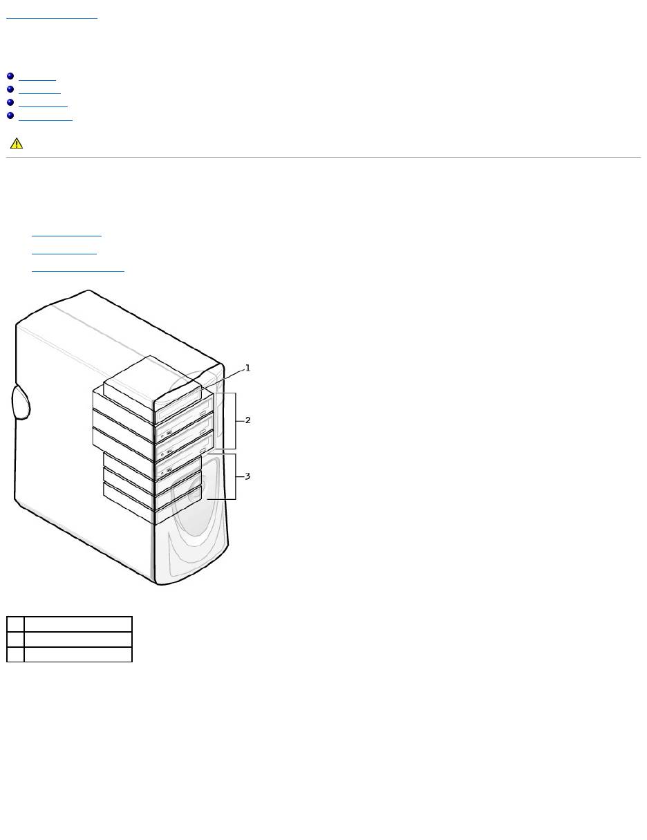
When you install a drive, you connect two cables—a DC power cable and an interface cable—to the back of the drive.
CAUTION: Before you begin any of the procedures in this section, follow the safety instructions in the System Information Guide.
1
floppy drive(s)
2
CD/DVD drive(s)
3
hard drive(s)
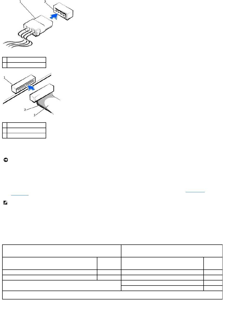
Most interface connectors are keyed for correct insertion; that is, a notch or a missing pin on one connector matches a tab or a filled-in hole on the other
connector. Keyed connectors ensure that the pin-1 wire in the cable (indicated by the colored stripe along one edge of the cable) goes to the pin-1 end of the
connector. The pin-1 end of a connector on a board or a card is usually indicated by a silk-screened "1" printed directly on the board or card.
SCSI Device Installation Guidelines
This section describes how to configure and install SCSI devices in your computer. To install a SCSI device, you can use one or both of the following SCSI
controllers:
l The SCSI connector on the system board. To locate the SCSI system board connector, see the system board illustration, see "System Board
Components" ) or the interior service label.
l A SCSI controller card installed in your computer.
SCSI ID Numbers
Internal SCSI devices must have a unique SCSI ID number from 0 to 15. If you are using the SCSI connector on the system board and a SCSI controller card
installed in your computer, you have two separate SCSI buses operating. Each SCSI bus has a set of SCSI ID numbers from 0 to 15.
When SCSI devices are shipped from the factory, the default SCSI ID numbers are assigned as follows:
SCSI devices installed by Dell are configured correctly during the manufacturing process. You do not need to set the SCSI ID for these SCSI devices.
1
power cable
2
power input connector
1
interface connector
2
colored stripe on cable
3
interface cable
NOTICE: When you connect an interface cable, do not place the colored stripe away from pin 1 of the connector. Reversing the cable prevents the drive
from operating and could damage the controller, the drive, or both.
NOTE: The system board SCSI controller supports hard drives only. Do not connect CD or DVD drives, tape drives, DAT drives, and so on.
System Board Controller
Controller Card
Device
ID
Device
ID
Controller
7
Controller
7
Boot hard drive
0
Boot hard drive
0
CD or DVD drive
5
tape or DAT drive
6
NOTE: There is no requirement that SCSI ID numbers be assigned sequentially or that devices be attached to the cable in order by ID number. If two or
more devices use the same ID, your computer may hang during POST and in SCSI BIOS.

If you attach additional optional SCSI devices, see the documentation for each device for information about setting the appropriate SCSI ID number.
Device Termination
SCSI logic requires that termination be enabled for the two devices at opposite ends of the SCSI chain and disabled for all devices in between.
It is recommended that you use terminated cables and that you disable termination on all devices. See the documentation provided with any optional SCSI
device you purchase for information on disabling termination on the device.
General Guidelines
Follow these general guidelines when installing SCSI devices in your computer:
l Although you install SCSI devices essentially the same way as other devices, their configuration requirements are different. For details on configuring
your particular SCSI subsystem, see the documentation for your SCSI devices and/or your host adapter card.
l Configure the device for a SCSI ID number and disable termination, if necessary.
l To use an external SCSI device, you must have a SCSI controller card installed in your computer. Connect one end of the external SCSI cable to the
connector on the back of the SCSI device. Attach the other end of the external SCSI cable to the connector on the controller card installed in the
computer.
l After you install a SCSI hard drive, Primary Drive 0 and Primary Drive 1 should be set to None in system setup if no IDE hard drives are installed. If
you have any EIDE devices on the second IDE channel, such as a CD or tape drive, Secondary Drive 0 and/or Secondary Drive 1 should be set to
Auto.
l You may need to use programs other than those provided with the operating system to partition and format SCSI hard drives. See the documentation
that came with your SCSI software drivers for information on installing the appropriate drivers and preparing your SCSI hard drive for use.
SCSI Cables
Ultra 320, Ultra 160/m, and Ultra2/Wide LVD drives (typically hard drives) both use a 68-pin cable. One end of the cable attaches to the SCSI connector on the
system board or the SCSI controller card installed in your computer. The remaining connectors on the cable attach to the various drives.
Narrow SCSI drives (tape drives, CD drives, and some hard drives) use a 50-pin cable. One end of this cable attaches to the SCSI controller card. The
remaining connectors on the cable attach to the various Narrow SCSI devices.
Hard Drive
Removing a Hard Drive
1. If you are replacing a hard drive that contains data you want to keep, back up your files before you begin this procedure.
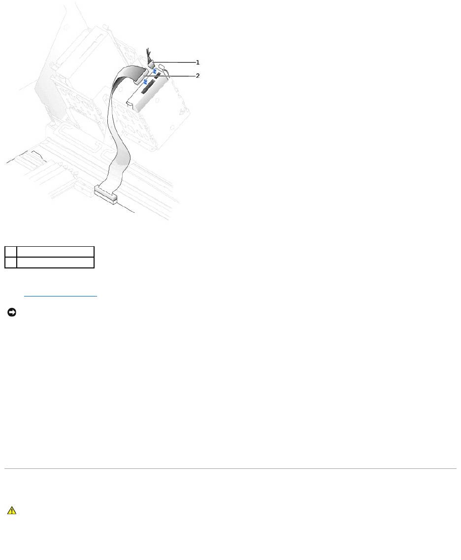
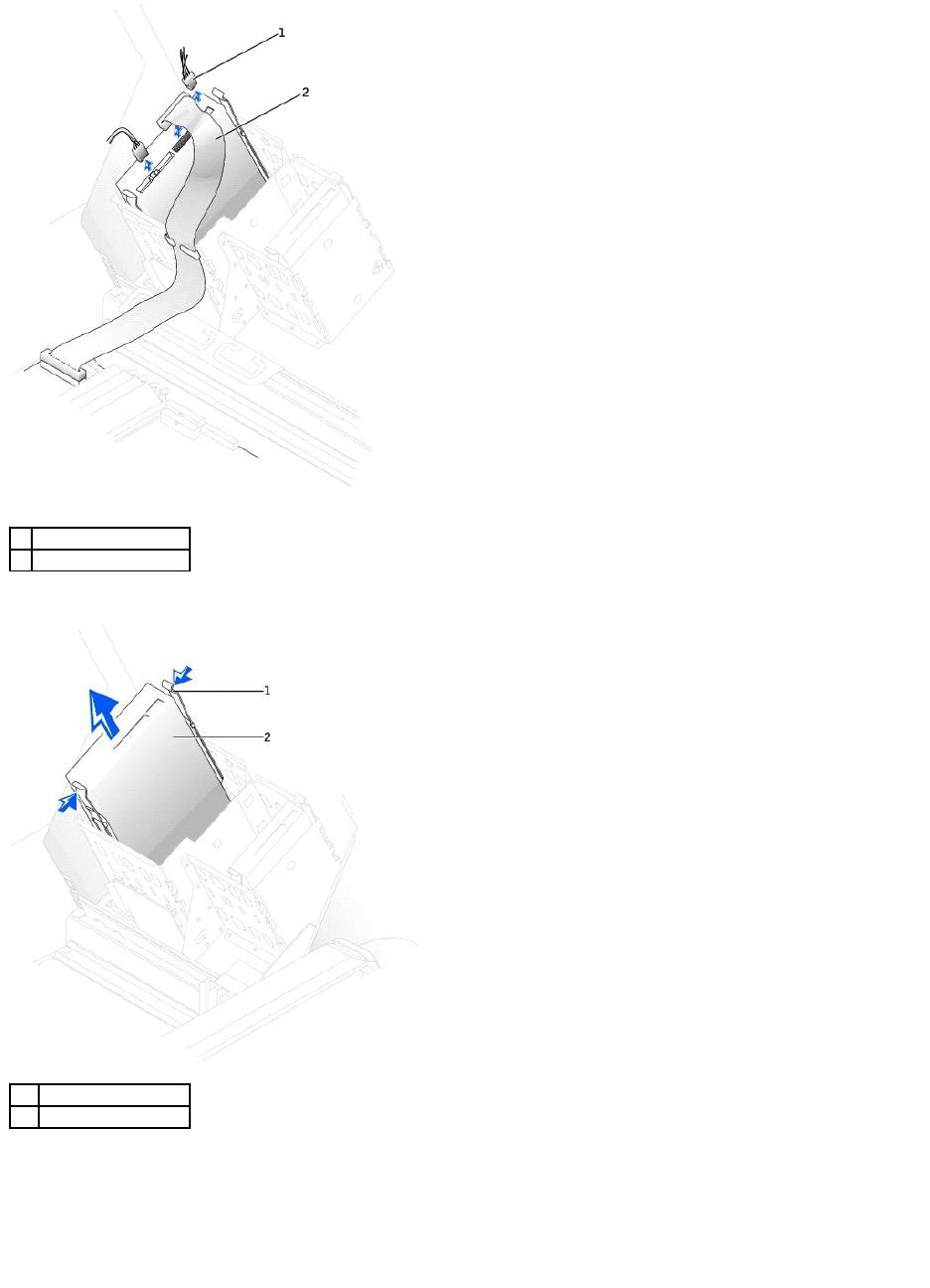
2. Disconnect the power and hard-drive cables from the drive.
NOTICE: Dell recommends that you use only SCSI cables purchased from Dell. Cables purchased elsewhere are not guaranteed to work with Dell
computers.
NOTICE: Dell recommends that you use only SCSI cables purchased from Dell. Cables purchased elsewhere are not guaranteed to work with Dell
computers.
CAUTION: Before you begin any of the procedures in this section, follow the safety instructions in the System Information Guide.
NOTICE: To avoid damage to the drive, do not set it on a hard surface. Instead, set the drive on a surface, such as a foam pad, that will sufficiently
cushion it.
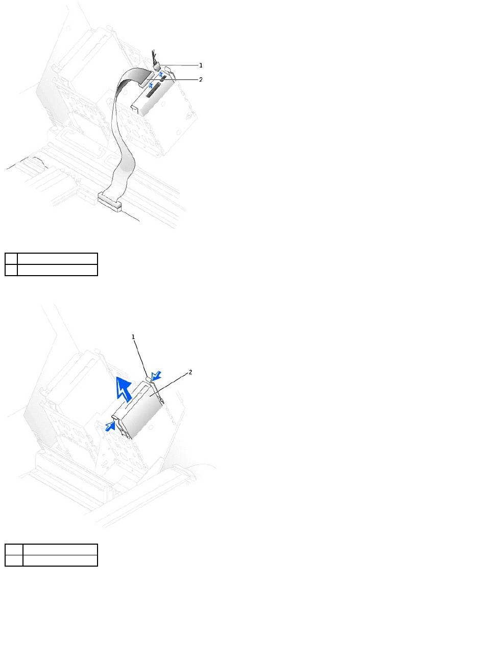
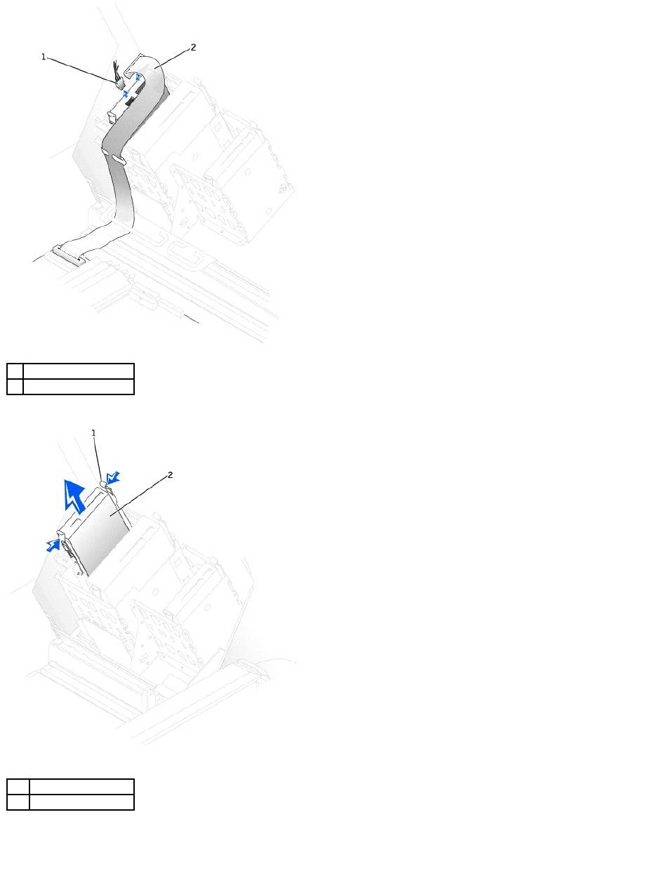
3. Press in on the tabs on each side of the drive and slide the drive up and out.
Installing a Hard Drive
1. Unpack the replacement hard drive, and prepare it for installation.
2. Check the documentation for the drive to verify that it is configured for your computer.
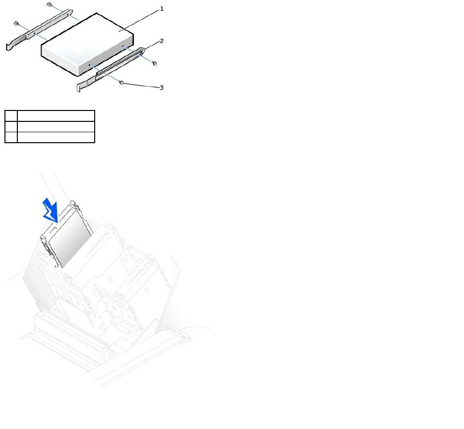
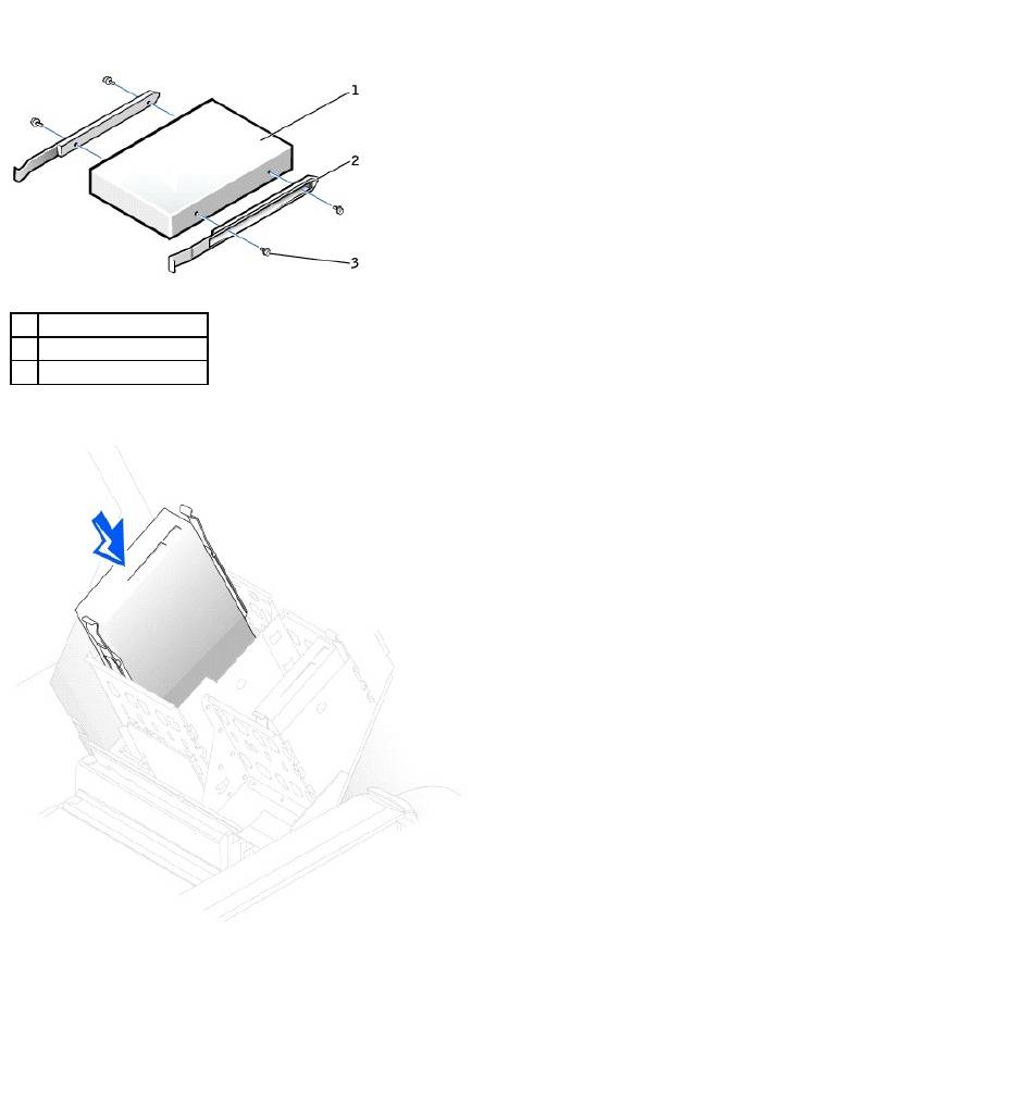
3. If your replacement hard drive does not have the bracket rails attached, remove the rails from the old drive by removing the two screws that secure
each rail to the drive. Attach the bracket rails to the new drive by aligning the screw holes on the drive with the screw holes on the bracket rails and
then inserting and tightening all four screws (two screws on each rail).
1
power cable
2
hard-drive cable
1
tabs (2)
2
hard drive
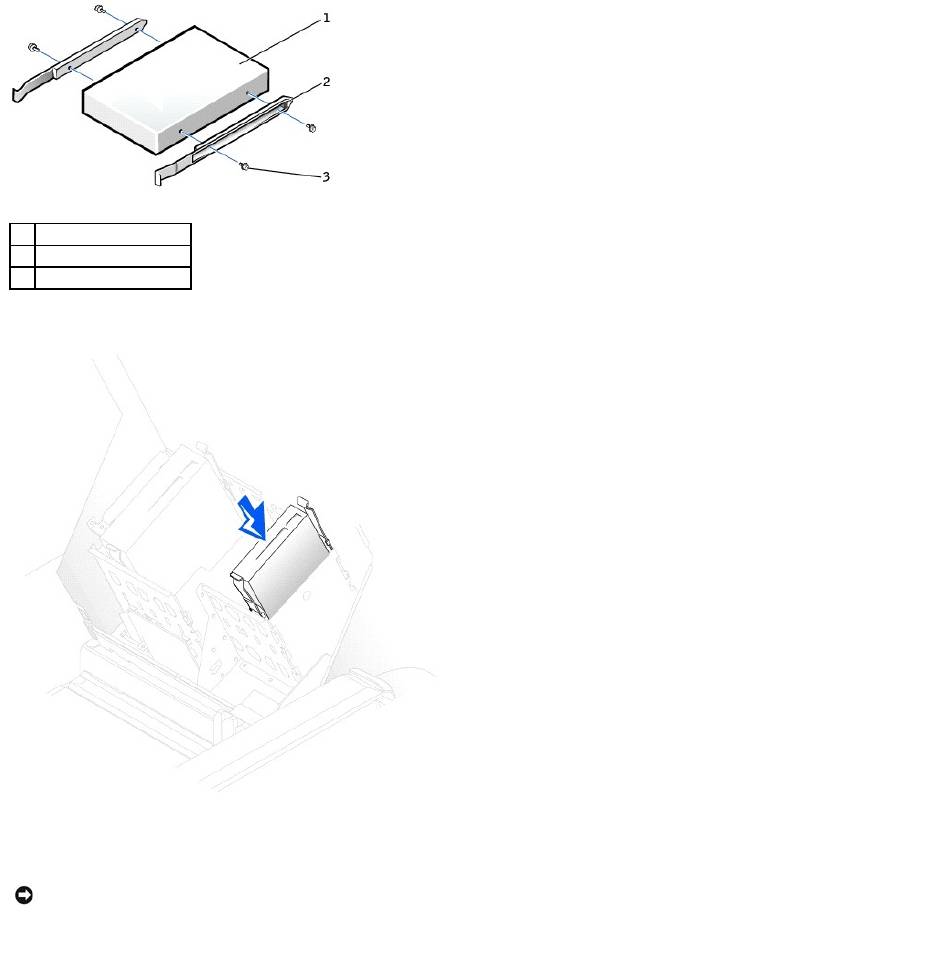
4. Gently slide the drive into place until the tabs securely click into position.
5. If you are installing a drive that has its own controller card, install the controller card in an expansion slot.
See the documentation that accompanied the drive and controller card to verify that the configuration is correct for your computer.
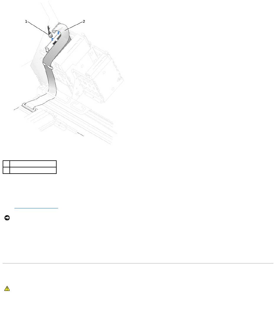
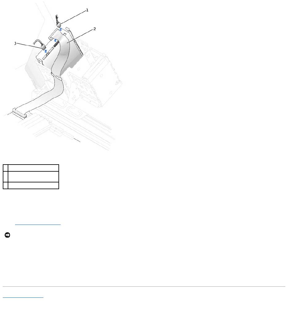
6. Connect the power and hard-drive cables to the drive.
1
drive
2
bracket rails (2)
3
screws (4)
NOTICE: Match the colored strip on the cable with pin 1 on the drive (pin 1 is marked as "1").
7. Check all connectors to be certain that they are properly cabled and firmly seated.
8. Close the computer cover.
9. Connect your computer and devices to electrical outlets, and turn them on.
See the documentation that came with the drive for instructions on installing any software required for drive operation.
10. If the drive you just installed is the primary drive, insert a bootable floppy disk into drive A.
11. Turn on the computer.
12. Enter system setup, and update the your drive configuration.
13. After you have updated the system settings, exit system setup, and restart the computer.
14. Partition and logically format your drive before you proceed to the next step.
See the documentation for your operating system for instructions.
15. Test the hard drive by running the Dell Diagnostics.
16. If the drive you just installed is the primary drive, install your operating system on the hard drive.
Floppy Drive
Removing a Floppy Drive
1. Disconnect the power and floppy-drive cables from the back of the floppy drive.
1
power cable
2
hard-drive cable
NOTICE: To connect a network cable, first plug the cable into the network wall jack and then plug it into the computer.
CAUTION: Before you begin any of the procedures in this section, follow the safety instructions in the System Information Guide.
2. Press inward on the two tabs on the sides of the drive, slide the drive upward, and remove it from the floppy-drive bay.
Installing a Floppy Drive
1. If you are replacing a drive and the the new drive does not have the bracket rails attached, remove the rails from the old drive by removing the two
screws that secure each rail to the drive. Attach the bracket to the new drive by aligning the screw holes on the drive with the screw holes on the
bracket rails and then inserting and tightening all four screws (two screws on each rail).
1
power cable
2
floppy-drive cable
1
tab (2)
2
floppy drive
2. Gently slide the drive into place until the tabs securely click into position.
3. Attach the power and floppy-drive cables to the floppy drive.
1
drive
2
bracket rails (2)
3
screws (4)
4. If you are installing a new floppy drive rather than replacing a drive, remove the front-panel inserts.
From inside the drive bay, gently press on each side of the insert until it pops out.
5. Check all cable connections, and fold cables out of the way to provide airflow for the fan and cooling vents.
6. Close the computer cover.
7. Connect your computer and devices to electrical outlets, and turn them on.
See the documentation that came with the drive for instructions on installing any software required for drive operation.
8. Enter system setup and update the appropriate Diskette Drive A option to reflect the size and capacity of your new floppy drive.
9. To verify that your computer works correctly, run the Dell Diagnostics.
CD/DVD Drive
Removing a CD/DVD Drive
1. Disconnect the power and CD/DVD drive cables from the back of the drive.
1
power cable
2
floppy-drive cable
NOTICE: To connect a network cable, first plug the cable into the network wall jack and then plug it into the computer.
CAUTION: Before you begin any of the procedures in this section, follow the safety instructions in the System Information Guide.
2. Press inward on the two tabs on the sides of the drive, and then slide the drive upward and remove it from the drive bay.
Installing a CD/DVD Drive
1. If you are installing a new drive, unpack the drive and prepare it for installation.
Check the documentation that accompanied the drive to verify that the drive is configured for your computer. If you are installing an IDE drive, configure
the drive for the cable select setting.
2. Connect the new drive to the set of rails that are attached to the inside of the cover. If a set of rails is not attached inside the computer cover, contact
Dell.
1
power cable
2
CD/DVD drive cable
1
tab (2)
2
CD/DVD drive
3. If you are installing a replacement drive and the new drive does not have the bracket rails attached, remove the rails from the old drive by removing
the two screws that secure each rail to the drive. Attach the bracket to the new drive by aligning the screw holes on the drive with the screw holes on
the bracket rails and then inserting and tightening all four screws (two screws on each rail).
4. Gently slide the drive into place until the tabs securely click into position.
5. If you are installing a drive that has its own controller card, install the controller card in an expansion slot.
See the documentation that accompanied the drive and controller card to verify that the configuration is correct for your computer.
6. Connect the power and CD/DVD drive cables to the drive.
If you are adding a drive that has an audio cable, connect the audio cable to the audio connector on the system board.
1
drive
2
bracket rails (2)
3
screws (4)
7. If you are installing a new CD/DVD drive rather than replacing a drive, remove the front-panel inserts.
From inside the drive bay, gently press on each side of the insert until it pops out.
8. Check all cable connections, and fold cables out of the way to provide airflow for the fan and cooling vents.
9. Close the computer cover.
10. Connect your computer and devices to electrical outlets, and turn them on.
See the documentation that came with the drive for instructions on installing any software required for drive operation.
11. Update your configuration information by setting the appropriate Drive option (0 or 1) under Drives: Secondary to Auto. See "Advanced Features" in
your User's Guide for more information.
12. Verify that your computer works correctly by running the Dell Diagnostics.
Back to Contents Page
1
power cable
2
audio cable (some drives
do not have this cable)
3
CD/DVD drive cable
NOTICE: To connect a network cable, first plug the cable into the network wall jack and then plug it into the computer.
Оглавление
- DellPrecision™Workstation650andDellPrecisionWorkstation450 Service Manual
- Battery
- Before You Begin
- Cards
- Chassis Intrusion Switch
- Control Panel
- Inside Your Computer — DellPrecision™450Computer
- Drives — DellPrecision™450Computer
- Power Supply — DellPrecision™450Computer
- Drive Door — DellPrecision™650Computer
- Microprocessor Airflow Shroud — DellPrecision™450Computer
- Card Fan and Guide — Dell Precision 650 Computer
- Front Panel
- I/O Panel
- Inside Your Computer — DellPrecision™650Computer
- Closing the Computer Cover
- Opening the Computer Cover
- Microprocessor
- Drives — DellPrecision™650Computer
- VRM
- Memory
- Microprocessor Airflow Shroud — DellPrecision™650Computer
- Power Supply — DellPrecision™650Computer
- System Board
