Asus P5QL: 1.6 Central Processing Unit (CPU)
1.6 Central Processing Unit (CPU): Asus P5QL
1.6 Central Processing Unit (CPU)
®
This motherboard comes with a surface mount LGA775 socket designed for the Intel
®
®
Core™2 Extreme / Core™2 Quad / Core™2 Duo / Pentium
Dual-Core / Celeron
Dual-Core
®
/ Celeron
processors.
• Unplug all power cables before installing the CPU.
• Connect the chassis fan cable to the CHA_FAN connector to ensure system stability.
• Upon purchase of the motherboard, ensure that the PnP cap is on the socket and the
socket contacts are not bent. Contact your retailer immediately if the PnP cap is missing,
or if you see any damage to the PnP cap/socket contacts/motherboard components.
ASUS will shoulder the cost of repair only if the damage is shipment/transit-related.
• Keep the cap after installing the motherboard. ASUS will process Return Merchandise
Authorization (RMA) requests only if the motherboard comes with the cap on the
LGA775 socket.
• The product warranty does not cover damage to the socket contacts resulting from
incorrect CPU installation/removal, or misplacement/loss/incorrect removal of the PnP
cap.
®
®
The motherboard supports Intel
LGA775 processors with the Intel
Enhanced Intel
®
SpeedStep
Technology (EIST) and Hyper-Threading Technology.
1.6.1 Installing the CPU
To install a CPU:
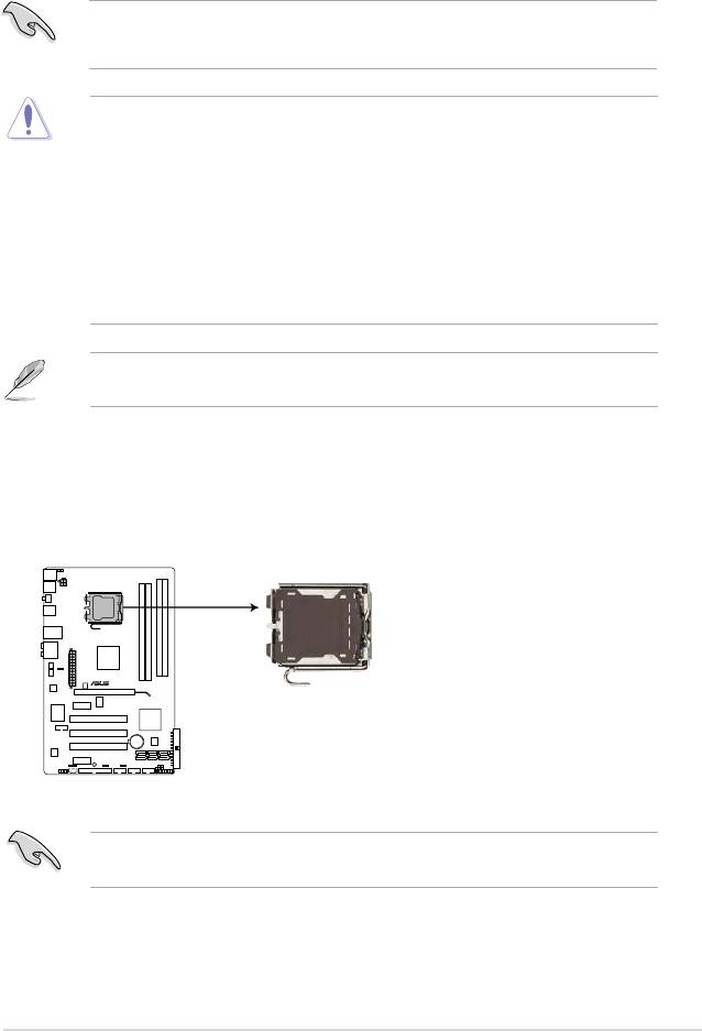
1. Locate the CPU socket on the motherboard.
Before installing the CPU, ensure that the cam box is facing towards you and the load lever
is on your left.
ASUS P5QL 1-7
P5QL
P5QL CPU Socket 775
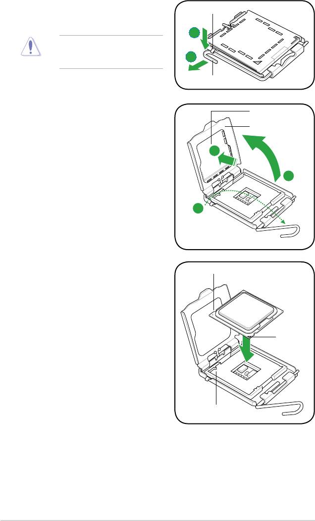
2. Press the load lever with your thumb
Retention tab
(A), then move it to the left (B) until it is
released from the retention tab.
A
To prevent damage to the socket
pins, do not remove the PnP cap
B
unless you are installing a CPU.
Load lever
3. Lift the load lever in the direction of the
PnP cap
arrow to a 135º angle.
Load plate
4B
4. Lift the load plate with your thumb and
forenger to a 100º angle (4A), then
push the PnP cap from the load plate
4A
window to remove (4B).
3
5. Position the CPU over the socket,
CPU notch
ensuring that the gold triangle is on the
bottom-left corner of the socket then t
the socket alignment key into the CPU
notch.
Gold
triangle
mark
Alignment key
1-8 Chapter 1: Product introduction
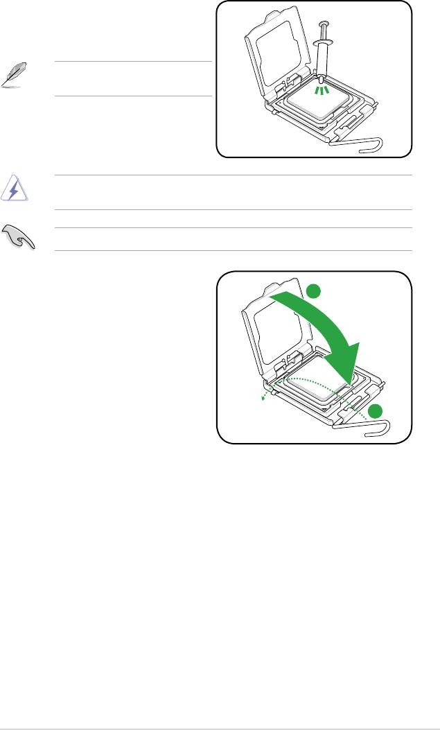
6. Apply some Thermal Interface Material
to the exposed area of the CPU that the
heatsink will be in contact with, ensuring
that it is spread in an even thin layer.
Some heatsinks come with pre-applied
thermal paste. If so, skip this step.
DO NOT eat the Thermal Interface Material. If it gets into your eyes or touches your skin,
ensure that you wash it off immediately, and seek professional medical help.
To prevent contaminating the paste, DO NOT spread the paste with your nger directly.
7. Close the load plate (A), then push
the load lever (B) until it snaps into the
A
retention tab.
B
ASUS P5QL 1-9
1.6.2 Installing the CPU heatsink and fan
®
The Intel
LGA775 processor requires a specially designed heatsink and fan assembly to
ensure optimum thermal condition and performance.
®
•
When you buy a boxed Intel
processor, the package includes the CPU fan and
®
heatsink assembly. If you buy a CPU separately, ensure that you use only Intel
-certied
multi-directional heatsink and fan.
• Ensure that you have installed the motherboard to the chassis before you install the
CPU fan and heatsink assembly.
• If you purchased a separate CPU heatsink and fan assembly, ensure that you have
properly applied Thermal Interface Material to the CPU heatsink or CPU before you
install the heatsink and fan assembly.
®
Your Intel
LGA775 heatsink and fan assembly comes in a push-pin design and requires no
tool to install.
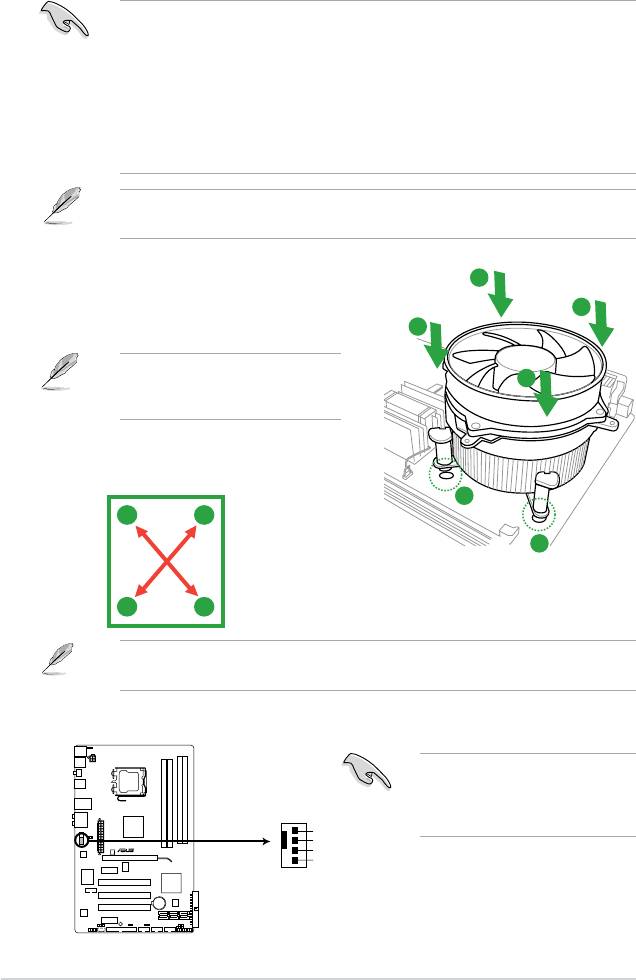
To install the CPU heatsink and fan:
A
1. Place the heatsink on top of the installed
B
CPU, ensuring that the four fasteners match
B
the holes on the motherboard.
Orient the heatsink and fan assembly
A
such that the CPU fan cable is closest
to the CPU fan connector.
2. Push down two fasteners at a time in a
diagonal sequence to secure the heatsink
and fan assembly in place.
1
A
B
1
B
A
The type of CPU heatsink and fan assembly may differ, but the installation steps and
functions should remain the same. The illustration above is for reference only.
3. Connect the CPU fan cable to the connector on the motherboard labeled CPU_FAN.
Do not forget to connect the CPU
fan connector! Hardware monitoring
errors can occur if you fail to plug this
connector.
1-10 Chapter 1: Product introduction
CPU_FAN
GND
CPU FAN PWR
P5QL
CPU FAN IN
CPU FAN PWM
P5QL CPU fan connector
Оглавление
- Contents
- Contents
- Contents
- Notices
- Safety information
- P5QL specications summary
- 1.1 Welcome!
- 1.4 Before you proceed
- 1.5 Motherboard overview
- 1.6 Central Processing Unit (CPU)
- 1.7 System memory
- 1.8 Expansion slots
- 1.9 Jumpers
- 1.10 Connectors
- 1.11 Software support
- 2.1 Managing and updating your BIOS
- 2.2 BIOS setup program
- 2.3 Main menu
- 2.4 Ai Tweaker menu
- 2.5 Advanced menu
- 2.6 Power menu
- 2.7 Boot menu
- 2.8 Tools menu
- 2.9 Exit menu
