Asus P5QL: 1.9 Jumpers
1.9 Jumpers: Asus P5QL
1.9 Jumpers
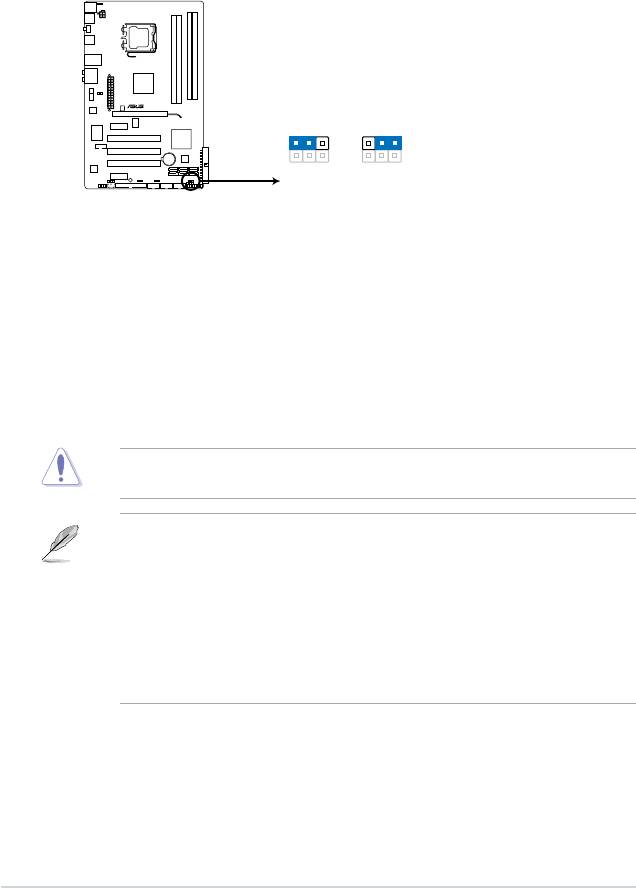
1. Clear RTC RAM (3-pin CLRTC)
This jumper allows you to clear the Real Time Clock (RTC) RAM in CMOS. You can
clear the CMOS memory of date, time, and system setup parameters by erasing
the CMOS RTC RAM data. The onboard button cell battery powers the RAM data in
CMOS, which include system setup information such as system passwords.
To erase the RTC RAM:
1. Turn OFF the computer and unplug the power cord.
2. Move the jumper cap from pins 1-2 (default) to pins 2-3. Keep the cap on pins 2-3
for about 5-10 seconds, then move the cap back to pins 1-2.
3. Plug the power cord and turn ON the computer.
4. Hold down the
<Del> key during the boot process and enter BIOS setup to re-enter
data.
Except when clearing the RTC RAM, never remove the cap on CLRTC jumper default
position. Removing the cap will cause system boot failure!
1-18 Chapter 1: Product introduction
P5QL
CLRTC
1 2 2 3
Normal
Clear RTC
(Default)
P5QL Clear RTC RAM
• If the steps above do not help, remove the onboard battery and move the jumper again
to clear the CMOS RTC RAM data. After clearing the CMOS, reinstall the battery.
• You do not need to clear the RTC when the system hangs due to overclocking. For
system failure due to overclocking, use the CPU Parameter Recall (C.P.R.) feature. Shut
down and reboot the system, then the BIOS automatically resets parameter settings to
default values.
• Due to the chipset limitation, AC power off is required before you use the C.P.R.
function. You must turn off and on the power supply or unplug and plug the power cord
before rebooting the system.
ASUS P5QL 1-19
PS2_USBPW56
21
2 3
+5V
+5VSB
(Default)
P5QL
P5QL Keyboard/Mouse power
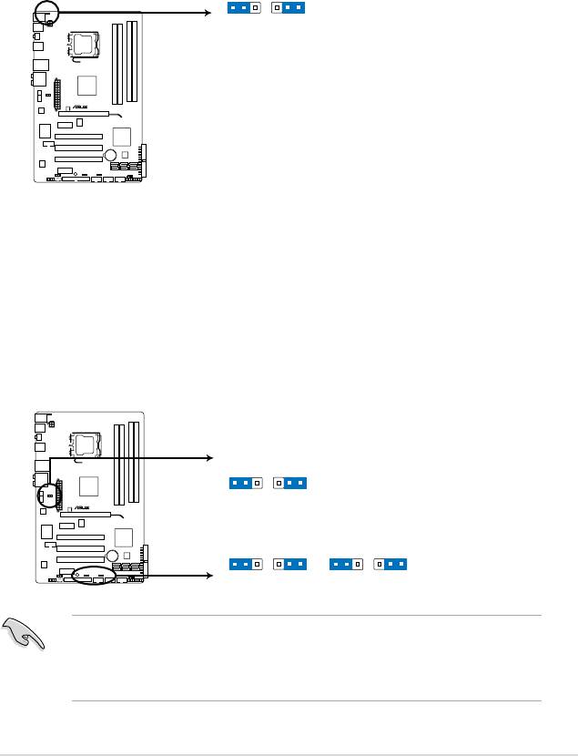
2. Keyboard/mouse power (3-pin PS2_USBPW56)
This jumper allows you to enable or disable the keyboard/mouse and USB port 5-6
wake-up feature. When you set this jumper to pins 2-3 (+5VSB), you can wake up the
computer by pressing a key on the keyboard (the default is the Space Bar), clicking
the mouse, or using a USB device. This feature requires an ATX power supply that can
supply at least 1A on the +5VSB lead, and a corresponding setting in the BIOS. The
USBPW56 jumper is for the rear USB ports.
USBPW1-4
21
2 3
+5V
+5VSB
P5QL
(Default)
USBPW1112 USBPW7-10
21
2 3
21
2 3
+5V
+5VSB
+5V
+5VSB
(Default)
(Default)
P5QL USB Device Wake Up
3. USB device wake-up (3-pin USBPW1-4, USBPW7-10, USBPW1112)
Set these jumpers to +5V to wake up the computer from S1 sleep mode (CPU stopped,
DRAM refreshed, system running in low power mode) using the connected USB
devices. Set to +5VSB to wake up from S3 and S4 sleep modes (no power to CPU,
DRAM in slow refresh, power supply in reduced power mode).
The USBPW1-4 and PS2_USBPW56 jumpers are for the rear USB ports. The
USBPW7-10 and USB1112 jumpers are for the internal USB connectors that you can
connect to additional USB ports.
• The USB device wake-up feature requires a power supply that can provide 500mA on
the +5VSB lead for each USB port; otherwise, the system would not power up.
• The total current consumed must NOT exceed the power supply capability (+5VSB)
whether under normal condition or in sleep mode.
Оглавление
- Contents
- Contents
- Contents
- Notices
- Safety information
- P5QL specications summary
- 1.1 Welcome!
- 1.4 Before you proceed
- 1.5 Motherboard overview
- 1.6 Central Processing Unit (CPU)
- 1.7 System memory
- 1.8 Expansion slots
- 1.9 Jumpers
- 1.10 Connectors
- 1.11 Software support
- 2.1 Managing and updating your BIOS
- 2.2 BIOS setup program
- 2.3 Main menu
- 2.4 Ai Tweaker menu
- 2.5 Advanced menu
- 2.6 Power menu
- 2.7 Boot menu
- 2.8 Tools menu
- 2.9 Exit menu
