Asus P5QL: 1.5 Motherboard overview
1.5 Motherboard overview: Asus P5QL
1.5 Motherboard overview
Before you install the motherboard, study the conguration of your chassis to ensure that the
motherboard ts into it.
Ensure that you unplug the power cord before installing or removing the motherboard.
Failure to do so can cause you physical injury and damage motherboard components.
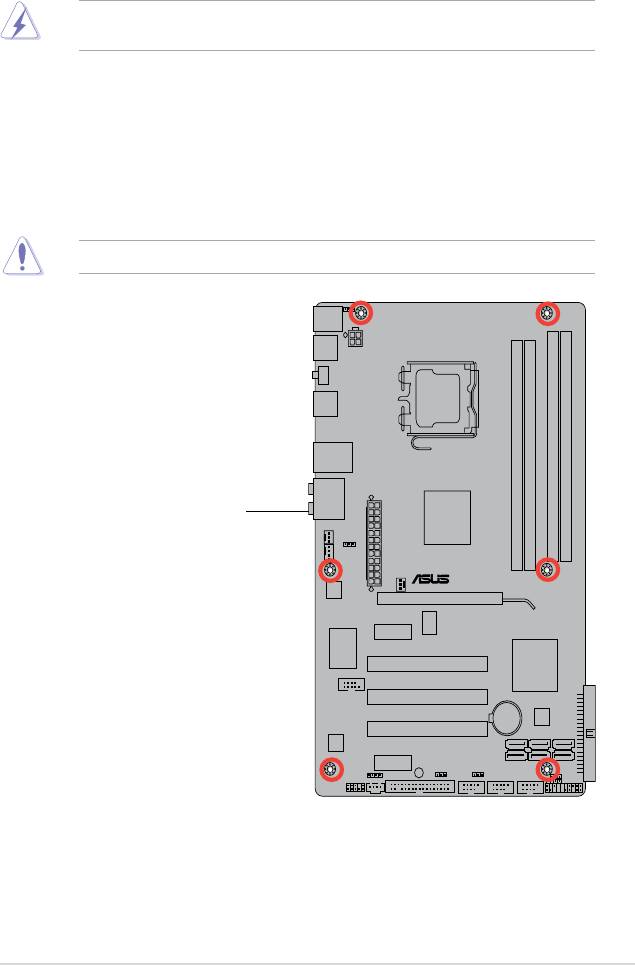
1.5.1 Placement direction
When installing the motherboard, ensure that you place it into the chassis in the correct
orientation. The edge with external ports goes to the rear part of the chassis as indicated in
the image below.
1.5.2 Screw holes
Place six screws into the holes indicated by circles to secure the motherboard to the chassis.
Do not overtighten the screws! Doing so can damage the motherboard.
ASUS P5QL 1-5
P5QL
Place this side towards
the rear of the chassis
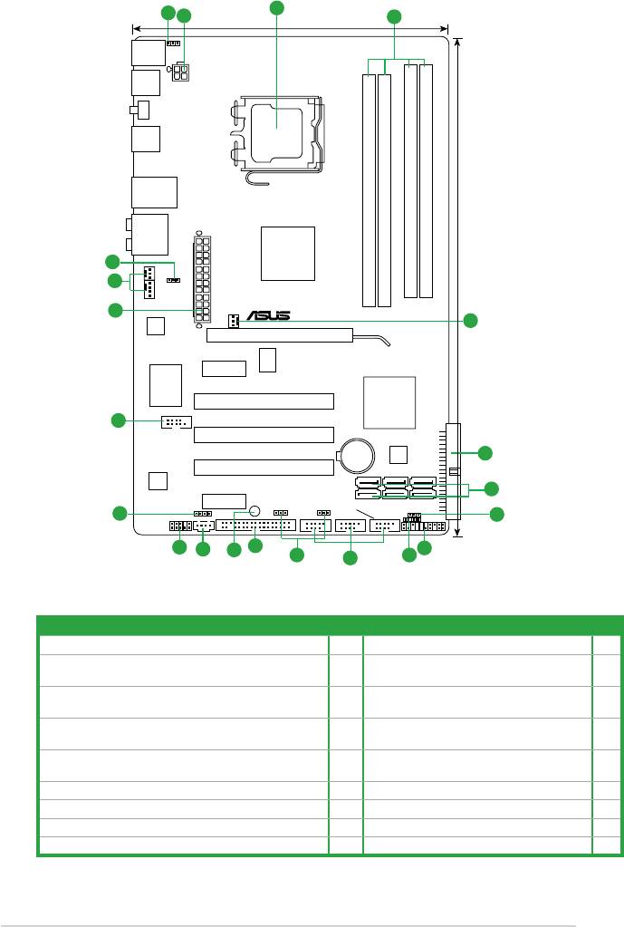
1.5.3 Motherboard layout
1.5.4 Layout contents
1-6 Chapter 1: Product introduction
3
1
2
4
19.3cm(7.6in)
PS2_USBPW56
KBMS
USB56
ATX12V
SPDIF_O
USB34
LGA775
LAN1_USB12
AUDIO
DDR2 DIMM_B1 (64bit, 240-pin module)
DDR2 DIMM_B2 (64bit, 240-pin module)
Intel
®
DDR2 DIMM_A1 (64bit, 240-pin module)
DDR2 DIMM_A2 (64bit, 240-pin module)
12
CHA_FAN
P43
5
USBPW1-4
EATXPWR
CPU_FAN
2
PWR_FAN
30.5cm(12.0in)
P5QL
RTL
5
8111C
PCIEX16
RTM
PCIEX1_1
870T-954
Super
I/O
Intel
®
PCI1
ICH10
COM1
17
PCI2
PRI_IDE
Lithium Cell
8Mb
CMOS Power
BIOS
6
PCI3
VIA
VT1708S
7
PCIEX1_2
SB_PWR
SATA6 SATA4 SATA2
USBPW7-10USBPW1112
USB910
SATA5 SATA3 SATA1
SPDIF_OUT
CLRTC
16
FLOPPY
USB1112 USB78
CD
CHASSIS
PANEL
8
AAFP
15
13
14
18
9
12
11
10
Connectors/Jumpers/Slots/LED Page Connectors/Jumpers/Slots/LED
1. Keyboard/mouse power (3-pin PS2_USBPW56) 1-19 10. Chassis intrusion connector 1-24
2. ATX power connectors (24-pin EATXPWR, 4-pin ATX 12V)
1-26 11. USB connectors (10-1 pin USB78, USB910,
1-26
USB1112)
3. LGA775 CPU socket
1-7 12. USB device wake-up (3-pin USBPW1-4,
1-19
USBPW7-10, USBPW1112)
4. DDR2 DIMM slots
1-11 13. Floppy disk drive connector
1-21
(34-1 pin FLOPPY)
5. CPU, chassis, and power fan connectors
1-24 14. Optical drive audio connector (4-pin CD) 1-23
(4-pin CPU_FAN, 3-pin CHA_FAN, 3-pin PWR_FAN)
6. IDE connector (40-1 pin PRI_IDE)
1-23 15. Front panel audio connector (10-1 pin AAFP) 1-25
7. Serial ATA connectors (7-pin SATA1-6)
1-22 16. Digital audio connector (4-1 pin SPDIF_OUT) 1-22
8. Clear RTC RAM (3-pin CLRTC)
1-18 17. Serial port connector (10-1 pin COM1) 1-25
9. System panel connector (20-8 pin PANEL)
1-27 18. Onboard LED (SB_PWR) 1-4
Оглавление
- Contents
- Contents
- Contents
- Notices
- Safety information
- P5QL specications summary
- 1.1 Welcome!
- 1.4 Before you proceed
- 1.5 Motherboard overview
- 1.6 Central Processing Unit (CPU)
- 1.7 System memory
- 1.8 Expansion slots
- 1.9 Jumpers
- 1.10 Connectors
- 1.11 Software support
- 2.1 Managing and updating your BIOS
- 2.2 BIOS setup program
- 2.3 Main menu
- 2.4 Ai Tweaker menu
- 2.5 Advanced menu
- 2.6 Power menu
- 2.7 Boot menu
- 2.8 Tools menu
- 2.9 Exit menu
