Pioneer MVH-350BT: Connections Using an AUX source If an unwanted display appears System menu
Connections Using an AUX source If an unwanted display appears System menu: Pioneer MVH-350BT
Table of contents
- About this unit About this manual In case of trouble
- Head unit Display indication Set up menu
- Tuner Basic operations Frequently used menu operations
- Switching the display Function settings PTY list Using PTY functions
- USB storage device Switching the display Operations using special buttons iPod Basic operations Basic operations Selecting and playing files/ tracks from the name list Switching the display Function settings
- Operations using special buttons Browsing for a song Operating this unit’s iPod function from your iPod Function settings Playing songs related to the currently playing song
- Connection menu operation Using Bluetooth wireless technology Using Bluetooth telephone
- Phone menu operation
- Function and operation Function settings Switching the display Bluetooth Audio Setting up for Bluetooth audio Operations using special buttons Audio adjustments
- System menu
- Switching the dimmer setting
- Connections Using an AUX source If an unwanted display appears System menu
- Power cord Installation DIN front/rear mount DIN Front-mount
- Installing the microphone When installing the microphone on the sun visor When installing the microphone DIN Rear-mount on the steering column
- Troubleshooting Error messages Adjusting the microphone angle
- Message Cause Action USB storage device/iPod Bluetooth device
- Handling guidelines Compressed audio compatibility (USB) iPod compatibility
- Bluetooth profiles Russian character chart
- Specifications
3 Turn M.C. to change the menu option
— Never wire the negative speaker cable directly
The rear speaker leads output and the RCA output
Connections
and press to select SYSTEM.
to ground.
of this unit can be used to connect a full-range
Important
— Never band together negative cables of multi-
speaker or subwoofer. Select a suitable option for
4 Turn M.C. to select the system menu
! When installing this unit in a vehicle without
ple speakers.
your connection.
function.
an ACC (accessory) position on the ignition
! When this unit is on, control signals are sent
1 Press M.C. to display the setting mode.
Once selected, the following system menu func-
switch, failure to connect the red cable to the
through the blue/white cable. Connect this
2 Turn M.C. to select the desired setting.
tions can be adjusted.
terminal that detects operation of the ignition
cable to the system remote control of an ex-
You can select any one of the options in the fol-
For details, refer to System menu on page 11.
key may result in battery drain.
ternal power amp or the vehicle’s auto-anten-
lowing list:
na relay control terminal (max. 300 mA
! REAR/SUB.W – Select when there is a full-
Using an AUX source
F
O
range speaker connected to the rear speak-
N
12 V DC). If the vehicle is equipped with a
O
F
S
T
er leads output and there is a subwoofer
R
A
glass antenna, connect it to the antenna
1 Insert the stereo mini plug into the AUX
T
connected to the RCA output.
booster power supply terminal.
input jack.
! SUB.W/SUB.W – Select when there is a
! Never connect the blue/white cable to the
ACC position No ACC position
subwoofer connected directly to the rear
power terminal of an external power amp.
2 Press SRC/OFF to select AUX as the
speaker leads output without any auxiliary
! Use of this unit in conditions other than the
source.
Also, never connect it to the power terminal
amp and there is a subwoofer connected
following could result in fire or malfunction.
of the auto antenna. Doing so may result in
Note
to the RCA output.
— Vehicles with a 12-volt battery and negative
battery drain or a malfunction.
AUX cannot be selected unless the auxiliary set-
! REAR/REAR – Select when there is a full-
grounding.
! The black cable is ground. Ground cables for
ting is turned on. For more details, refer to AUX
range speaker connected to the rear speak-
— Speakers with 50 W (output value) and 4 W to
this unit and other equipment (especially,
(auxiliary input) on the previous page.
er leads output and the RCA output.
8 W (impedance value).
high-current products such as power amps)
If there is a full-range speaker connected to
! To prevent a short-circuit, overheating or mal-
must be wired separately. If they are not, an
the rear speaker leads output and the RCA
Switching the display
function, be sure to follow the directions
accidental detachment may result in a fire or
output is not used, you may select either
below.
malfunction.
REAR/SUB.W or REAR/REAR.
Selecting the desired text information
— Disconnect the negative terminal of the bat-
1 Press DISP to cycle between the following:
S/W UPDATE (updating the software)
tery before installation.
This unit
! Source name
— Secure the wiring with cable clamps or adhe-
This function is used to update this unit with the
! Source name and clock
sive tape. Wrap adhesive tape around wiring
3
latest Bluetooth software. For about Bluetooth
that comes into contact with metal parts to
software and updating, refer to our website.
protect the wiring.
1
2
! Never turn the unit off while the Bluetooth soft-
If an unwanted display appears
— Place all cables away from moving parts,
ware is being updated.
Turn off the unwanted display using the proce-
such as the shift lever and seat rails.
1 Press M.C. to display the data transfer mode.
dures listed below.
— Place all cables away from hot places, such
Follow the on-screen instructions to finish up-
as near the heater outlet.
dating the Bluetooth software.
1 Press M.C. to display the main menu.
— Do not connect the yellow cable to the battery
by passing it through the hole to the engine
2 Turn M.C. to change the menu option
compartment.
System menu
and press to select SYSTEM.
— Cover any disconnected cable connectors
1 Press and hold SRC/OFF until the unit
with insulating tape.
3 Turn M.C. to display DEMO OFF and press
turns off.
— Do not shorten any cables.
to select.
— Never cut the insulation of the power cable of
2 Press and hold SRC/OFF until the main
4 Turn M.C. to switch to YES.
this unit in order to share the power with
menu appears in the display.
other devices. The current capacity of the
5 Press M.C. to select.
cable is limited.
— Use a fuse of the rating prescribed.
6 78
Section
Operating this unit
Installation
02
03
English
4
5
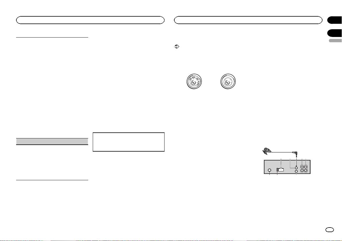
1 Power cord input
2 Microphone input (MVH-350BT only)
3 Microphone (MVH-350BT only)
4m
4 Rear output or subwoofer output
5 Front output
6 Antenna input
7 Fuse (10 A)
8 Wired remote input
En
13
