Pioneer DEH-2400UB EU: Installation
Installation: Pioneer DEH-2400UB EU
Table of contents
- About this unit About this manual Demo mode In case of trouble
- Head unit Display indication Set up menu
- Menu operations identical for set up menu/function settings/audio adjustments/ initial settings/lists Basic operations
- CD/CD-R/CD-RW and USB storage devices iPod
- Operating this unit’s iPod function from your iPod Playing songs related to the currently playing song Displaying text information Advanced operations using special buttons
- Function settings Audio adjustments
- Initial settings Selecting the illumination color Selecting the key color from the illumination color list
- Selecting key and display color from the illumination color list Switching the dimmer setting Selecting the display color from the illumination color list
- Connections This unit Power cord
- Installation
- Troubleshooting Error messages
- Handling guidelines
- Compressed audio compatibility (disc, USB)
- iPod compatibility Russian character chart Sequence of audio files Copyright and trademark
- Specifications
Section
03
Installation
Installation
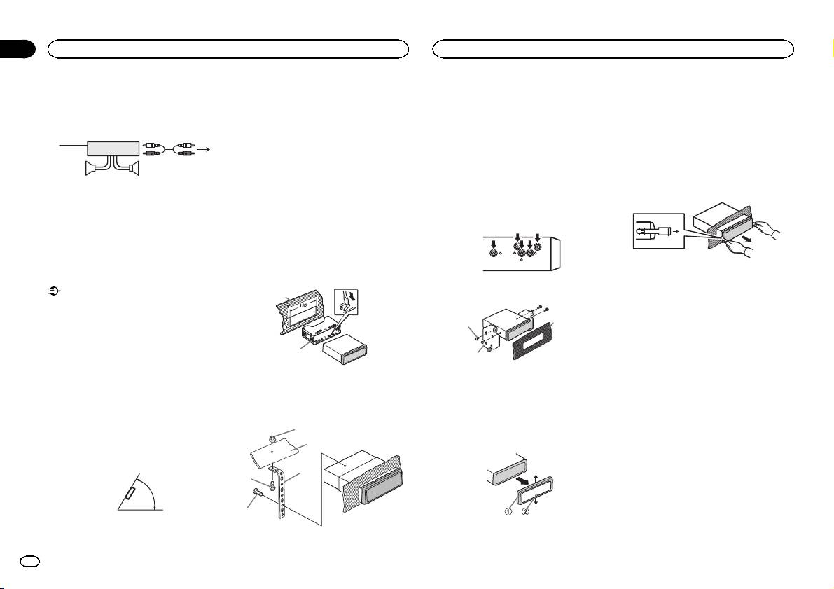
Power amp (sold separately)
DIN front/rear mount
2 Firewall or metal support
! Releasing the front panel allows easier ac-
3 Metal strap
cess to the trim ring.
Perform these connections when using the op-
This unit can be properly installed using either
4 Screw
! When reattaching the trim ring, point the
tional amplifier.
front-mount or rear-mount installation.
5 Screw (M4 × 8)
side with the notched tab down.
Use commercially available parts when instal-
3
# Make sure that the unit is installed securely in
1
ling.
2
place. An unstable installation may cause skipping
2 Insert the supplied extraction keys into
4
or other malfunctions.
both sides of the unit until they click into
DIN Front-mount
55
place.
1 Insert the mounting sleeve into the dash-
DIN Rear-mount
3 Pull the unit out of the dashboard.
1 System remote control
board.
1 Determine the appropriate position
Connect to Blue/white cable.
For installation in shallow spaces, use the sup-
where the holes on the bracket and the side
2 Power amp (sold separately)
plied mounting sleeve. If there is enough space,
of the unit match.
3 Connect with RCA cables (sold separately)
use the mounting sleeve that came with the ve-
4 To Rear output or subwoofer output
hicle.
5 Rear speaker or subwoofer
2 Secure the mounting sleeve by using a
screwdriver to bend the metal tabs (90°) into
Installation
place.
Removing and re-attaching the front
Important
2 Tighten two screws on each side.
panel
1
! Check all connections and systems before
You can remove the front panel to protect your
final installation.
unit from theft.
3
! Do not use unauthorized parts as this may
1
Press the detach button and push the front
cause malfunctions.
panel upward and pull it toward you.
! Consult your dealer if installation requires
For details, refer to Removing the front panel to
2
drilling of holes or other modifications to the
2
protect your unit from theft and Re-attaching the
vehicle.
front panel on page 4.
! Do not install this unit where:
1 Dashboard
1 Tapping screw (5 mm × 8 mm)
— it may interfere with operation of the vehicle.
2 Mounting sleeve
2 Mounting bracket
— it may cause injury to a passenger as a result
3 Dashboard or console
of a sudden stop.
3 Install the unit as illustrated.
! The semiconductor laser will be damaged if
Removing the unit
it overheats. Install this unit away from hot
1
places such as near the heater outlet.
1 Remove the trim ring.
2
! Optimum performance is obtained when the
unit is installed at an angle of less than 60°.
3
4
60°
5
1 Trim ring
1 Nut
2 Notched tab
12
En
