Pioneer DEH-2400UB EU: Connections This unit Power cord
Connections This unit Power cord: Pioneer DEH-2400UB EU
Table of contents
- About this unit About this manual Demo mode In case of trouble
- Head unit Display indication Set up menu
- Menu operations identical for set up menu/function settings/audio adjustments/ initial settings/lists Basic operations
- CD/CD-R/CD-RW and USB storage devices iPod
- Operating this unit’s iPod function from your iPod Playing songs related to the currently playing song Displaying text information Advanced operations using special buttons
- Function settings Audio adjustments
- Initial settings Selecting the illumination color Selecting the key color from the illumination color list
- Selecting key and display color from the illumination color list Switching the dimmer setting Selecting the display color from the illumination color list
- Connections This unit Power cord
- Installation
- Troubleshooting Error messages
- Handling guidelines
- Compressed audio compatibility (disc, USB)
- iPod compatibility Russian character chart Sequence of audio files Copyright and trademark
- Specifications
— Never wire the negative speaker cable directly
Connections
to ground.
Important
— Never band together negative cables of multi-
! When installing this unit in a vehicle without
ple speakers.
an ACC (accessory) position on the ignition
! When this unit is on, control signals are sent
switch, failure to connect the red cable to the
through the blue/white cable. Connect this
terminal that detects operation of the ignition
cable to the system remote control of an ex-
key may result in battery drain.
ternal power amp or the vehicle’s auto-anten-
na relay control terminal (max. 300 mA
O
F
F
N
12 V DC). If the vehicle is equipped with a
O
S
T
A
glass antenna, connect it to the antenna
T
R
booster power supply terminal.
! Never connect the blue/white cable to the
ACC position No ACC position
power terminal of an external power amp.
! Use of this unit in conditions other than the
Also, never connect it to the power terminal
following could result in fire or malfunction.
of the auto antenna. Doing so may result in
— Vehicles with a 12-volt battery and negative
battery drain or a malfunction.
grounding.
! The black cable is ground. Ground cables for
— Speakers with 50 W (output value) and 4 ohm
this unit and other equipment (especially,
to 8 ohm (impedance value).
high-current products such as power amps)
! To prevent a short-circuit, overheating or mal-
must be wired separately. If they are not, an
function, be sure to follow the directions
accidental detachment may result in a fire or
below.
malfunction.
— Disconnect the negative terminal of the bat-
tery before installation.
This unit
— Secure the wiring with cable clamps or adhe-
sive tape. Wrap adhesive tape around wiring
1
that comes into contact with metal parts to
protect the wiring.
— Place all cables away from moving parts,
such as the shift lever and seat rails.
— Place all cables away from hot places, such
as near the heater outlet.
— Do not connect the yellow cable to the battery
by passing it through the hole to the engine
compartment.
— Cover any disconnected cable connectors
with insulating tape.
— Do not shorten any cables.
— Never cut the insulation of the power cable of
this unit in order to share the power with
other devices. The current capacity of the
cable is limited.
— Use a fuse of the rating prescribed.
3 45
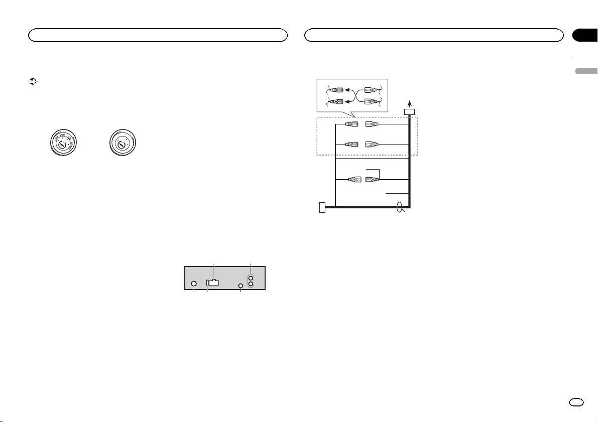
Power cord
3
4
1
2
5
6
3
4
7
5
6
8
a
9
b
e
2
1 Power cord input
2 Rear output or subwoofer output
3 Antenna input
4 Fuse (10 A)
5 Wired remote input
Hard-wired remote control adaptor can be
connected (sold separately).
d
Section
Installation
Installation
03
9 Blue/white
The pin position of the ISO connector will dif-
English
fer depending on the type of vehicle. Connect
9 and b when Pin 5 is an antenna control
type. In another type of vehicle, never con-
nect 9 and b.
a Blue/white
Connect to system control terminal of the
power amp (max. 300 mA 12 V DC).
b Blue/white
Connect to auto-antenna relay control termi-
nal (max. 300 mA 12 V DC).
c Yellow/black
If you use an equipment with Mute function,
wire this lead to the Audio Mute lead on that
equipment. If not, keep the Audio Mute lead
free of any connections.
d Speaker leads
c
White: Front left +
White/black: Front left *
Gray: Front right +
1 To power cord input
Gray/black: Front right *
2 Depending on the kind of vehicle, the func-
Green: Rear left + or subwoofer +
tion of 3 and 5 may be different. In this
Green/black: Rear left * or subwoofer *
case, be sure to connect 4 to 5 and 6 to
Violet: Rear right + or subwoofer +
3.
Violet/black: Rear right * or subwoofer *
3 Yellow
e ISO connector
Back-up (or accessory)
In some vehicles, the ISO connector may be
4 Yellow
divided into two. In this case, be sure to con-
Connect to the constant 12 V supply termi-
nect to both connectors.
nal.
Notes
5 Red
! Change the initial setting of this unit. Refer
Accessory (or back-up)
to REAR-SP (rear output setting) on page 9.
6 Red
Refer to PREOUT (preout setting) on page 9.
Connect to terminal controlled by ignition
The subwoofer output of this unit is monau-
switch (12 V DC).
ral.
7 Connect leads of the same color to each
! When using a subwoofer of 70 W (2 Ω), be
other.
sure to connect the subwoofer to the violet
8 Black (chassis ground)
and violet/black leads of this unit. Do not
connect anything to the green and green/
black leads.
En
11
