Pioneer DEH-150MP: Installation DIN front/rear mount
Installation DIN front/rear mount: Pioneer DEH-150MP
Table of contents
- About this unit Head unit In case of trouble Display indication Set up menu
- Frequently used menu operations Basic operations
- Tuner
- Audio adjustments CD/CD-R/CD-RW
- System menu
- Switching the dimmer setting System menu Initial menu
- Connections Using an AUX source
- Installation DIN front/rear mount
- Troubleshooting Error messages
- Handling guidelines Compressed audio compatibility
- Specifications Russian character chart Copyright and trademark Sequence of audio files
Power cord
3
4
1
2
5
6
3
4
7
5
6
8
a
9
b
e
d
9 Blue/white
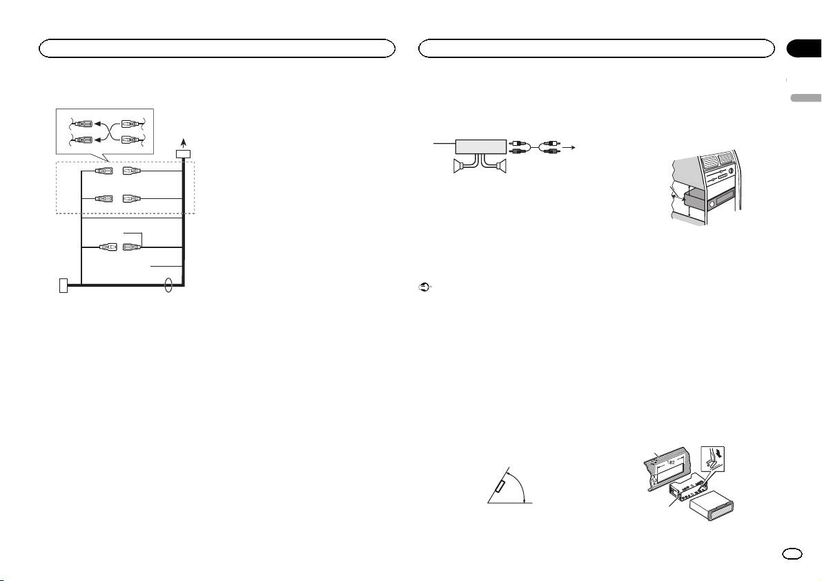
Power amp (sold separately)
! When installing, to ensure proper heat dis-
The pin position of the ISO connector will dif-
persal when using this unit, make sure you
Perform these connections when using the op-
fer depending on the type of vehicle. Connect
leave ample space behind the rear panel and
tional amplifier.
9 and b when Pin 5 is an antenna control
wrap any loose cables so they are not block-
type. In another type of vehicle, never con-
3
ing the vents.
1
nect 9 and b.
2
a Blue/white
4
Connect to system control terminal of the
55
power amp (max. 300 mA 12 V DC).
b Blue/white
1 System remote control
Connect to auto-antenna relay control termi-
Connect to Blue/white cable.
nal (max. 300 mA 12 V DC).
2 Power amp (sold separately)
c Yellow/black
3 Connect with RCA cables (sold separately)
If you use an equipment with Mute function,
4 To Rear output or subwoofer output
wire this lead to the Audio Mute lead on that
5 Rear speaker or subwoofer
equipment. If not, keep the Audio Mute lead
free of any connections.
d Speaker leads
c
Installation
White: Front left +
Important
White/black: Front left *
Gray: Front right +
! Check all connections and systems before
1 To power cord input
Gray/black: Front right *
final installation.
2 Depending on the kind of vehicle, the func-
Green: Rear left + or subwoofer +
! Do not use unauthorized parts as this may
tion of 3 and 5 may be different. In this
Green/black: Rear left * or subwoofer *
cause malfunctions.
case, be sure to connect 4 to 5 and 6 to
Violet: Rear right + or subwoofer +
! Consult your dealer if installation requires
3.
Violet/black: Rear right * or subwoofer *
drilling of holes or other modifications to the
3 Yellow
e ISO connector
vehicle.
Back-up (or accessory)
In some vehicles, the ISO connector may be
! Do not install this unit where:
4 Yellow
divided into two. In this case, be sure to con-
— it may interfere with operation of the vehicle.
Connect to the constant 12 V supply termi-
nect to both connectors.
— it may cause injury to a passenger as a result
nal.
of a sudden stop.
Notes
5 Red
! The semiconductor laser will be damaged if
! Change the initial menu of this unit. Refer to
Accessory (or back-up)
it overheats. Install this unit away from hot
SP-P/O MODE (rear output and preout set-
6 Red
places such as near the heater outlet.
ting) on page 7.
Connect to terminal controlled by ignition
! Optimum performance is obtained when the
The subwoofer output of this unit is monau-
switch (12 V DC).
unit is installed at an angle of less than 60°.
ral.
7 Connect leads of the same color to each
! When using a subwoofer of 70 W (2 W), be
other.
60°
sure to connect the subwoofer to the violet
8 Black (chassis ground)
and violet/black leads of this unit. Do not
connect anything to the green and green/
black leads.
5cmcm
Section
Installation
Installation
03
English
Leave ample
5 cm
space
5 cm
DIN front/rear mount
This unit can be properly installed using either
front-mount or rear-mount installation.
Use commercially available parts when instal-
ling.
DIN Front-mount
1 Insert the mounting sleeve into the dash-
board.
For installation in shallow spaces, use the sup-
plied mounting sleeve. If there is enough space,
use the mounting sleeve that came with the ve-
hicle.
2 Secure the mounting sleeve by using a
screwdriver to bend the metal tabs (90°) into
place.
1
2
1 Dashboard
En
9
