Pioneer DEH-150MP: Connections Using an AUX source
Connections Using an AUX source: Pioneer DEH-150MP
Table of contents
- About this unit Head unit In case of trouble Display indication Set up menu
- Frequently used menu operations Basic operations
- Tuner
- Audio adjustments CD/CD-R/CD-RW
- System menu
- Switching the dimmer setting System menu Initial menu
- Connections Using an AUX source
- Installation DIN front/rear mount
- Troubleshooting Error messages
- Handling guidelines Compressed audio compatibility
- Specifications Russian character chart Copyright and trademark Sequence of audio files
For details, refer to System menu on page 6.
— Never wire the negative speaker cable directly
Connections
to ground.
Important
— Never band together negative cables of multi-
Using an AUX source
! When installing this unit in a vehicle without
ple speakers.
an ACC (accessory) position on the ignition
! When this unit is on, control signals are sent
1 Insert the stereo mini plug into the AUX
switch, failure to connect the red cable to the
through the blue/white cable. Connect this
input jack.
terminal that detects operation of the ignition
cable to the system remote control of an ex-
key may result in battery drain.
ternal power amp or the vehicle’s auto-anten-
2 Press SRC/OFF to select AUX as the
na relay control terminal (max. 300 mA
source.
F
F
O
N
12 V DC). If the vehicle is equipped with a
O
S
Note
T
A
glass antenna, connect it to the antenna
T
R
AUX cannot be selected unless the auxiliary set-
booster power supply terminal.
ting is turned on. For more details, refer to AUX
! Never connect the blue/white cable to the
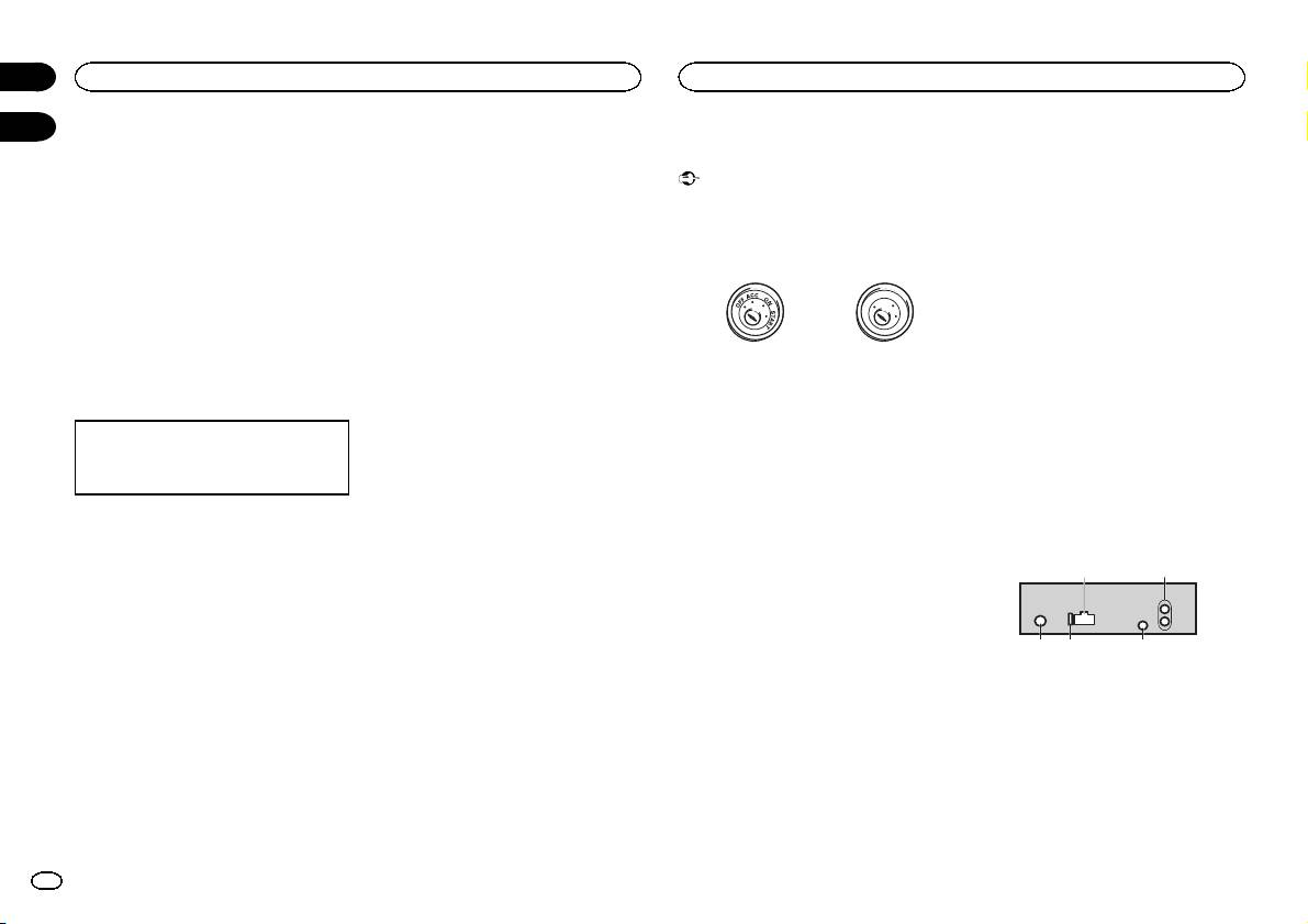
ACC position No ACC position
(auxiliary input) on the previous page.
power terminal of an external power amp.
! Use of this unit in conditions other than the
Also, never connect it to the power terminal
following could result in fire or malfunction.
of the auto antenna. Doing so may result in
Switching the display
— Vehicles with a 12-volt battery and negative
battery drain or a malfunction.
grounding.
! The black cable is ground. Ground cables for
Selecting the desired text information
— Speakers with 50 W (output value) and 4 W to
this unit and other equipment (especially,
1 Press DISP to cycle between the following:
8 W (impedance value).
high-current products such as power amps)
! Source name
! To prevent a short-circuit, overheating or mal-
must be wired separately. If they are not, an
! Source name and clock
function, be sure to follow the directions
accidental detachment may result in a fire or
below.
malfunction.
— Disconnect the negative terminal of the bat-
If an unwanted display appears
tery before installation.
This unit
— Secure the wiring with cable clamps or adhe-
Turn off the unwanted display using the proce-
sive tape. Wrap adhesive tape around wiring
dures listed below.
that comes into contact with metal parts to
protect the wiring.
1 Press M.C. to display the main menu.
— Place all cables away from moving parts,
such as the shift lever and seat rails.
2 Turn M.C. to change the menu option
— Place all cables away from hot places, such
and press to select SYSTEM.
as near the heater outlet.
— Do not connect the yellow cable to the battery
3 Turn M.C. to display DEMO OFF and press
by passing it through the hole to the engine
to select.
compartment.
— Cover any disconnected cable connectors
4 Turn M.C. to switch to YES.
with insulating tape.
— Do not shorten any cables.
5 Press M.C. to select.
— Never cut the insulation of the power cable of
this unit in order to share the power with
other devices. The current capacity of the
cable is limited.
— Use a fuse of the rating prescribed.
3 45
Section
02
Operating this unit
Installation
03
21
1 Power cord input
2 Rear output or subwoofer output
3 Antenna input
4 Fuse (10 A)
5 Wired remote input
Hard-wired remote control adapter can be
connected (sold separately).
8
En
