Dell Latitude D510: Display Assembly and Display Latch
Display Assembly and Display Latch : Dell Latitude D510
Back to Contents Page
Display Assembly and Display Latch
Dell™Latitude™D510ServiceManual
Display Assembly
Display Bezel
Display Panel
Display Latch
Display Assembly
1. Follow the instructions in "Preparing to Work Inside Your Computer."
2. Remove the keyboard.
3. Open the display assembly approximately 180 degrees, and support the display assembly so that it does not open past this position.
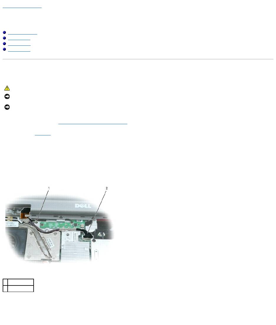
4. Remove the captive screw that grounds the display cable.
5. Disconnect the display cable from the display cable connector on the system board.
6. Release the display cable from its routing clips and slide it out from beneath the tab on the palm rest.
7. Release the two antenna cables from the two antenna-securing clips.
8. Disconnect one antenna cable from the display by holding the two gold antenna connectors and gently pulling them apart. Then disconnect the other
antenna cable. (The gold antenna connectors on each cable are keyed to ensure that they are correctly reconnected.)
CAUTION: Before performing the following procedures, read the safety instructions in your Product Information Guide.
NOTICE: To prevent damage to components inside your computer, discharge static electricity from your body before you touch any of your computer's
electronic components. You can do so by touching an unpainted metal surface.
NOTICE: You must remove the display assembly before you remove the palm rest.
1
captive screw
2
display cable
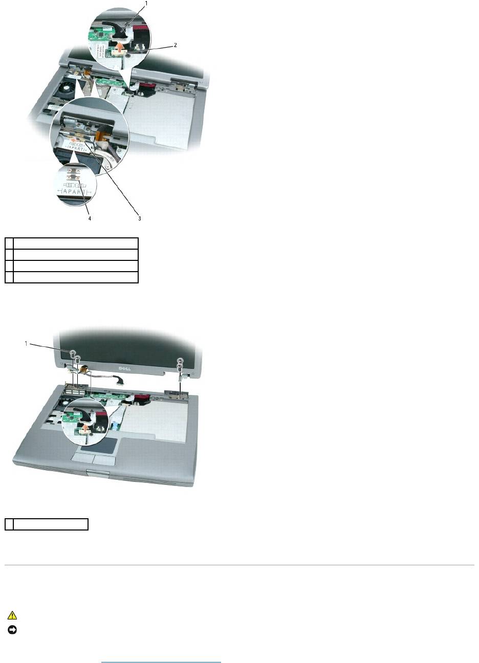
9. Remove the four M2.5 x 5-mm screws.
10. Rotate the display assembly to a 90-degree angle, and lift the display assembly up and out of the computer base.
Display Bezel
1. Follow the instructions in "Preparing to Work Inside Your Computer."
1
display cable
2
display cable connector on system board
3
antenna cables (2)
4
antenna securing clips (2)
1
M2.5 x 5-mm screws (4)
CAUTION: Before performing the following procedures, read the safety instructions in your Product Information Guide.
NOTICE: To prevent damage to components inside your computer, discharge static electricity from your body before you touch any of your computer's
electronic components. You can do so by touching an unpainted metal surface.
2. Remove the keyboard.
3. Remove the display assembly.
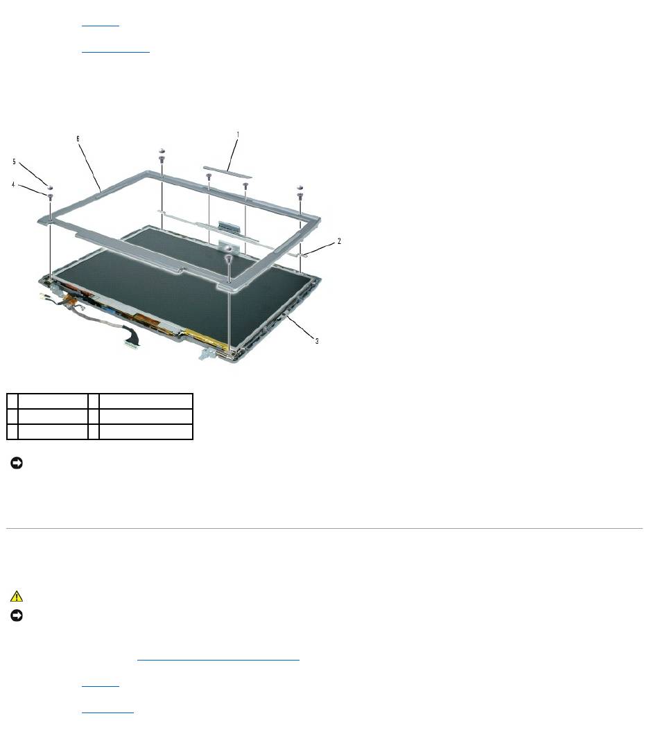
4. Use a plastic scribe to pry the five display bumpers out of the screw holes located on the front of the bezel.
5. Remove the six M2 x 5-mm screws located on the front of the bezel.
6. Starting at the edges of the bottom of the display panel, use your fingers to separate the bezel from the top cover by lifting the inside edge of the bezel
away from the top cover.
Display Panel
1. Follow the instructions in "Preparing to Work Inside Your Computer."
2. Remove the keyboard.
3. Remove the display bezel.
4. Remove the eight M2 x 5-mm screws from the display panel.
1
display bumper
4
M2 x 5-mm screws (6)
2
support bracket
5
display bumpers (4)
3
display panel
6
display bezel
NOTICE: Carefully separate the bezel from the top cover to avoid damage to the bezel.
CAUTION: Before performing the following procedures, read the safety instructions in your Product Information Guide.
NOTICE: To prevent damage to components inside your computer, discharge static electricity from your body before you touch any of your computer's
electronic components. You can do so by touching an unpainted metal surface.
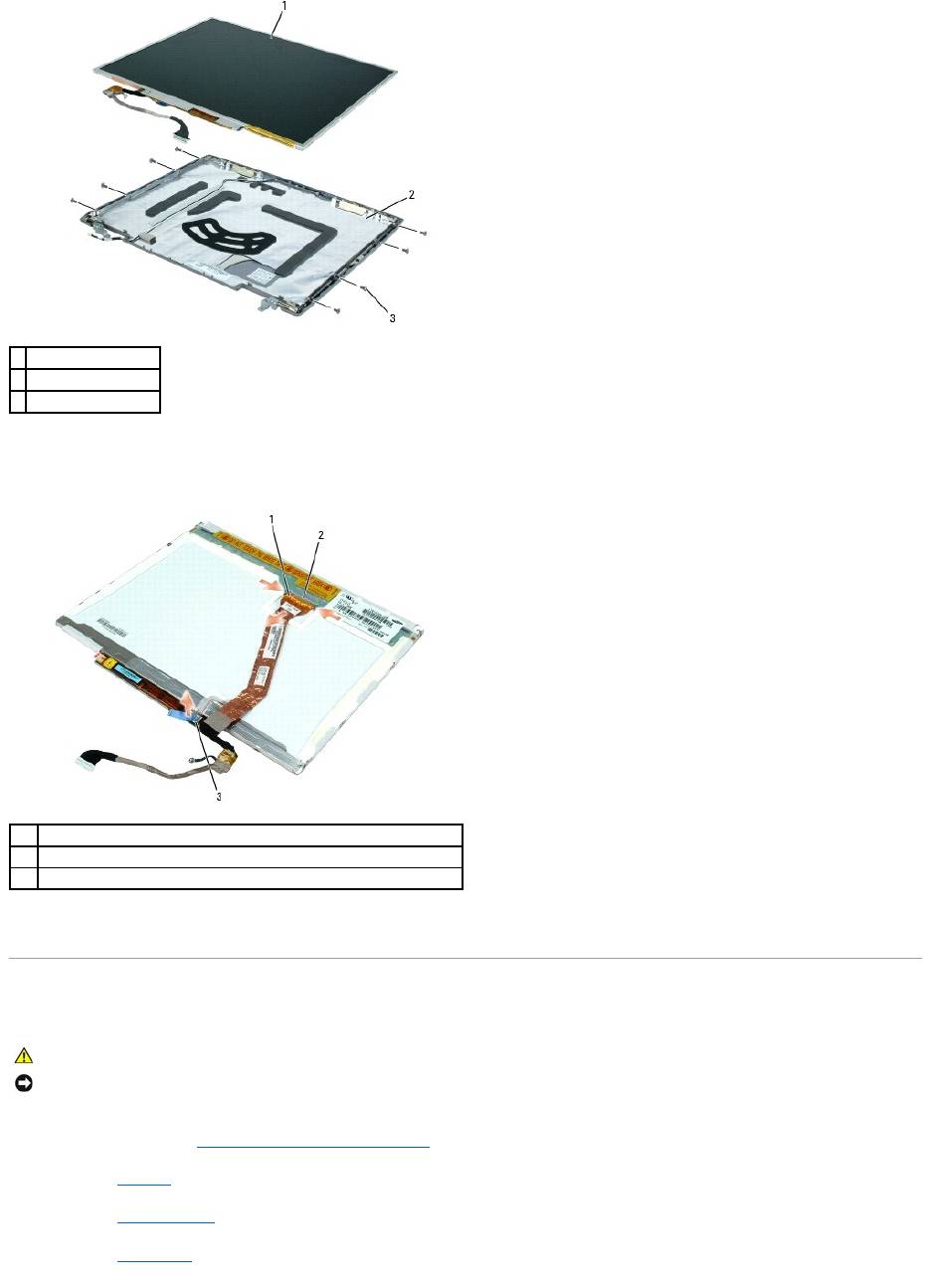
5. Lift the display panel, rotating it out of the display cover.
6. Use the pull-tab to disconnect the bottom flex-cable connector from the inverter connector.
7. Press in both sides of the top flex-cable connector, and pull it away from the display connector.
Display Latch
1. Follow the instructions in "Preparing to Work Inside Your Computer."
2. Remove the keyboard.
3. Remove the display assembly.
4. Remove the display bezel.
1
display panel
2
top cover
3
M2 x 5-mm screws (8)
1
top flex-cable connector
2
display connector
3
bottom flex-cable connector with pull-tab
CAUTION: Before performing the following procedures, read the safety instructions in your Product Information Guide.
NOTICE: To prevent damage to components inside your computer, discharge static electricity from your body before you touch any of your computer's
electronic components. You can do so by touching an unpainted metal surface.
5. Remove the display panel.
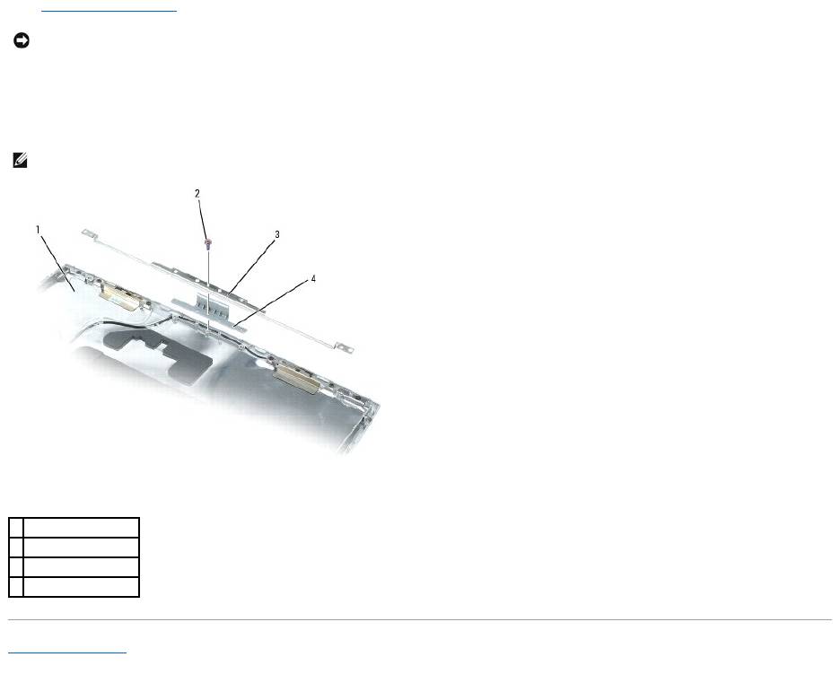
6. Remove the M2 x 4-mm screw that secures the support bracket to the top cover.
7. Lift the support bracket out of the top cover, and then remove the display latch.
Back to Contents Page
NOTICE: A strip of copper foil may be present beneath the support bracket on some systems; ensure that you do not tear this foil while removing the
bracket.
NOTE: Ensure that the support bracket is upright when you replace the display latch.
1
top cover
2
M2 x 4-mm screw (1)
3
support bracket
4
display latch
Оглавление
- Dell™Latitude™D510ServiceManual
- Before You Begin
- Flashing the BIOS
- Internal Card With Bluetooth®Wireless Technology
- Coin Cell Battery
- Microprocessor Module
- Display Assembly and Display Latch
- Fan
- Hard Drive
- Keyboard
- Base Latch
- Palm Rest
- Pin Assignments for I/O Connectors
- Speakers
- System Board
- System Components
- Microprocessor Thermal-Cooling Assembly
- Memory Module, Modem, Mini PCI Card, and Optical Devices
