Dell Latitude D510: Microprocessor Module
Microprocessor Module : Dell Latitude D510
Back to Contents Page
Microprocessor Module
Dell™Latitude™D510ServiceManual
Removing the Microprocessor Module
Installing the Microprocessor Module
Removing the Microprocessor Module
1. Follow the instructions in "Preparing to Work Inside Your Computer."
2. Remove the keyboard.
3. Remove the microprocessor thermal-cooling assembly.
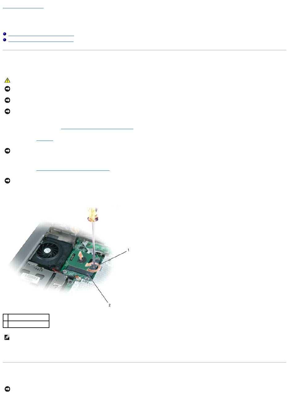
4. Use a small, flat-blade screwdriver to rotate the ZIF-socket cam screw counterclockwise until it comes to the cam stop.
5. Lift out the microprocessor module.
Installing the Microprocessor Module
CAUTION: Before performing the following procedures, read the safety instructions in your Product Information Guide.
NOTICE: To prevent damage to components inside your computer, discharge static electricity from your body before you touch any of your computer's
electronic components. You can do so by touching an unpainted metal surface.
NOTICE: Do not touch the processor die. Press and hold the microprocessor down on the substrate on which the die is mounted while turning the cam
screw to prevent intermittent contact between the cam screw and microprocessor.
NOTICE: To avoid damage to the microprocessor, hold the screwdriver so that it is perpendicular to the microprocessor when turning the cam screw.
NOTICE: To ensure maximum cooling for the microprocessor, do not touch the heat transfer areas on the microprocessor thermal-cooling assembly. The
oils in your skin reduce the heat transfer capability of the thermal pads.
NOTICE: When removing the microprocessor module, pull the module straight up. Be careful not to bend the pins on the microprocessor module.
1
ZIF socket cam screw
2
pin-1 corner
NOTE: The ZIF-socket cam screw secures the microprocessor to the system board. Take note of the arrow on the ZIF-socket cam screw.
NOTICE: Ensure that the cam lock is in the fully open position before seating the microprocessor module. Seating the microprocessor module properly in
the ZIF socket does not require force.

1. Align the pin-1 corner of the microprocessor module with the pin-1 corner of the ZIF socket, and insert the microprocessor module.
When the microprocessor module is correctly seated, all four corners are aligned at the same height. If one or more corners of the module are higher
than the others, the module is not seated correctly.
2. Tighten the ZIF socket by turning the cam screw clockwise to secure the microprocessor module to the system board.
3. Replace the parts that you removed in Removing the Microprocessor Module.
Back to Contents Page
NOTICE: A microprocessor module that is not properly seated can result in an intermittent connection or permanent damage to the microprocessor and
ZIF socket.
NOTE: The pin-1 corner of the microprocessor module has a triangle that aligns with the triangle on the pin-1 corner of the ZIF socket.
NOTICE: You must position the microprocessor module correctly in the ZIF socket to avoid permanent damage to the module and the socket.
Оглавление
- Dell™Latitude™D510ServiceManual
- Before You Begin
- Flashing the BIOS
- Internal Card With Bluetooth®Wireless Technology
- Coin Cell Battery
- Microprocessor Module
- Display Assembly and Display Latch
- Fan
- Hard Drive
- Keyboard
- Base Latch
- Palm Rest
- Pin Assignments for I/O Connectors
- Speakers
- System Board
- System Components
- Microprocessor Thermal-Cooling Assembly
- Memory Module, Modem, Mini PCI Card, and Optical Devices
