Dell Precision 350: System Board
System Board : Dell Precision 350
Back to Contents Page
System Board
DellPrecision™Workstation350ServiceManual
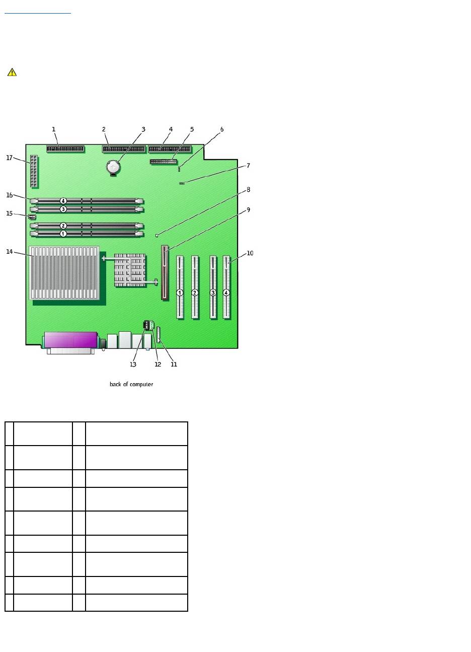
System Board Components
System Board Jumpers
CAUTION: Before you begin any of the procedures in this section, follow the safety instructions in the System Information Guide.
1
floppy drive
connector
(FLOPPY)
10
PCI card connectors (PCI1, PCI2,
PCI3, and PCI4)
2
CD/DVD drive
connector (SEC
IDE)
11
front-panel audio cable connector
(FNT PNL AUD)
3
battery socket
(BATTERY)
12
telephony connector (TELE)
4
hard drive
connector (PRI
IDE)
13
CD drive audio cable connector
(CD)
5
front-panel
connector (FNT
PNL)
14
microprocessor and heat sink
connector (J2E1)
6
password jumper
(PSWD)
15
microprocessor fan connector
(FAN2)
7
clear CMOS
jumper (CLR CM)
16
memory module connectors
(RIMM 1, RIMM 2, RIMM 3, and
RIMM 4)
8
standby power
light (PWR LED)
17
power connector (MAIN POWER)
9
AGP card
connector (J7C1)
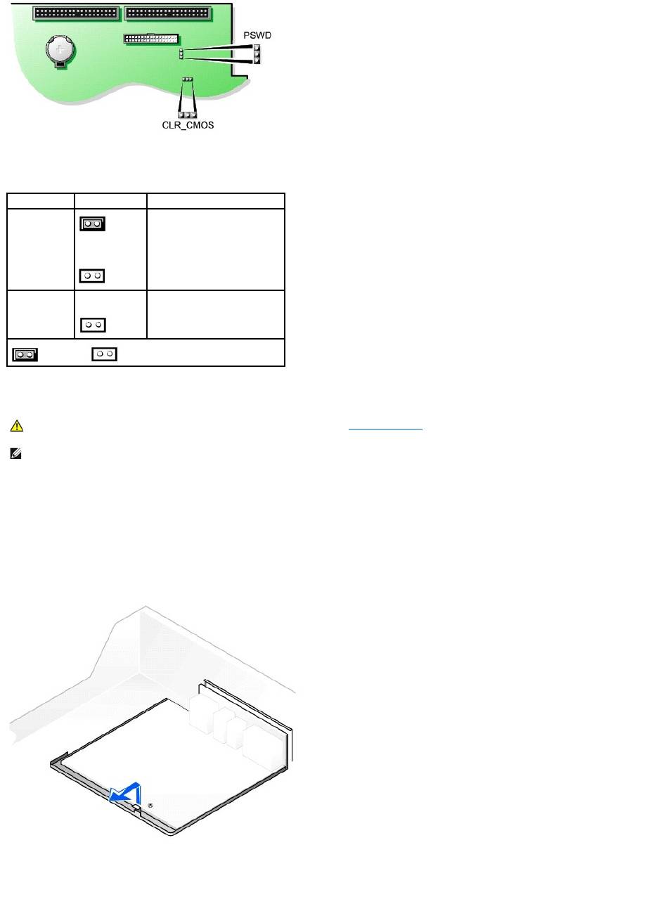
System-Board Jumper Settings
Removing the System Board
1. Remove any components that restrict access to the system board.
2. Disconnect all cables from the system board.
3. Before you remove the existing system board, visually compare the replacement system board to the existing system board to make sure that you have
the correct part.
4. Pull up on the tab and slide the system board toward the front of the computer, and then lift it up and away.
Removing the System Board
5. Place the system board that you just removed next to the replacement system board.
Replacing the System Board
Jumper
Setting
Description
PSWD
(green jumper)
(default)
Password features are enabled.
Password features are disabled.
CLR_CMOS
Clears the CMOS settings
jumpered unjumpered
CAUTION: Before you remove any component from the system board, see "Before You Begin."
NOTE: The system board and metal tray are attached and are removed as one piece.
1. Transfer components from the existing system board to the replacement system board.
2. Remove the memory modules and install them on the replacement board.
3. Remove the heat-sink assembly and microprocessor from the existing system board and transfer them to the replacement system board.
4. Configure the settings of the replacement system board.
5. Set the jumpers on the replacement system board so they are identical to the ones on the existing board.
6. Orient the replacement board by aligning the notches on the bottom to the tabs on the computer floor.
7. Slide the board toward the back of the computer until it clicks into place.
8. Replace any components and cables that you removed from the system board.
Back to Contents Page
CAUTION: The microprocessor package and heat-sink assembly can get hot. To avoid burns, be sure that the package and assembly have had
sufficient time to cool before you touch them.
NOTE: Some components and connectors on the replacement system board may be in different locations from the corresponding connectors on the
existing system board.
