Pioneer DEH-X9500BT: Power cord This unit
Power cord This unit: Pioneer DEH-X9500BT
Table of contents
Important
— Never wire the negative speaker cable directly
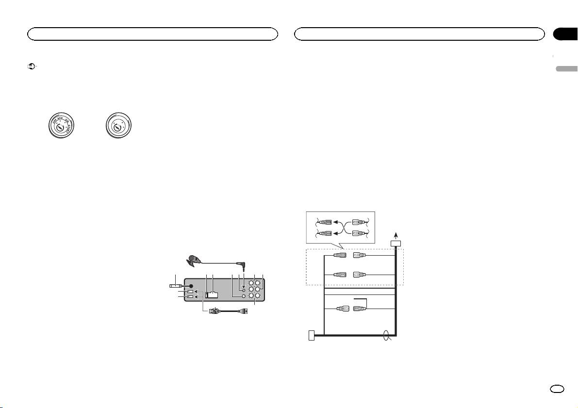
Hard-wired remote control adapter can be
! When installing this unit in a vehicle without
to ground.
connected (sold separately).
an ACC (accessor y) position on the ignition
— Never band together negative cables of multi-
7 Microphone input (DEH-X9500BT only)
switch, failure to connect the red cable to the
ple speakers.
8 Microphone (DEH-X9500BTonly)
terminal that detects operation of the ignition
! When this unit is on, control signals are sent
4m
key may result in battery drain.
through the blue/white cable. Connect this
9 Rear output
cable to the system remote control of an ex-
a Front output
ternal power amp or the vehicle’s auto-anten-
F
O
b Subwoofer output
F
N
O
S
T
na relay control terminal (max. 300 mA
c USB cable
R
A
T
12 V DC). If the vehicle is equipped with a
1.5 m
glass antenna, connect it to the antenna
! If connecting both USB1 (USB storage
ACC position No ACC position
booster power supply terminal.
device1)/iPod1 (iPod connected using
! Use of this unit in conditions other than the
! Never connect the blue/white cable to the
USB input1) and USB2 (USB storage de-
following could result in fire or malfunction.
power terminal of an external power amp.
vice2)/iPod2 (iPod connected using USB
— Vehicles with a 12-volt battery and negative
Also, never connect it to the power terminal
input2) at the same time, use a Pioneer
grounding.
of the auto antenna. Doing so may result in
USB cable (CD-U50E) in addition to the
— Speakers with 50 W (output value) and 4 W to
battery drain or a malfunction.
regular Pioneer USB cable.
8 W (impedance value).
! The black cable is ground. Ground cables for
! To prevent a short-circuit, overheating or mal-
this unit and other equipment (especially,
function, be sure to follow the directions
high-current products such as power amps)
Power cord
below.
must be wired separately. If they are not, an
accidental detachment may result in a fire or
3
4
— Disconnect the negative terminal of the bat-
tery before installation.
malfunction.
— Secure the wiring with cable clamps or adhe-
1
sive tape. Wrap adhesive tape around wiring
2
5
6
This unit
that comes into contact with metal parts to
protect the wiring.
8
— Place all cables away from moving parts,
3
4
such as the shift lever and seat rails.
3 4 596 a
7
— Place all cables away from hot places, such
7
5
6
as near the heater outlet.
8
— Do not connect the yellow cable to the battery
2
9
by passing it through the hole to the engine
1
c
compartment.
c
b
— Cover any disconnected cable connectors
a
b
with insulating tape.
1 USB port 1
— Do not shorten any cables.
2 USB port 2
e
— Never cut the insulation of the power cable of
3 Antenna input
this unit in order to share the power with
15 cm
other devices. The current capacity of the
4 Fuse (10 A)
cable is limited.
5 Power cord input
— Use a fuse of the rating prescribed.
6 Wired remote input
d
Section
Connections
Connections
02
2 Depending on the kind of vehicle, the func-
tion of 3 and 5 may be different. In this
English
case, be sure to connect 4 to 5 and 6 to
3.
3 Yellow
Back-up (or accessory)
4 Yellow
Connect to the constant 12 V supply termi-
nal.
5 Red
Accessory (or back-up)
6 Red
Connect to terminal controlled by ignition
switch (12 V DC).
7 Connect leads of the same color to each
other.
8 Orange/white
Connect to lighting switch terminal.
9 Black (chassis ground)
a Blue/white
The pin position of the ISO connector will dif-
fer depending on the type of vehicle. Connect
a and b when Pin 5 is an antenna control
type. In another type of vehicle, never con-
nect a and b.
b Blue/white
Connect to system control terminal of the
power amp (max. 300 mA 12 V DC).
c Blue/white
Connect to auto-antenna relay control termi-
nal (max. 300 mA 12 V DC).
d Speaker leads
White: Front left +
White/black: Front left *
Gray: Front right +
Gray/black: Front right *
Green: Rear left + or subwoofer +
Green/black: Rear left * or subwoofer *
Violet: Rear right + or subwoofer +
Violet/black: Rear right * or subwoofer *
1 To power cord input
e ISO connector
In some vehicles, the ISO connector may be
divided into two. In this case, be sure to con-
nect to both connectors.
En
3
