Dell PowerEdge 1950: Installing System Components
Installing System Components: Dell PowerEdge 1950

3
Installing System Components
This section describes how to install the following system components:
• Cooling fan modules
• Cooling shrouds
• Power supplies
• SAS controller daughter card or SAS RAID controller daughter card
• RAID battery
• RAID controller expansion card
• Expansion cards
• Boot drive
• System memory
• Processors
• RAC card
• Optical drive
• Hard drives
• SAS backplane boards
•Risers
• Sideplane board
• System battery
• Control panel assembly
• System board
Installing System Components 43
Recommended Tools
You may need the following items to perform the procedures in this section:
• Key to the system keylock
• #2 Phillips screwdriver
• T10 Torx driver
• Small flat-blade screwdriver
• Wrist grounding strap
Inside the System
CAUTION: Many repairs may only be done by a certified service technician. You should only perform
troubleshooting and simple repairs as authorized in your product documentation, or as directed by the online or
telephone service and support team. Damage due to servicing that is not authorized by Dell is not covered by your
warranty. Read and follow the safety instructions that came with the product.
CAUTION: The memory modules can become extremely hot during normal operation. Allow the modules
sufficient time to cool before handling.
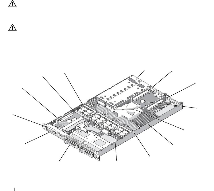
In Figure 3-1, the bezel, system cover, and memory cooling shroud are removed to provide an interior view
of the system.
Figure 3-1. Inside the System
5
4
6
3
7
2
8
1
9
14
10
11
13
12
44 Installing System Components

1 control panel 2 SAS controller daughter card
3 sideplane
or SAS RAID controller
daughter card (optional)
4 cooling fan modules (4) 5 power supply bays (2) 6 left riser (slot 2)
7 center riser (slot 1) 8 battery 9 system board cooling shroud
1
memory modules (8) 11 heatsink/microprocessor (2) 12 backplane
0
1
two 3.5-inch or four 2.5-inch
14 optical slimline drive
3
hard drive bays
(optional)
The system board holds the system's control circuitry and other electronic components. Several hardware
options, such as the microprocessors and memory, are installed directly on the system board. The left and
center risers each have one slot and can accommodate up to two half-length PCI-X cards or two half-length
PCIe expansion cards. For more information, see "Expansion Cards" on page 61.
The system provides space for one optional slimline optical drive. The optical drive tray connects to the
controller on the system board through the sideplane board. For more information, see "Installing the Optical
Drive Tray" on page 74.
The hard-drive bays provide space for up to two 3.5-inch or four 2.5-inch SAS/SATA hard drives. The hard
drives connect to a SAS controller daughter card or a SAS RAID controller daughter card. For more
information, see "Installing a Hot-Plug Hard Drive" on page 76.
During an installation or troubleshooting procedure, you may be required to change a jumper setting. For
more information, see "Jumpers and Connectors" on page 115.
NOTE: There are no hot-pluggable components inside this system except for externally accessible components,
such as the power supplies and the hard drives.
Removing and Replacing the Front Bezel
1
The system is enclosed by an optional bezel. To upgrade or troubleshoot the system, remove the bezel and
cover to access the internal system components. Unless you are installing a hot-plug hard drive, turn off
the system and attached peripherals, and disconnect the system from the electrical outlet and peripherals.
NOTE: You do not need to remove the front bezel to remove the system cover.
2
Using the system key, unlock the bezel.
3
Press the tab at the left end of the bezel.
4
Rotate the left end of the bezel away from the system to release the right end of the bezel.
5
Pull the bezel away from the system. See Figure 3-2.
Installing System Components 45
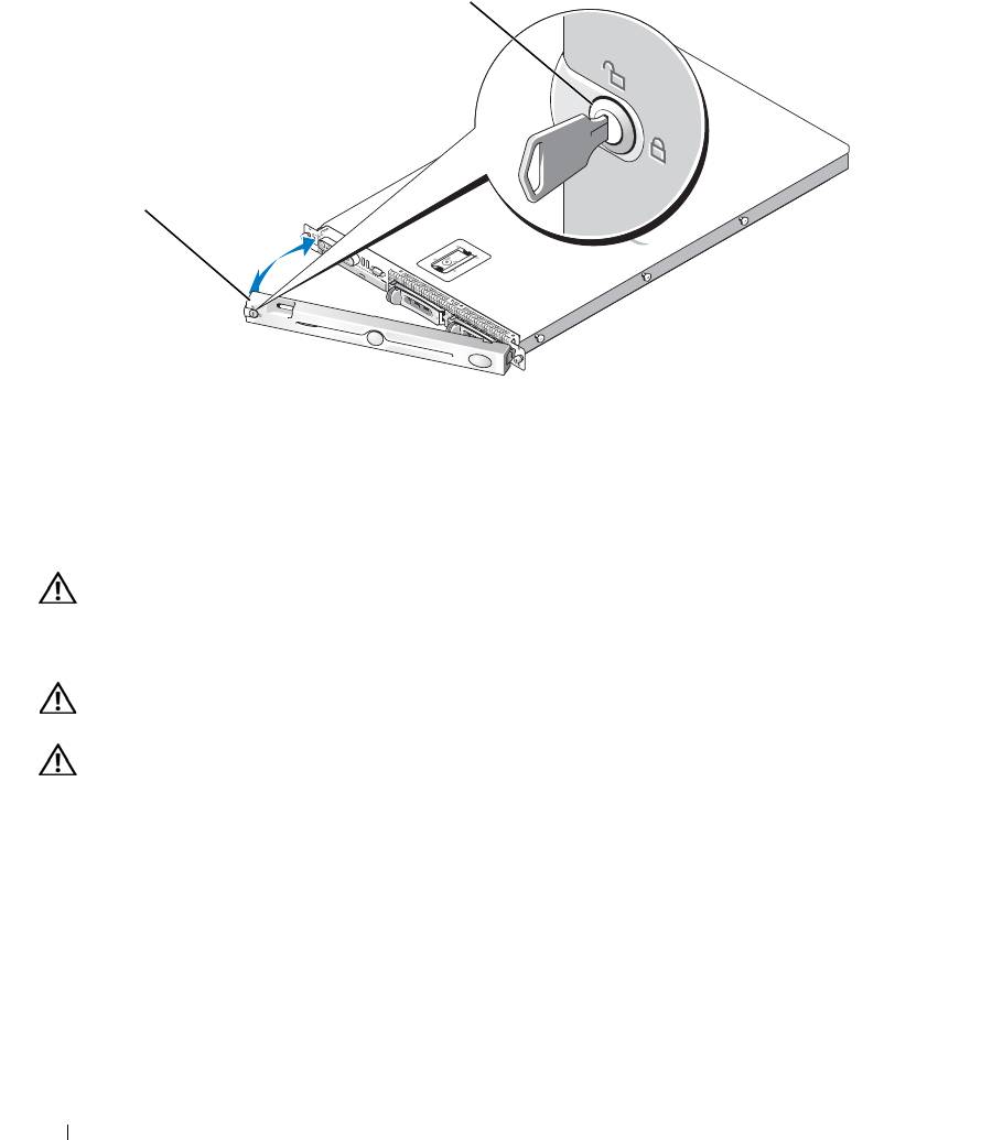
Figure 3-2. Removing the Bezel
1
2
1 key lock 2 bezel cover
To replace the front bezel, perform the preceding steps in reverse.
Opening and Closing the System
CAUTION: Many repairs may only be done by a certified service technician. You should only perform
troubleshooting and simple repairs as authorized in your product documentation, or as directed by the online or
telephone service and support team. Damage due to servicing that is not authorized by Dell is not covered by your
warranty. Read and follow the safety instructions that came with the product.
CAUTION: Whenever you need to lift the system, get others to assist you. To avoid injury, do not attempt to lift
the system by yourself.
CAUTION: The memory modules can become extremely hot during normal operation. Allow the modules
sufficient time to cool before handling.
Opening the System
To upgrade or troubleshoot the system, remove the system cover to gain access to internal components.
1
Turn off the system and attached peripherals, and disconnect the system from the electrical outlet and
peripherals.
2
Remove the bezel. See "Removing and Replacing the Front Bezel" on page 45.
3
To remove the system cover, rotate the latch release lock on the latch in a counter clockwise direction to
the unlocked position. See Figure 3-3.
46 Installing System Components
4
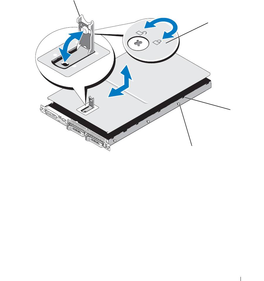
Lift up on the latch on top of the system to guide it back and into an offset position. See Figure 3-3.
5
Grasp the cover on both sides and carefully lift the cover away from the system.
Figure 3-3. Removing the Cover
1
2
3
4
1 latch 2 latch release lock 3 alignment J hooks
4 chassis tabs
Closing the System
1
Lift up the latch on the cover.
2
Place the cover on top of the system and offset the cover slightly back so that it clears the chassis J hooks
and lays flat on the system chassis. See Figure 3-3.
3
Lower the cover into the closed position aligning it with the J hooks and push down on the latch to guide
the cover into place.
4
Rotate the latch release lock in a clockwise direction to secure the cover.
Installing System Components 47
Cooling Fan Modules
This system contains four cooling fan modules, each comprised of two dual-rotor fans, for a total of eight fans
that are connected directly to the system board.
Removing a Cooling Fan Module
CAUTION: Many repairs may only be done by a certified service technician. You should only perform
troubleshooting and simple repairs as authorized in your product documentation, or as directed by the online or
telephone service and support team. Damage due to servicing that is not authorized by Dell is not covered by your
warranty. Read and follow the safety instructions that came with the product.
NOTE: The procedure for removing each individual fan module is the same.
1
Turn off the system and attached peripherals, and disconnect the system from the electrical outlet and
peripherals.
2
Open the system. See "Opening and Closing the System" on page 46.
NOTE: You can remove the fan modules without removing the memory cooling shroud; however, Dell
recommends that you remove this shroud before removing a fan module. Do not remove the system board cooling
shroud.
See "Removing the Memory Cooling Shroud" on page 52.
3
Raise the fan handle, disconnect the module wire harness from the system board, and pull the fan straight
up to clear the chassis. See Figure 3-4.
4
Unplug the fan module connector.
48 Installing System Components
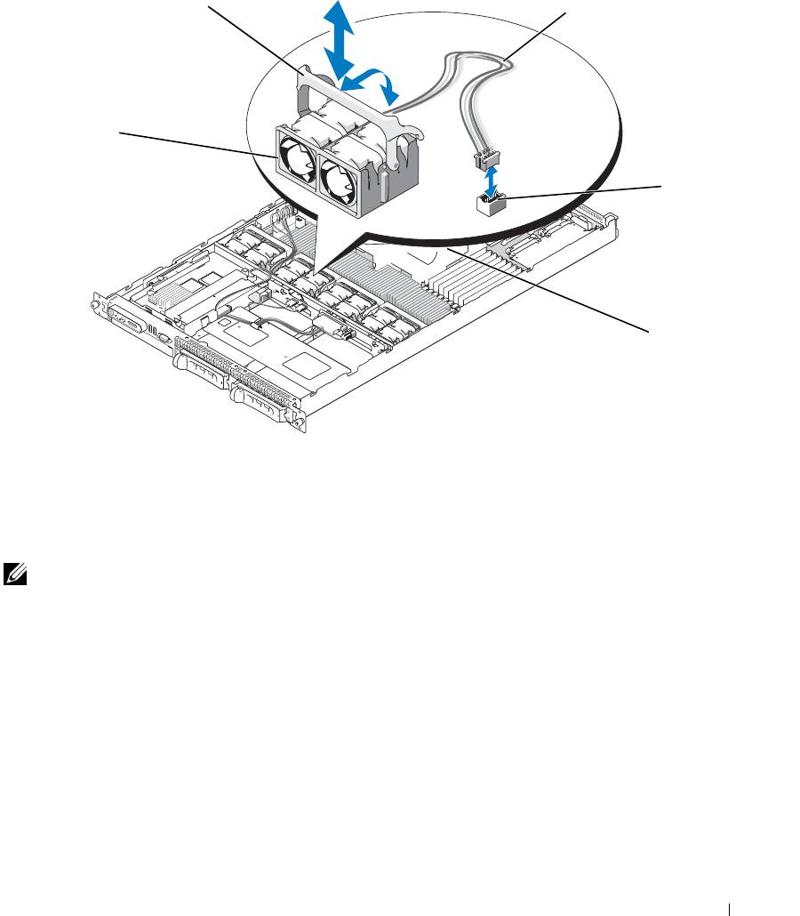
Figure 3-4. Removing and Installing a Cooling Fan
2
3
1
4
5
1 cooling fan modules (4) 2 fan module handles 3 module wire harness
4 cooling fan module connector 5 system board cooling shroud
Replacing a Cooling Fan Module
NOTE: The procedure for installing each individual fan is the same.
1
Ensure that the fan handle is upright and lower the fan into its retention base until the fan is fully seated.
Then lower the fan handle until it snaps into place. See Figure 3-4.
2
Attach the fan module connectors.
3
If you removed the memory cooling shroud to access the fan modules, replace the shroud. See "Replacing
the Memory Cooling Shroud" on page 53.
4
Close the system. See "Opening and Closing the System" on page 46.
Installing System Components 49

Removing the Plastic Fan Guide
NOTE: The plastic fan guide is mounted to the chassis between the fans.
NOTE: You may need to remove the system from the rack.
1
Remove the cooling fan modules. See "Removing a Cooling Fan Module" on page 48.
2
Remove the system from the rack. See the Rack Installation Guide for your system.
3
Place the system upside-down on a flat surface.
4
Using a #2 Phillips screwdriver, remove the two screws from the bottom of the chassis that secure the fan
bracket.
5
Turn the system right-side up, place it on a flat surface, and then remove the fan bracket.
Replacing the Plastic Fan Guide
1
While the system is out of the rack, and with the top cover removed, place the system on its side on a flat
surface.
2
Place the fan bracket into its location inside the chassis.
3
Holding the fan bracket in place, use a #2 Phillips screwdriver to replace the two screws on the bottom of
the chassis.
4
Place the system right-side up on a flat surface.
5
Replace the cooling fan modules. See "Replacing a Cooling Fan Module" on page 49.
6
Replace the system in the rack. See the Rack Installation Guide for your system.
Cooling Shrouds
Your system contains two cooling shrouds.
• System board cooling shroud
• Memory cooling shroud
System Board Cooling Shroud
The
system board cooling shroud directs airflow over the system memory modules, channeling the air from the
four fan modules. See Figure 3-5.
50 Installing System Components
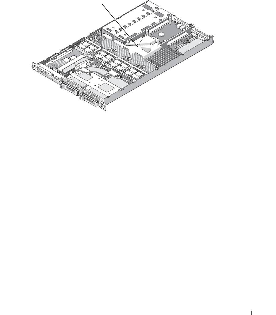
Figure 3-5. System Board Cooling Shroud
1
1 system board cooling shroud
Removing the System Board Cooling Shroud
1
If applicable, remove the bezel. See "Removing and Replacing the Front Bezel" on page 45.
2
Turn off the system and attached peripherals, and then disconnect the system from the electrical outlet.
3
Open the system. See "Opening the System" on page 46.
4
Remove the memory cooling shroud. See "Removing the Memory Cooling Shroud" on page 52.
5
Remove both the center and left risers from the system board. See "Removing an Expansion-Card Riser"
on page 82.
6
Press the tabs on the front side of the shroud (nearest to the processors), and then lift the shroud up and
away from the system.
Installing the System Board Cooling Shroud
1
Align the back of the shroud to the front of the posts of the center and rear card risers on the motherboard.
2
Press down gently on the front of the shroud until it engages with the plastic tabs on the motherboard.
3
Place the center and left risers. See "Installing an Expansion-Card Riser" on page 83.
4
Replace the memory cooling shroud. See "Replacing the Memory Cooling Shroud" on page 53.
5
Close the system. See "Closing the System" on page 47.
Installing System Components 51
6
If applicable, replace the bezel. See "Removing and Replacing the Front Bezel" on page 45.
7
Attach any peripherals, connect the system to the electrical source, and then turn on the system.
Memory Cooling Shroud
The memory cooling shroud covers both the memory modules (DIMMs) and the processors. This shroud can be
removed and installed. See Figure 3-6 and "System Board Removal" on page 91.
Removing the Memory Cooling Shroud
CAUTION: Many repairs may only be done by a certified service technician. You should only perform
troubleshooting and simple repairs as authorized in your product documentation, or as directed by the online or
telephone service and support team. Damage due to servicing that is not authorized by Dell is not covered by your
warranty. Read and follow the safety instructions that came with the product.
CAUTION: The memory modules are hot to the touch for some time after the system has been powered down.
Allow time for the memory modules to cool before handling them. Handle the memory modules by the card edges
and avoid touching the components on the memory module.
NOTICE: Never operate your system with the memory cooling shroud removed. Overheating of the system can
develop quickly resulting in a shutdown of the system and the loss of data.
1
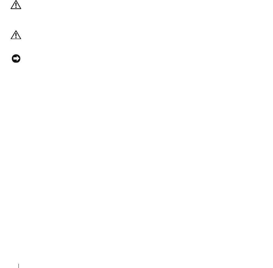
To remove the cooling shroud, locate the release tab on the shroud edge that is nearest to the adjacent
system board shroud. See Figure 3-6.
2
Pull up on the release tab to release the memory cooling shroud.
3
Unseat the shroud from the securing tabs located on the periphery of the shroud.
4
Carefully lift the shroud straight up to disengage it from the system board, and then lift the shroud away
from the system.
52 Installing System Components
Figure 3-6. Memory Cooling Shroud
1
2
3
4
1 memory cooling shroud 2 memory shroud release tab 3 memory modules (8)
4 system processors (2)
Replacing the Memory Cooling Shroud
1
To install the memory cooling shroud, align the shroud directly over the memory modules and the
processors.
2
Using the interior system board cooling shroud as a guide, slowly lower the shroud straight down onto the
system, directly over the processors and memory modules.
3
Gently press around the periphery of the shroud until it engages with the external tabs and snaps into
place.
Power Supplies
Your system supports one or two power supplies rated at an output of 670 W. If only one power supply is
installed, it must be installed in the left power supply bay (bay 1). If two power supplies are installed, the
second power supply serves as a redundant, hot-plug power source.
NOTICE: In a non-redundant configuration, the power supply blank must be installed in the unoccupied power
supply bay to ensure proper system cooling. See "Installing the Power Supply Blank" on page 56.
Installing System Components 53
Removing a Power Supply
NOTICE: The system requires one power supply for the system to operate normally. The system is in the
redundant mode when two power supplies are installed and both power supplies are connected to an AC power
source. Remove and replace only one power supply at a time in a system that is powered on. Operating the system
with only one power supply installed and without a power supply blank installed for extended periods of time can
cause the system to overheat.
NOTICE: If only one power supply is installed, it must be installed in the left power supply bay (1).
NOTICE: If you connect the system to a power source in the range of 120 to 220 VAC, and if two power supplies
are installed, the second power supply serves as a redundant, hot-plug power source.
NOTE: On your rack system, you may have to unlatch and lift the cable management arm if it interferes with
power supply removal. For information about the cable management arm, see the system’s Rack Installation
Guide.
1
If your system has a single power supply, turn off the system and all attached peripherals. For a redundant
system, you can leave the system running and proceed to the next step.
2
Disconnect the power cable from the power source.
3
Disconnect the power cable from the power supply and remove the cable from the cable retention bracket.
NOTICE: On a rack system, you may need to temporarily unlatch and lift the cable management arm. For
information about the cable management arm, see the system’s Rack Installation Guide.
4
Release the locking tab on the left side of the power supply by pressing in toward the right until the power
supply is released from the chassis. See Figure 3-7.
5
Holding the power-supply handle, pull the power supply straight out to clear the chassis.
54 Installing System Components
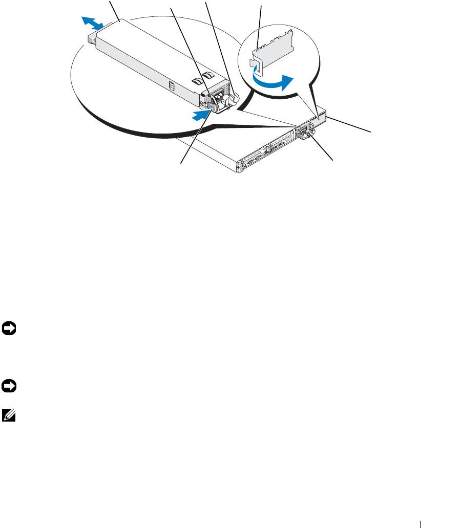
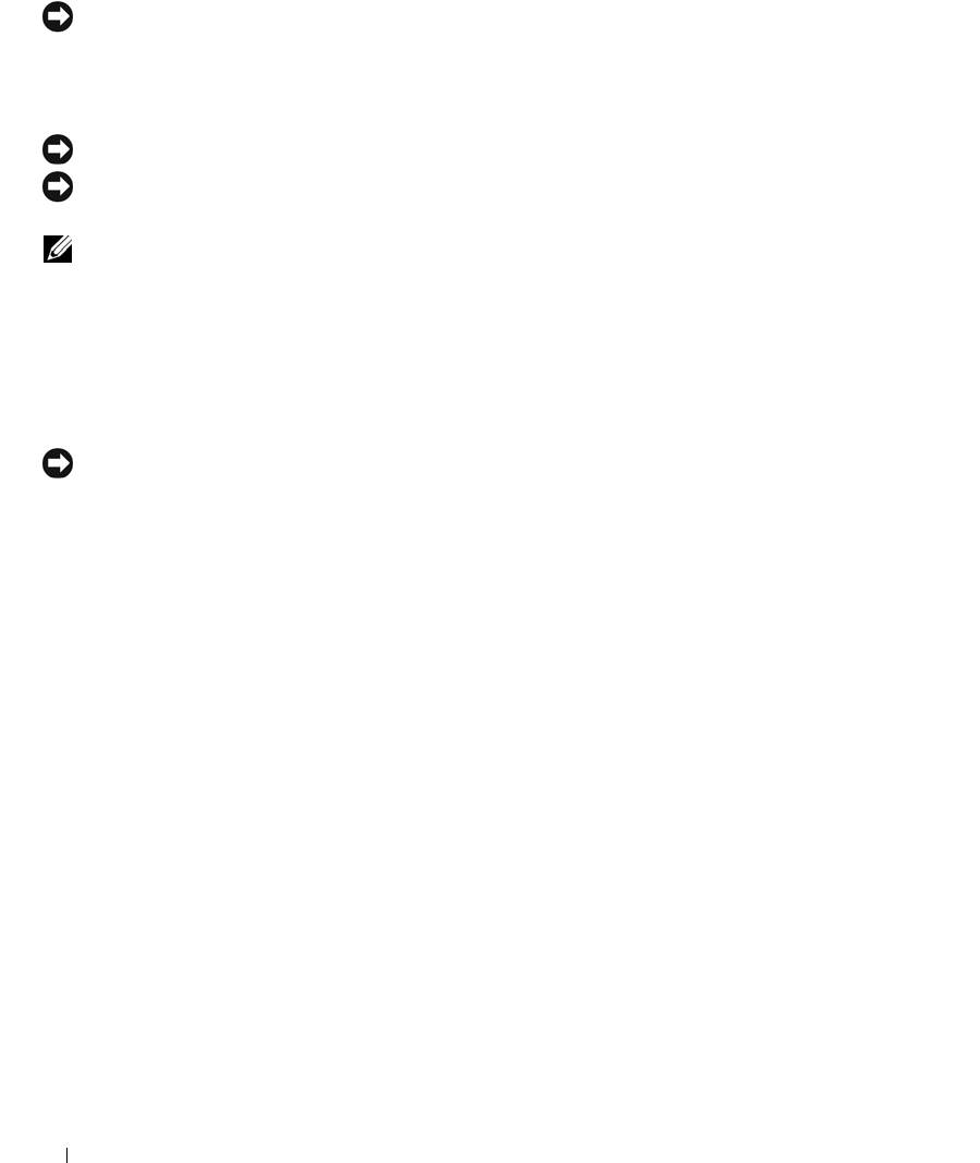
Figure 3-7. Removing and Installing a Power Supply
3
1
2
4
5
6
7
1 power-supply 2 power-supply handle 3 cable retention bracket
4 power supply blank 5 power-supply bay 2 (optional) 6 redundant power supply bay 1
7 locking tab
Replacing a Power Supply
1
If you are adding a second power supply, remove the power supply blank. See "Removing a Power
Supply" on page 54.
2
Holding the power-supply handle, slide the new power supply into the chassis until it is fully seated and
contacts the system chassis. See Figure 3-7.
NOTICE: On a rack system, you may need to temporarily unlatch and lift the cable management arm. For
information about the cable management arm, see the system’s Rack Installation Guide.
3
Insert the power cable through the cable retention bracket, connect the power cable to the power supply,
and plug the cable into a power outlet.
NOTICE: For more information about the power cable retention bracket, see the Getting Started With Your
System guide.
NOTE: After installing a new power supply in a system with two power supplies, allow several seconds for the
system to recognize the power supply and determine its status. The power-supply status indicator turns green to
signify that the power supply is functioning properly (see Figure 1-4).
Installing System Components 55
Removing the Power Supply Blank
Press the latch on the left side to release and remove the blank, rotating the blank slightly to clear the bay,
and remove from the chassis.
NOTICE: To ensure proper system cooling, the power supply blank must be installed on the unoccupied power
supply bay in a non-redundant configuration. Remove the power supply blank only if you are installing a second
power supply.
Installing the Power Supply Blank
To install the power supply blank, insert the tab on the right edge of the blank into the slot in the power
supply bay wall. Rotate the blank into the power supply bay until it is fully seated.
SAS Controller Daughter Card
Your system includes a dedicated slot on the sideplane for an optional SAS controller daughter card. The
SAS controller daughter card provides the SAS storage subsystem for your system’s two optional internal
hard drives. The optional SAS RAID controller daughter card allows you to set up any internal hard drives
in a RAID configuration.
Removing a SAS Controller Daughter Card
1
If you are removing a SAS RAID controller daughter card, disconnect the battery cable from the card by
releasing the tab on the cable connector on the daughter card. See Figure 3-26.
2
Pull on the release latch on the daughter card (see Figure 3-8) and slide the daughter card tray towards the
hard drives.
3
Continue to hold the guide rails outward as you pull the SAS controller daughter card upward from the
rails.
Installing a SAS Controller Daughter Card or SAS RAID Controller Daughter Card
NOTICE: If you are installing a SAS RAID daughter card, be careful not to press on the memory module on the
card (see Figure ). to avoid damaging the memory module or its socket.
NOTICE: If you are installing a new or replacement SAS RAID daughter card, do not remove the card’s plastic
cover until you have completed installing the card.
1
Hold the metal daughter card tray by its edges with the release latch and edge connector facing the
sideplane board. See Figure 3-8.
2
Align the two slots in the daughter card tray and the corresponding tabs on the chassis, then lower the card
tray onto the chassis.
3
Slide the daughter card tray towards the sideplane until the edge connector on the daughter card fits into
the socket on the sideplane board and the release latch engages. See Figure 3-8.
56 Installing System Components
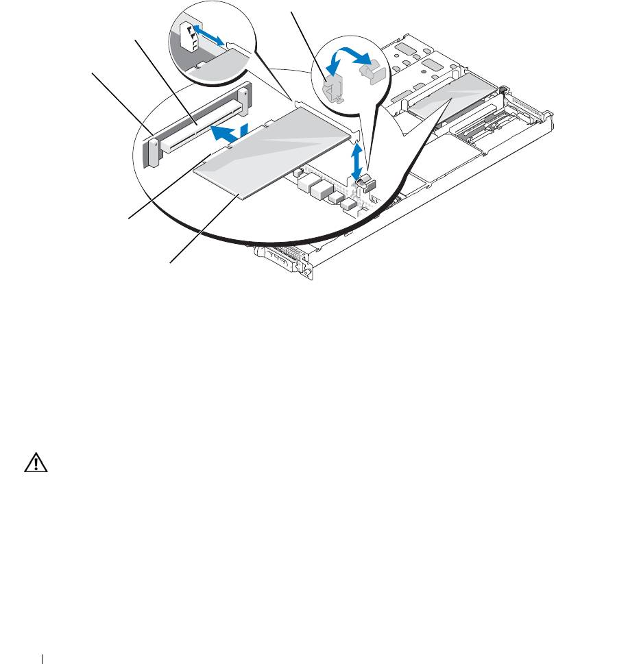
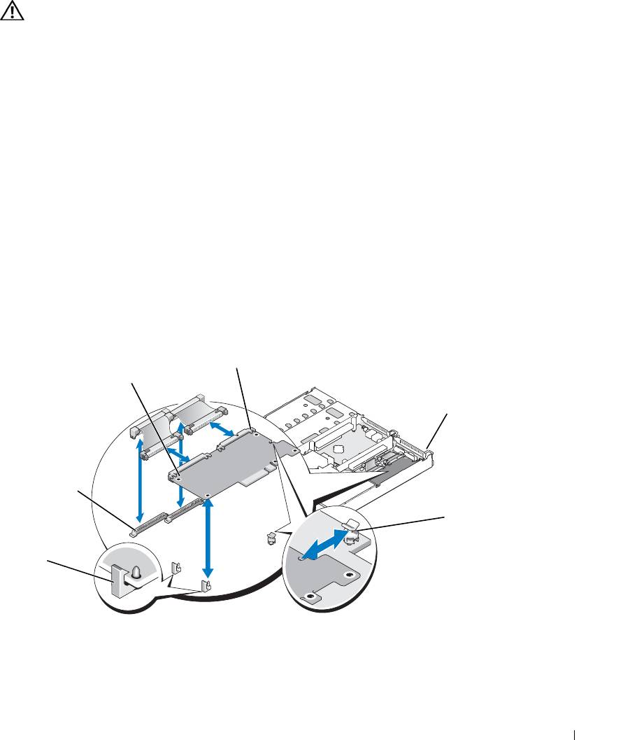
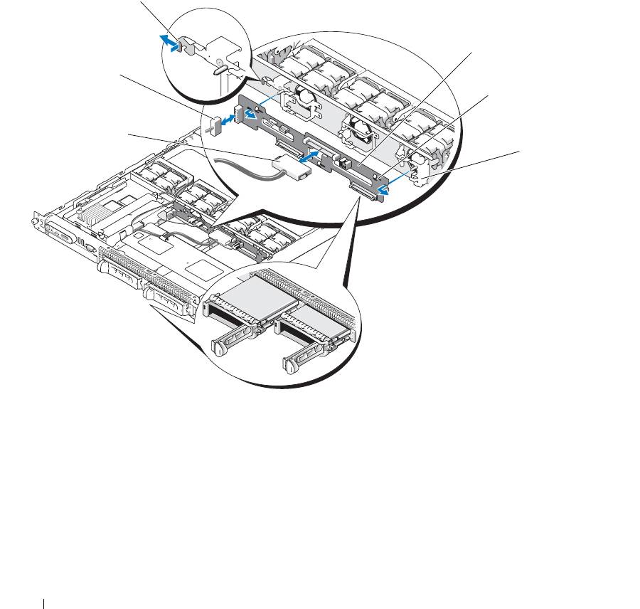
Figure 3-8. Installing a SAS Controller Daughter Card
4
3
2
5
1
6
7
8
1 SAS controller daughter card
2 sideplane 3 daughter card socket
and tray assembly
4 release latch 5 RAID battery connector (SAS
6 RAID memory module
RAID controller daughter card
(DIMM) (SAS RAID
only)
controller daughter card only)
7 SAS RAID connector 0 (to
8 alignment slots in card tray (2)
backplane SAS A)
4
Attach any cables from the internal storage daughter card to the backplane, referring to Figure 3-9 and
Figure 3-10 for the cabling guidelines for your system’s card and backplane configuration.
NOTICE: You must follow the cabling diagrams for connecting the hard drives to either of the internal storage
daughter cards that are illustrated in the following figures to ensure proper connection. Figure 3-9 illustrates the
cable routing for the SAS controller daughter card and Figure 3-10 illustrates the cable routing for the SAS RAID
controller daughter card.
Installing System Components 57
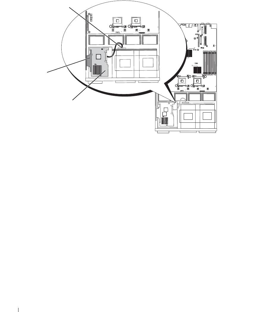
Figure 3-9. Cable Routing for the SAS Controller Daughter Card
3
2
1
1 SAS connector SAS 0 2 SAS controller daughter card 3 SAS backplane connector
SAS A
58 Installing System Components
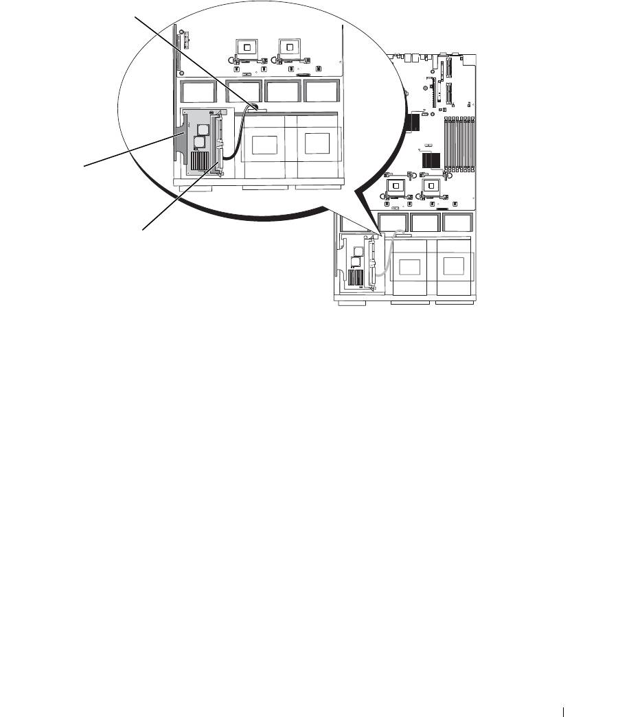
Figure 3-10. Cable Routing for the SAS RAID Controller Daughter Card
3
2
1
1 SAS RAID connector SAS 0 2 SAS RAID controller
3 SAS backplane connector
daughter card
SAS A
Installing System Components 59
RAID Battery
Installing a RAID Battery
1
Locate the RAID battery pocket on the chassis that is adjacent to hard drive bay 0. See Figure 3-11.
2
Insert the battery in the battery pocket.
3
Connect the battery cable to the RAID controller daughter card. See Figure 3-11.
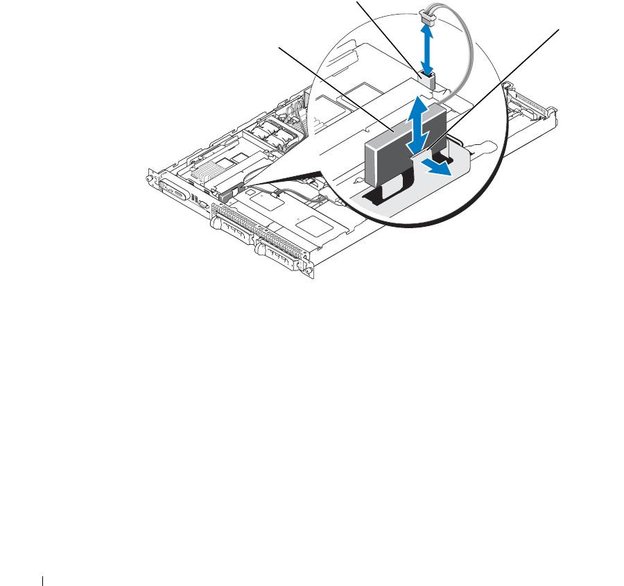
Figure 3-11. Installing a SAS RAID Battery
2
3
1
1 RAID battery 2 SAS RAID daughter card
3 release latch
battery connector
Removing a RAID Battery
1
Disconnect the RAID battery cable from the SAS RAID daughter card. See Figure 3-11.
2
Press the release latch toward the hard-drive bays and remove the battery from the battery pocket.
60 Installing System Components
Expansion Cards
The system is available with one of two optional PCI riser configurations.
PCIe Riser Board Expansion Slots
The PCIe riser configuration provides two PCI Express expansion slots with the following features:
• Two PCIe risers, installed in the left and center riser connectors.
• Two x8-lane PCIe expansion slots.
• Support for full height/half-length PCI cards in both slots.
PCI-X Riser Board Expansion Slots
The PCI-X riser configuration provides two PCI-X slots with the following features:
• Two PCI-X risers, installed in the left and center riser connectors.
• Two PCI-X 64-bit/133-MHz expansion slots (on separate buses).
• Support for full height/half-length PCI cards in both slots.
Expansion Card Installation Guidelines
NOTE: You cannot combine PCIe and PCI-X risers. Two risers must be installed or the system will not power up.
NOTE: The expansion-card slots are not hot-pluggable.
To identify expansion slots, see Figure 3-12. The two expansion card slots are on separate buses.
Installing an Expansion Card
CAUTION: Many repairs may only be done by a certified service technician. You should only perform
troubleshooting and simple repairs as authorized in your product documentation, or as directed by the online or
telephone service and support team. Damage due to servicing that is not authorized by Dell is not covered by your
warranty. Read and follow the safety instructions that came with the product.
1
Unpack the expansion card and prepare it for installation.
For instructions, see the documentation accompanying the card.
2
Turn off the system, including any attached peripherals, and disconnect the system from the electrical
outlet.
3
Open the system. See "Opening and Closing the System" on page 46.
4
If you are adding a new card, open the expansion-card latch and remove the filler bracket. See
Figure 3-12.
5
Install the expansion card:
a
Position the expansion card so that the card-edge connector aligns with the expansion-card connector
on the PCI riser board.
Installing System Components 61
b
Insert the card-edge connector firmly into the expansion-card connector until the card is fully seated.
c
When the card is seated in the connector, close the expansion-card latch. See Figure 3-12.
Figure 3-12. Installing an Expansion Card
3
2
1
5
4
1 PCI riser 2 expansion-card connector 3 expansion-card latch
4 expansion card 5 card-edge connector
6
Connect any cables to the expansion card.
See the documentation that came with the card for information about its cable connections.
7
Close the system. See "Opening and Closing the System" on page 46.
Removing an Expansion Card
CAUTION: Many repairs may only be done by a certified service technician. You should only perform
troubleshooting and simple repairs as authorized in your product documentation, or as directed by the online or
telephone service and support team. Damage due to servicing that is not authorized by Dell is not covered by your
warranty. Read and follow the safety instructions that came with the product.
1
Turn off the system, including any attached peripherals, and disconnect the system from the electrical
outlet.
2
Open the system. See "Opening and Closing the System" on page 46.
3
Disconnect all cables from the card.
62 Installing System Components

4
Remove the expansion card:
a
Open the expansion-card latch. See Figure 3-12.
b
Grasp the expansion card by its edges, and carefully remove it from the expansion-card connector.
5
If you are removing the card permanently, install a metal filler bracket over the empty expansion slot
opening and close the expansion-card latch.
NOTE: You must install a filler bracket over an empty expansion slot to maintain Federal Communications
Commission (FCC) certification of the system. The brackets also keep dust and dirt out of the system and aid
in proper cooling and airflow inside the system.
6
Close the system. See "Opening and Closing the System" on page 46.
Configuring the Boot Device
If you plan to boot the system from a hard drive, the drive must be attached to the primary (or boot)
controller. The device that the system boots from is determined by the boot order specified in the System
Setup program.
The System Setup program provides options that the system uses to scan for installed boot devices. See
"Using the System Setup Program" on page 31 for information about the System Setup program.
Configuring the Boot Drive
The drive or device from which the system boots is determined by the boot order specified in the System Setup
program.
See "Using the System Setup Program" on page 31 for information about the System Setup
program
.
System Memory
You can upgrade your system memory to a maximum of 32 GB by installing 533-MHz or 667-MHz fully
buffered (FB) DDR II memory modules (DIMMs) in sets of 256-MB, 512-MB, 1-GB, 2-GB, or 4-GB modules.
The eight memory sockets are located on the system board under the memory cooling shroud.You can purchase
memory upgrade kits from Dell.
NOTICE: If you remove your original memory modules from the system during a memory upgrade, keep them
separate from any new memory modules that you may have, even if you purchased the new memory modules from
Dell. Use only 533-MHz or 667-MHz DDR II fully buffered DIMMS (FBDs).
The memory module sockets are divided into two equal branches (0 and 1). Each branch consists of two
channels:
• Channel 0 and channel 1 are in branch 0.
• Channel 2 and channel 3 are in branch 1.
Installing System Components 63

Each channel consists of two memory module sockets:
• Channel 0 contains DIMM_1, DIMM_5.
• Channel 1 contains DIMM _2, DIMM_6.
• Channel 2 contains DIMM_3, DIMM_7.
• Channel 3 contains DIMM _4, DIMM _8.
The first DIMM socket of each channel has white release tabs.
General Memory Module Installation Guidelines
To ensure optimal performance of your system, observe the following guidelines when configuring your
system memory.
• Use only qualified FBDs. FBDs can be either s
ingle-ranked
or d
ual-ranked
. FBDs m
arked with a 1R are
single
-r
anked and modules marked with a 2R are dual
-r
anked.
• A minimum of two identical FBDs must be installed.
• DIMM sockets must be populated by lowest number first.
• Memory modules m
ust be installed in pairs of matched memory size, speed, and technology
, and the
total number of memory modules in the configuration must total two, four, or eight. For best system
performance, all four, or eight memory modules should be identical in size, speed, and technology.
•Memory sp
aring and
memory m
irroring require
e
ight memory, and all memory modules must be of
identical memory size, speed, and technology.
• Memory sparing and memory mirroring cannot be implemented at the same time.
Non-Optimal Memory Configurations
System performance can be affected if your memory configuration does not conform to the preceding
installation guidelines. Your system may issue an error message during startup stating that your memory
configuration is non-optimal.
Memory Sparing Support
The system supports memory sparing if eight identical memory modules are installed in the system. The
memory sparing feature must be enabled in the System Setup program and can be used only if memory
mirroring is not enabled.(See "Using the System Setup Program" on page 31.)
Memory sparing allocates four ranks of DIMM memory to the spare bank. These four ranks consist of the
first rank of memory in DIMM sockets 1 through 4. For single-rank DIMMs, the entire capacity of the four
DIMMs is allocated to sparing whereas for dual-rank DIMMs, only half of the four-DIMM capacity is
allocated to sparing. Table 3-1 shows how memory sparing splits the available and spared memory in each
of the single- and dual-ranked memory module combinations.
64 Installing System Components
Table 3-1. Memory Sparing Configurations
DIMMs Size/Type Total Memory Available Spare
8 256-MB single-rank 2 GB 1 GB 1 GB
512-MB single-rank 4 GB 2 GB 2 GB
1-GB single-rank 8 GB 4 GB 4 GB
2-GB single-rank 16 GB 8 GB 8 GB
2-GB dual-rank 16 GB 12 GB 4 GB
4-GB dual-rank 32 GB 24 GB 8 GB
Memory Mirroring Support
The system supports memory mirroring if eight identical memory modules are installed in the system.
Mirroring must be enabled in the System Setup program and can be used only if memory sparing is not enabled.
(See "Using the System Setup Program" on page 31.) In a mirrored configuration, the total available system
memory is one-half of the total installed memory.
Installing Memory Modules
CAUTION: Many repairs may only be done by a certified service technician. You should only perform
troubleshooting and simple repairs as authorized in your product documentation, or as directed by the online or
telephone service and support team. Damage due to servicing that is not authorized by Dell is not covered by your
warranty. Read and follow the safety instructions that came with the product.
CAUTION: The memory modules are hot to the touch for some time after the system has been powered down.
Allow time for the memory modules to cool before handling them. Handle the memory modules by the card edges
and avoid touching the components on the memory module.
1
Open the system. See "Opening and Closing the System" on page 46.
2
Remove the memory cooling shroud. See "Removing the Memory Cooling Shroud" on page 52.
3
Locate the memory module sockets. See Figure 6-2.
4
Press the ejectors on the memory module socket down and out, as shown in Figure 3-13, to allow the
memory module to be inserted into the socket.
5
Handle each memory module only on either card edge, ensuring not to touch the middle of the memory
module.
Installing System Components 65
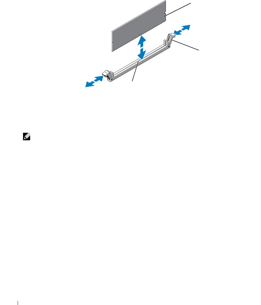
Figure 3-13. Installing and Removing a Memory Module
1
2
3
1 memory module 2 memory module socket
3 alignment key
ejectors (2)
6
Align the memory module's edge connector with the alignment key of the memory module socket, and
insert the memory module in the socket.
NOTE: The memory module socket has an alignment key that allows you to install the memory module in
the socket in only one way.
7
Press down on the memory module with your thumbs while pulling up on the ejectors with your index
fingers to lock the memory module into the socket.
When the memory module is properly seated in the socket, the ejectors on the memory module socket
align with the ejectors on the other sockets that have memory modules installed.
8
Repeat step 3 through step 7 of this procedure to install the remaining memory modules. See Table 3-1.
9
Replace the memory cooling shroud. See "Replacing the Memory Cooling Shroud" on page 53.
10
Close the system. See "Opening and Closing the System" on page 46.
11
Press <F2> to enter the System Setup program, and check the
System Memory
setting on the main
System Setup
screen.
The system should have already changed the value to reflect the newly installed memory.
12
If the value is incorrect, one or more of the memory modules may not be installed properly. Repeat step 1
through step 11 of this procedure, checking to ensure that the memory modules are firmly seated in their
sockets.
13
Run the system memory test in the system diagnostics. See "Running the System Diagnostics" on
page 111.
66 Installing System Components
Removing Memory Modules
CAUTION: Many repairs may only be done by a certified service technician. You should only perform
troubleshooting and simple repairs as authorized in your product documentation, or as directed by the online or
telephone service and support team. Damage due to servicing that is not authorized by Dell is not covered by your
warranty. Read and follow the safety instructions that came with the product.
CAUTION: The memory modules are hot to the touch for some time after the system has been powered down.
Allow time for the memory modules to cool before handling them. Handle the memory modules by the card edges
and avoid touching the components on the memory module.
1
Open the system. See "Opening and Closing the System" on page 46.
2
Remove the memory cooling shroud. See "Removing the Memory Cooling Shroud" on page 52.
3
Locate the memory module sockets. See Figure 6-2.
4
Press down and out on the ejectors on each end of the socket until the memory module pops out of the
socket. See Figure 3-13.
Handle each memory module only on either card edge, ensuring not to touch the middle of the memory
module.
5
Replace the memory cooling shroud. See "Replacing the Memory Cooling Shroud" on page 53.
6
Close the system. See "Opening and Closing the System" on page 46.
Activating the Integrated NIC TOE
To add TCP/IP Offload Engine (TOE) or iSCSI TOE functionality to the system's integrated NIC, install the
appropriate TOE or iSCSI TOE NIC hardware key in the TOE_KEY socket on the system board. S
ee
Figure 6-2.
Processors
You can upgrade your processor(s) to take advantage of future options in speed and functionality. Each
processor and its associated internal cache memory are contained in a land grid array (LGA) package that is
installed in a ZIF socket on the system board.
The following items are included in the processor upgrade kit:
• Processor
• Heat sink
Removing the Processor
CAUTION: Many repairs may only be done by a certified service technician. You should only perform
troubleshooting and simple repairs as authorized in your product documentation, or as directed by the online or
telephone service and support team. Damage due to servicing that is not authorized by Dell is not covered by your
warranty. Read and follow the safety instructions that came with the product.
1
Prior to upgrading your system, download the latest system BIOS version on
support.dell.com
.
Installing System Components 67
2
Turn off the system, including any attached peripherals, and disconnect the system from the electrical
outlet.
3
Open the system. See "Opening and Closing the System" on page 46.
4
Remove the memory cooling shroud. See "Removing the Memory Cooling Shroud" on page 52.
NOTICE: When you remove the heat sink, the possibility exists that the processor might adhere to the heat sink
and be removed from the socket. It is recommended that you remove the heat sink while the processor is warm.
NOTICE: Never remove the heat sink from a processor unless you intend to remove the processor. The heat sink
is necessary to maintain proper thermal conditions.
NOTICE: The processor and heat sink can become extremely hot. Be sure the processor has had sufficient time
to cool before handling.
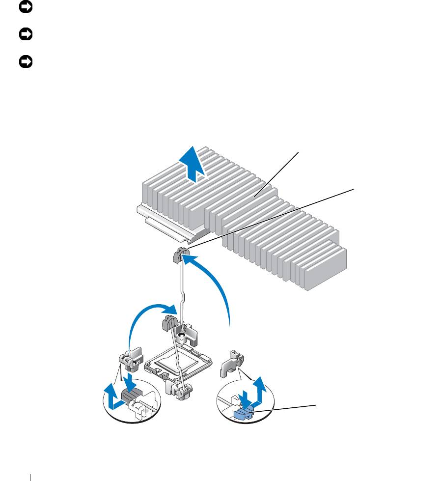
5
Press the blue tab on the end of one of the heat-sink retention levers to disengage the lever, then lift the
lever 90 degrees. See Figure 3-14.
Figure 3-14. Installing and Removing the Heat Sink
1
2
3
1 heat sink 2 heat-sink retention lever (2) 3 retention lever latch
68 Installing System Components
6
Wait 30 seconds for the heat sink to loosen from the processor.
7
Open the other heat sink retention lever.
8
If the heat sink has not separated from the processor, carefully rotate the heat sink in a clockwise, then
counterclockwise, direction until it releases from the processor. Do not pry the heat sink from the
processor.
9
Lift the heat sink off of the processor and set the heat sink upside down so as not to contaminate the
thermal grease.
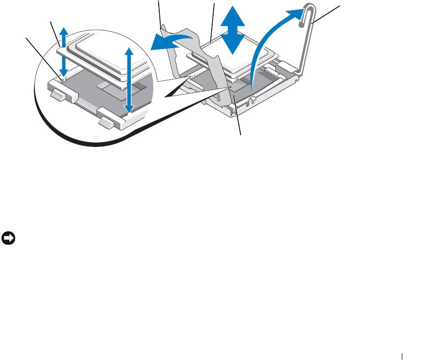
10
Pull the socket-release lever 90 degrees upward until the processor is released from the socket. See
Figure 3-15.
11
Rotate the processor shield upward and out of the way.
Figure 3-15. Installing and Removing the Processor
3
4
5
2
1
6
1 socket key (2) 2 notch in processor 3 processor shield
4 processor 5 socket-release lever 6 ZIF socket
12
Lift the processor shield to release the processor, and then lift the processor out of the socket. Leave the
release lever up so that the socket is ready for the new processor.
NOTICE: Be careful not to bend any of the pins on the LGA socket when removing the processor. Bending the
pins can permanently damage the socket and system board.
Installing System Components 69

Installing a Processor
1
Unpack the new processor.
2 Align the
p
rocessor with the
socket keys on t
he ZIF socket
. See Figure 3-15.
3
I
nstall the processor in the socket.
NOTICE: Positioning the processor incorrectly can permanently damage the system board or the processor when
you turn the system on.
a If the release lever on the processor socket is not positioned all the way up, move it to that position.
b With the
p
rocessor and
the
socket
keys
aligned, set the processor lightly in the socket.
NOTICE: Do not use force to seat the processor. When the processor is positioned correctly, it engages easily
into the socket.
c
W
hen the processor is fully seated in the socket, rotate the socket release lever back down until it
snaps into place, securing the processor.
See Figure 3-15.
d
Close the processor shield. See Figure 3-15.
4
Install the heat sink.
NOTE: If you did not receive a replacement heat sink, use the heat sink that you removed in step 9.
a
If you receive a heat sink and pre-applied thermal grease with your processor kit, remove the
protective sheet from the thermal grease layer on top of the heat sink.
If you did not receive a replacement heat sink with your processor kit, do the following:
• Using a clean lint-free cloth, remove the existing thermal grease from the heat sink you removed
in step 9.
• Open the grease packet included with your processor kit and apply thermal grease evenly to the
top of the processor.
b Place the heat sink onto the processor. See
Figure 3-14
.
c Close one of the two heat sink retention levers until it locks. See
Figure 3-14
.
d
Repeat for the other heat sink retention lever.
5
Close the system. See "Closing the System" on page 47.
As the system boots, it detects the presence of the new processor and automatically changes the system
configuration information in the System Setup program.
6
Press <F2> to enter the System Setup program, and check that the processor information
matches the new
system configuration.
See "Using the System Setup Program" on page 31 for instructions about using the System Setup program.
7
Run the system diagnostics to verify that the new processor operates correctly.
See "Running the System Diagnostics" on page 111 for information about running the diagnostics.
70 Installing System Components
RAC Card
CAUTION: Many repairs may only be done by a certified service technician. You should only perform
troubleshooting and simple repairs as authorized in your product documentation, or as directed by the online or
telephone service and support team. Damage due to servicing that is not authorized by Dell is not covered by your
warranty. Read and follow the safety instructions that came with the product.
The optional Remote Access Controller (RAC) provides a set of advanced features for managing the server
remotely. The following procedure describes the steps for installing or removing the optional RAC card.
Installing a RAC Card
1
Turn off the system, including any attached peripherals, and then disconnect the system from the electrical
outlet.
2
Open the system. See "Opening the System" on page 46
3
If applicable, remove the plastic filler plug from the system back panel. See Figure 3-16.
4
Remove any PCI cards attached to the center riser. See "Removing an Expansion Card" on page 62.
5
Remove the center riser card from the system board. See "Expansion-Card Riser" on page 82.
6
Angle the RAC card so that its NIC connector inserts through the back-panel RAC card opening, aligning
the card with the back standoff.
Figure 3-16. Installing and Removing a RAC Card
2
1
3
6
4
5
1 RAC card 2 RAC-card connectors (2) 3 filler plug location
4 back standoff 5 front standoffs (2) 6 RAC-card cable connectors
Installing System Components 71

7
Align the front edge of the RAC card with the front plastic retention standoffs, and then press down on the
front of the card until it is fully seated. See Figure 3-16.
When the front of the card is fully seated, the front plastic standoffs snap over the front edge of the card.
8
Connect the two small cables (44-pin cable and 50-pin cable), ensuring that connector labeled "Planar" is
attached to the appropriate system board connector and the connector labeled "DRAC" is attached to the
appropriate RAC card connector.
9
Replace the center riser card. See "Expansion-Card Riser" on page 82.
10
Replace any PCI cards that were removed from the center riser. See "Installing an Expansion Card" on
page 61.
11
Close the system. See "Closing the System" on page 47.
12
Reconnect the system and peripherals to their power sources, and then turn them on.
See the RAC card documentation for information on configuring and using the RAC card.
Removing the RAC Card and Cables
1
Turn off the system, including any attached peripherals, and then disconnect the system from the electrical
outlet.
2
Open the system. See "Opening the System" on page 46.
3
Remove any PCI cards attached to the center riser. See "Removing an Expansion Card" on page 62.
4
Remove the center riser card from the system board. See "Expansion-Card Riser" on page 82.
5
Remove the RAC card cables from the system board connectors by pressing the metal tabs inward and
then pulling up.
6
Remove the RAC card cables from the RAC connectors by pressing the metal tabs inward and then
pulling up.
7
Remove the RAC card by pressing outwardly on the front standoffs, and then lifting the RAC card up and
out of the system.
8
Replace the center riser card. See "Expansion-Card Riser" on page 82.
9
Replace any PCI cards that were removed from the center riser. See "Installing an Expansion Card" on
page 61.
10
Close the system. See "Closing the System" on page 47.
11
Reconnect the system and peripherals to their power sources, and then turn them on.
72 Installing System Components
Optical Drive
The optional slimline optical drive is mounted on a tray that slides into the front panel and connects to the
controllers on the system board through the sideplane board.
NOTE: DVD devices are data only.
Removing the Optical Drive Tray
CAUTION: Many repairs may only be done by a certified service technician. You should only perform
troubleshooting and simple repairs as authorized in your product documentation, or as directed by the online or
telephone service and support team. Damage due to servicing that is not authorized by Dell is not covered by your
warranty. Read and follow the safety instructions that came with the product.
1
Turn off the system, including any attached peripherals, and then disconnect the system from its electrical
outlet.
2
Remove the bezel. See "Removing and Replacing the Front Bezel" on page 45.
3
Open the system. See "Opening and Closing the System" on page 46.
4
Remove the SAS controller daughter card. See "Removing a SAS Controller Daughter Card" on page 56.
5
Disconnect the optical-drive cable from the back of the drive. See Figure 3-17.
6
To remove the optical drive, press forward on the blue tray release tab, and then slide the drive tray out of
the system. See Figure 3-17.
Installing System Components 73
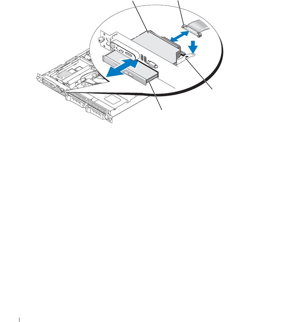
Figure 3-17. Removing and Installing the Optical Drive Tray
1
2
3
4
1 optical -drive tray 2 optical-drive cable 3 optical-drive release tab
4 optical drive
Installing the Optical Drive Tray
1
Align the optical drive tray with its opening in the front panel.
The optical drive opening is located directly below the SAS daughter card bay.
2
Slide in the drive tray until the tray snaps into place. See Figure 3-17.
3
Connect the optical-drive cable from the back of the drive. See Figure 3-17.
4
Replace the SAS controller daughter card.See "Installing a SAS Controller Daughter Card or SAS RAID
Controller Daughter Card" on page 56.
5
Close the system. See "Opening and Closing the System" on page 46.
6
Replace the bezel. See "Removing and Replacing the Front Bezel" on page 45.
7
Reconnect your system and peripherals to their electrical outlets, and turn on the system.
74 Installing System Components
Hard Drives
This subsection describes how to install and configure SAS or SATA hard drives in the system's internal
hard-drive bays.
Your system features the option of two 3.5-inch (SAS/SATA) internal hard-drive bays or four
2.5-inch (SAS only) internal hard-drive bays that accommodate up to either two or four hard drives. All drives
connect to the system board through one of two optional backplane boards.
NOTE: Depending on the hard drive configuration you ordered, your hard drive(s) may come with a drive
interposer that allows your SATA drive to attach to the SAS connector on the backplane.
Before You Begin
Hard drives are supplied in special hot-pluggable drive carriers that fit in the hard-drive bays. Depending on
your configuration, you received one of the following two drive carrier types:
• SATA drive carrier — Usable only with a SATA hard drive.
• SATAu drive carrier — Usable with either a SAS hard drive or a SATA hard drive with a universal
interposer card. The interposer card provides enhanced functionality that makes the SATA hard drive
usable in some storage systems.
NOTICE: Before you attempt to remove or install a drive while the system is running, see the documentation for
the optional SAS RAID daughter card to ensure that the host adapter is configured correctly to support hot-
pluggable drive removal and insertion.
NOTE: It is recommended that you use only drives that have been tested and approved for use with the SAS
backplane board.
You may need to use different programs than those provided with the operating system to partition and format
SAS or SATA hard drives.
NOTICE: Do not turn off or reboot your system while the drive is being formatted. Doing so can cause a drive
failure.
When you format a high-capacity hard drive, allow enough time for the formatting to be completed. Long
format times for these drives are normal. A 9-GB hard drive, for example, can take up to 2.5 hours to format.
Removing a Drive Blank
NOTICE: To maintain proper system cooling, all empty hard-drive bays must have drive blanks installed. If you
remove a hard-drive carrier from the system and do not reinstall it, you must replace the carrier with a drive blank.
The process for removing a drive blank depends on whether your system is configured with 3.5-inch or 2.5-
inch hard drives.
For 3.5-inch hard drive configurations:
1
Remove the front bezel, if attached. See "Removing and Replacing the Front Bezel" on page 45.
2
Insert your finger under the shrouded end of the blank and press in on the latch to eject the blank outward
from the bay.
3
Pry the ends of the blank outward until the blank is free.
Installing System Components 75

For 2.5-inch hard drive configurations, remove the blank as you would the 2.5-inch hard drive carrier:
1 Remove the front bezel, if attached. See
"Replacing the System Battery" on page 86
.
2 Open the drive blank release handle to release the blank. See
Figure 3-18
.
3
Slide the drive blank out until it is free of the drive bay.
Installing a Drive Blank
The process for installing a drive blank depends on whether your system is configured with 3.5-inch or 2.5-
inch hard drives.
For 3.5-inch hard drive configurations, the drive blank is keyed to ensure correct insertion into the drive bay.
To install a 3.5-inch drive blank, insert the blank into the drive bay rotating in with the key side first, and
press evenly on the ends of the blank until it is fully inserted and latched.
For 2.5-inch hard drive configurations, install the hard drive blank as a 2.5-inch hard drive carrier:
1 Remove the front bezel, if attached. See
"Removing and Replacing the Front Bezel" on page 45
.
2
Open the handle on the hard-drive blank.
3
Insert the hard-drive blank into the drive bay until it is fully seated.
4
Close the handle to lock the blank in place.
5 Replace the front bezel, if it was removed in
step 1.
Installing a Hot-Plug Hard Drive
NOTICE: When installing a hard drive, ensure that the adjacent drives are fully installed. Inserting a hard-drive
carrier and attempting to lock its handle next to a partially installed carrier can damage the partially installed
carrier's shield spring and make it unusable.
NOTICE: Not all operating systems support hot-plug drive installation. See the documentation supplied with
your operating system.
1
Remove the front bezel if attached. See "Removing and Replacing the Front Bezel" on page 45.
2
If a drive blank is present in the bay, remove it. See "Removing a Drive Blank" on page 75.
76 Installing System Components
3
Install the hot-plug hard drive.
a
Open the hard-drive carrier handle. See Figure 3-18.
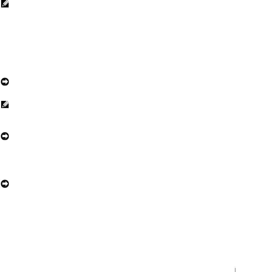
Figure 3-18. Installing a Hot-Plug Hard-Drive
3
2
1
1 drive carrier release handle 2 drive carrier 3 hard drive
NOTICE: Do not insert a hard-drive carrier and attempt to lock its handle next to a partially installed carrier.
Doing so can damage the partially installed carrier's shield spring and make it unusable. Ensure that the adjacent
drive carrier is fully installed.
b
Insert the hard-drive carrier into the drive bay until the carrier contacts the backplane. See
Figure 3-18.
c
Close the hard-drive carrier handle to lock it in place.
4
Replace the front bezel if it was removed in step 1. See "Removing and Replacing the Front Bezel" on
page 45.
Installing System Components 77

Replacing a Hard-Drive Carrier
Removing a Hard Drive From a Hard-Drive Carrier
1
If you are removing a SATA hard drive from a SATAu drive carrier, remove the interposer card:
a
Viewing the hard drive carrier from the rear, locate the release lever on the left end of the interposer
card.
b
Push the lever away from the carrier rail to release the left end of the card.
c
Rotate the left end away from the hard drive to release the connector.
d
Pull the right end of the interposer card clear of the slots in the carrier rail.
2
Remove the four screws from the slide rails on the hard-drive carrier and separate the hard drive from the
carrier.
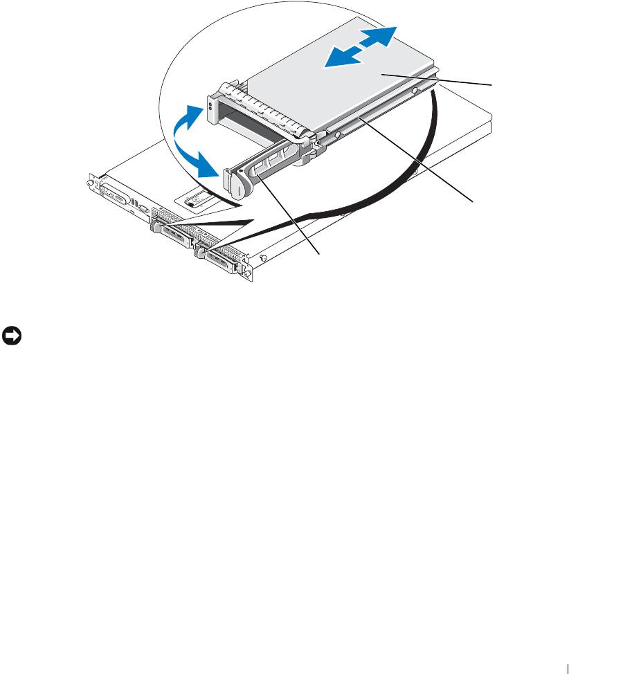
Installing a SAS Hard Drive Into a SATAu Drive Carrier
NOTE: SAS hard drives must be installed only in SATAu drive carriers. The SATAu drive carrier is labeled
"SATAu" and also has marks indicating the SAS and SATA mounting screws.
1 Insert the SAS hard drive into the hard-drive carrier with the connector end of the drive at the rear. See
Figure 3-19
.
2 Viewing the assembly as shown in
Figure 3-19, a
lign the bottom rear screw hole on the hard drive with
the hole labeled "SAS" on the hard drive carrier.
When aligned correctly, the rear of the hard drive will be flush with the rear of the hard-drive carrier.
3 Attach the four screws to secure the hard drive to the hard-drive carrier. See
Figure 3-19
.
78 Installing System Components
Figure 3-19. Installing a SAS Hard Drive Into a Drive Carrier
2
1
3
1 screws (4) 2 SATAu drive carrier 3 SAS hard drive
Installing a SATA Hard Drive Into a SATA Drive Carrier
NOTE: SATA hard drives that connect directly to the SAS backplane must be installed in SATA drive carriers
(labeled "SATA"). Only SATA hard drives with interposer cards can be installed in SATAu drive carriers.
1 Insert the SATA hard drive into the hard-drive carrier with the connector end of the drive at the rear.
See
Figure 3-20
.
2 Align the screw holes on the hard drive with the holes on the hard-drive carrier. See
Figure 3-20
.
3 Attach the four screws to secure the hard drive to the hard-drive carrier. See
Figure 3-20
.
Installing System Components 79
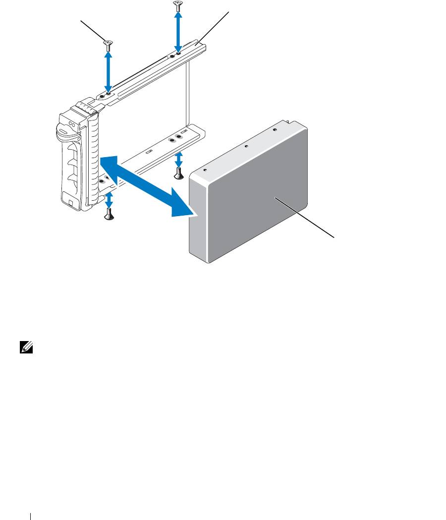
Figure 3-20. Installing a SATA Hard Drive Into a SATA Drive Carrier
2
1
3
1 screws (4) 2 SATA drive carrier 3 SATA hard drive
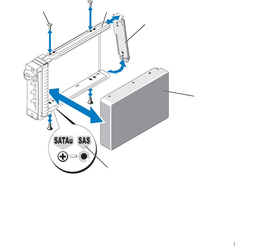
Installing a SATA Hard Drive and Interposer Card Into a SATAu Hard-Drive Carrier
NOTE: When you install a SATA hard drive into a SATAu drive carrier, you must install an interposer card onto
the back of the hard drive. The SATAu drive carrier is labeled "SATAu" and also has marks indicating the SAS and
SATA mounting screws.
1 Insert the SATA hard drive into the SATAu hard-drive carrier with the connector end of the drive at the
rear. See
Figure 3-21
.
2 Viewing the assembly as shown in
Figure 3-21, a
lign the bottom rear screw hole on the hard drive with
the hole labeled "SATAu" on the hard drive carrier.
When aligned correctly, the rear of the interposer will be flush with the rear of the hard-drive carrier.
3 Attach the four screws to secure the hard drive to the hard-drive carrier. See
Figure 3-21.
80 Installing System Components
4
Attach the interposer card to the rear of the SATA hard drive:
a
Angle the top of the interposer card into the inside top carrier rail so that the tabs on the interposer
card bracket attach to the slots on the inside of the carrier rail.
See
Figure 3-21.
b
Rotate the bottom end of the card toward the hard drive to seat the connector.
See
Figure 3-21.
c
Push the bottom end of the card towards the hard drive until the latch on the card bracket clicks into
place.
Figure 3-21. Installing a SATA Hard Drive and Interposer Card Into a SATAu Drive Carrier
1
2
3
4
5
1 screws (4) 2 SATAu drive carrier 3 interposer card (SATA only)
4 SATA hard-drive 5 hole labels
Installing System Components 81
Expansion-Card Riser
Removing an Expansion-Card Riser
CAUTION: Many repairs may only be done by a certified service technician. You should only perform
troubleshooting and simple repairs as authorized in your product documentation, or as directed by the online or
telephone service and support team. Damage due to servicing that is not authorized by Dell is not covered by your
warranty. Read and follow the safety instructions that came with the product.
1
If applicable, remove the bezel. See "Removing and Replacing the Front Bezel" on page 45.
2
Turn off the system and attached peripherals, and disconnect the system from the electrical outlet.
3
Open the system. See "Opening and Closing the System" on page 46.
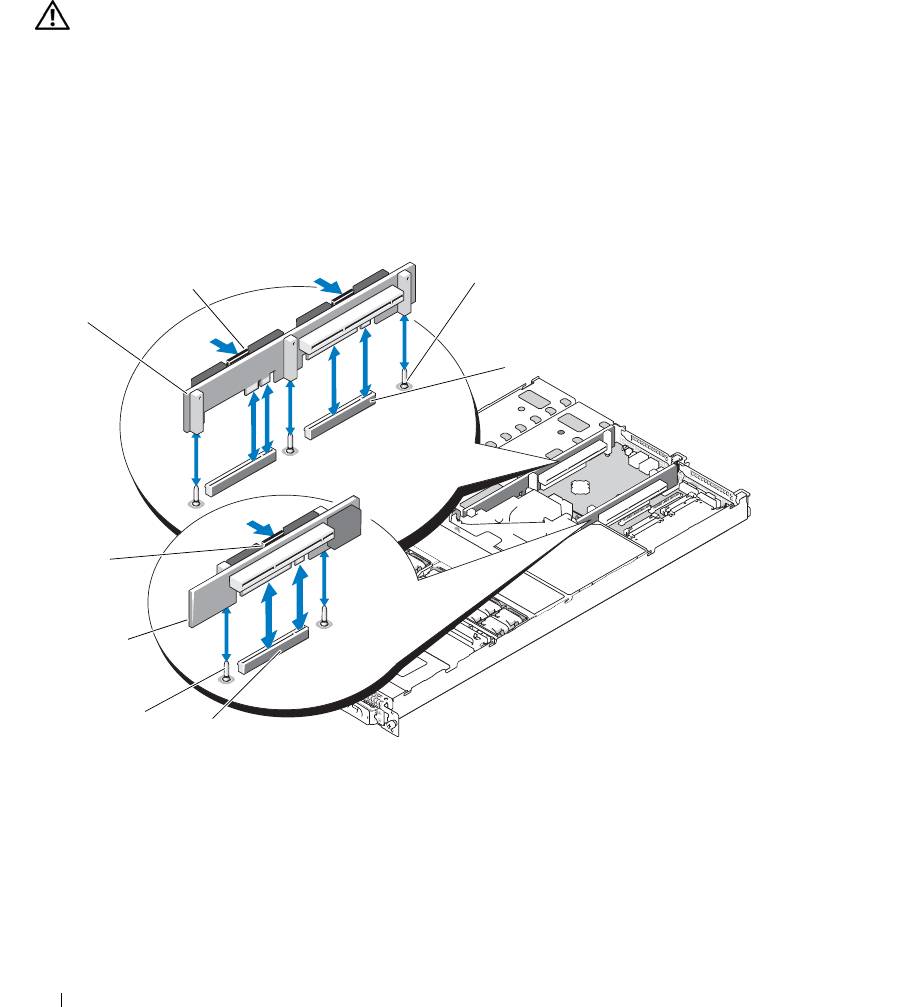
Figure 3-22. Expansion-Card Riser Removal
3
2
1
4
8
7
6
5
1 left riser board 2 left riser board release
3 left riser board alignment
latches (2)
pins (2)
4 left riser board connectors (2) 5 center riser board connector 6 center riser board alignment
pins (2)
7 center riser board 8 center riser board release latch
82 Installing System Components
4
If applicable, remove the expansion card from the riser.
5
Press the release latch(es) on the riser board and lift the riser board straight up from the system board. See
Figure 3-22.
The left riser board has two release latches; the center riser board has one latch.
Installing an Expansion-Card Riser
CAUTION: Many repairs may only be done by a certified service technician. You should only perform
troubleshooting and simple repairs as authorized in your product documentation, or as directed by the online or
telephone service and support team. Damage due to servicing that is not authorized by Dell is not covered by your
warranty. Read and follow the safety instructions that came with the product.
1
Align the riser board with the alignment pins on the system board, then lower the board onto the pins.
2
Press down on the riser board until the edge connector(s) on the board is (are) fully seated in the riser
board connector on the system board. See Figure 3-22.
3
If applicable, install the expansion card in the expansion-card slot.
4
Close the system. See "Opening and Closing the System" on page 46.
5
Replace the bezel. See "Removing and Replacing the Front Bezel" on page 45.
6
Reconnect your system and peripherals to their electrical outlets, and turn on the system.
Backplane Board
Removing the Backplane Board
CAUTION: Many repairs may only be done by a certified service technician. You should only perform
troubleshooting and simple repairs as authorized in your product documentation, or as directed by the online or
telephone service and support team. Damage due to servicing that is not authorized by Dell is not covered by your
warranty. Read and follow the safety instructions that came with the product.
The removal procedure varies slightly, depending on which backplane board you have in your system.
1
If applicable, remove the bezel. See "Removing and Replacing the Front Bezel" on page 45.
2
Turn off the system and attached peripherals, and disconnect the system from the electrical outlet.
3
Open the system. See "Opening and Closing the System" on page 46.
4
Remove the hard drives.
NOTICE: To properly reinstall the hard drives, ensure that you record which hard drive you remove from
which bay.
5
Disconnect the SAS cable and power cable from the backplane.
– If you are removing a 3.5-inch hard drive (two-drive) backplane, see Figure 3-23.
– If you are removing a 2.5-inch hard drive (four-drive) backplane, see Figure 6-4.
Installing System Components 83
6
Remove the backplane board:
– If you are removing a 3.5-inch hard drive (two-drive) backplane, press the release latch at the left end
of the board, slide the board to its right, and lift the backplane off of the securing tabs. See
Figure 3-23.
– If you are removing a 2.5-inch hard drive (four-drive) backplane, press the release latch at each end of
the backplane and lift the backplane off of the securing tabs. See Figure 6-4.
Figure 3-23. 2.5-Inch Hard Drive Backplane Board Removal and Installation
1
2
6
3
5
4
1 backplane board release latch 2 backplane board 3 securing slots
4 securing tabs 5 SAS interface cable 6 power cable
84 Installing System Components
Installing the Backplane Board
CAUTION: Many repairs may only be done by a certified service technician. You should only perform
troubleshooting and simple repairs as authorized in your product documentation, or as directed by the online or
telephone service and support team. Damage due to servicing that is not authorized by Dell is not covered by your
warranty. Read and follow the safety instructions that came with the product.
1
Replace the backplane board:
– If you are installing a 3.5-inch hard drive (two-drive) backplane, fit the board onto the securing tabs,
press the release latch at the left end of the board and slide the board to its left. See Figure 3-23.
– If you are installing a 2.5-inch hard drive (four-drive) backplane, fit the board onto the securing tabs
on the back of the drive cage and slide the board downwards until the release latch at each end of the
backplane clicks into place. See Figure 6-4.
2
Connect the SAS cable and power cable to the backplane connectors.
3
Reinstall the hard drives.
NOTE: Reinstall the hard drives in the same drive bays from which they were removed.
4
Close the system.
5
If applicable, replace the bezel.
Sideplane Board
Removing the Sideplane Board
CAUTION: Many repairs may only be done by a certified service technician. You should only perform
troubleshooting and simple repairs as authorized in your product documentation, or as directed by the online or
telephone service and support team. Damage due to servicing that is not authorized by Dell is not covered by your
warranty. Read and follow the safety instructions that came with the product.
1
If applicable, remove the bezel. See "Removing and Replacing the Front Bezel" on page 45.
2
Turn off the system and attached peripherals, and disconnect the system from the electrical outlet.
3
Open the system. See "Opening and Closing the System" on page 46.
4
Remove the SAS controller daughter card. See "Removing a SAS Controller Daughter Card" on page 56.
5
Disconnect the control panel cable and optical drive cable (if applicable) from the sideplane. See
Figure 6-8.
6
Press inward on the two sideplane release latches marked in blue and lift the sideplane up and away from
the system board.
Installing System Components 85
Installing the Sideplane Board
CAUTION: Many repairs may only be done by a certified service technician. You should only perform
troubleshooting and simple repairs as authorized in your product documentation, or as directed by the online or
telephone service and support team. Damage due to servicing that is not authorized by Dell is not covered by your
warranty. Read and follow the safety instructions that came with the product.
1
Align the guide on the end of the sideplane board with the pins on the system board, and lower the
sideplane until that the sideplane connector is fully seated into the connector on the system board.
2
Connect the control panel cable and optical drive cable (if applicable) to the sideplane. See Figure 6-8.
3
Replace the SAS controller daughter card. See "Installing a SAS Controller Daughter Card or SAS RAID
Controller Daughter Card" on page 56.
4
Close the system. See "Opening and Closing the System" on page 46.
5
Replace the bezel. See "Removing and Replacing the Front Bezel" on page 45.
6
Reconnect your system and peripherals to their electrical outlets, and turn on the system.
System Battery
The system battery is a 3.0-volt (V), coin-cell battery.
Replacing the System Battery
CAUTION: Many repairs may only be done by a certified service technician. You should only perform
troubleshooting and simple repairs as authorized in your product documentation, or as directed by the online or
telephone service and support team. Damage due to servicing that is not authorized by Dell is not covered by your
warranty. Read and follow the safety instructions that came with the product.
CAUTION: There is a danger of a new battery exploding if it is incorrectly installed. Replace the battery only
with the same or equivalent type recommended by the manufacturer. Discard used batteries according to the
manufacturer's instructions. See your System Information Guide for additional information.
1
Turn off the system, including any attached peripherals, and disconnect the system from the electrical
outlet.
2
Open the system. See "Opening and Closing the System" on page 46.
3
If an expansion card is installed in the left riser board, remove the card. See "Removing an Expansion
Card" on page 62.
4
Locate the battery socket. See Figure 3-24.
NOTICE: If you pry the battery out of its socket with a blunt object, be careful not to touch the system board with
the object. Ensure that the object is inserted between the battery and the socket before you attempt to pry out the
battery. Otherwise, you may damage the system board by prying off the socket or by breaking circuit traces on the
system board.
NOTICE: To avoid damage to the battery connector, you must firmly support the connector while installing or
removing a battery.
86 Installing System Components
5
Remove the system battery.
a
Support the battery connector by pressing down firmly on the positive side of the connector.
b
While supporting the battery connector, press the battery toward the positive side of the connector and
pry it up out of the securing tabs at the negative side of the connector.
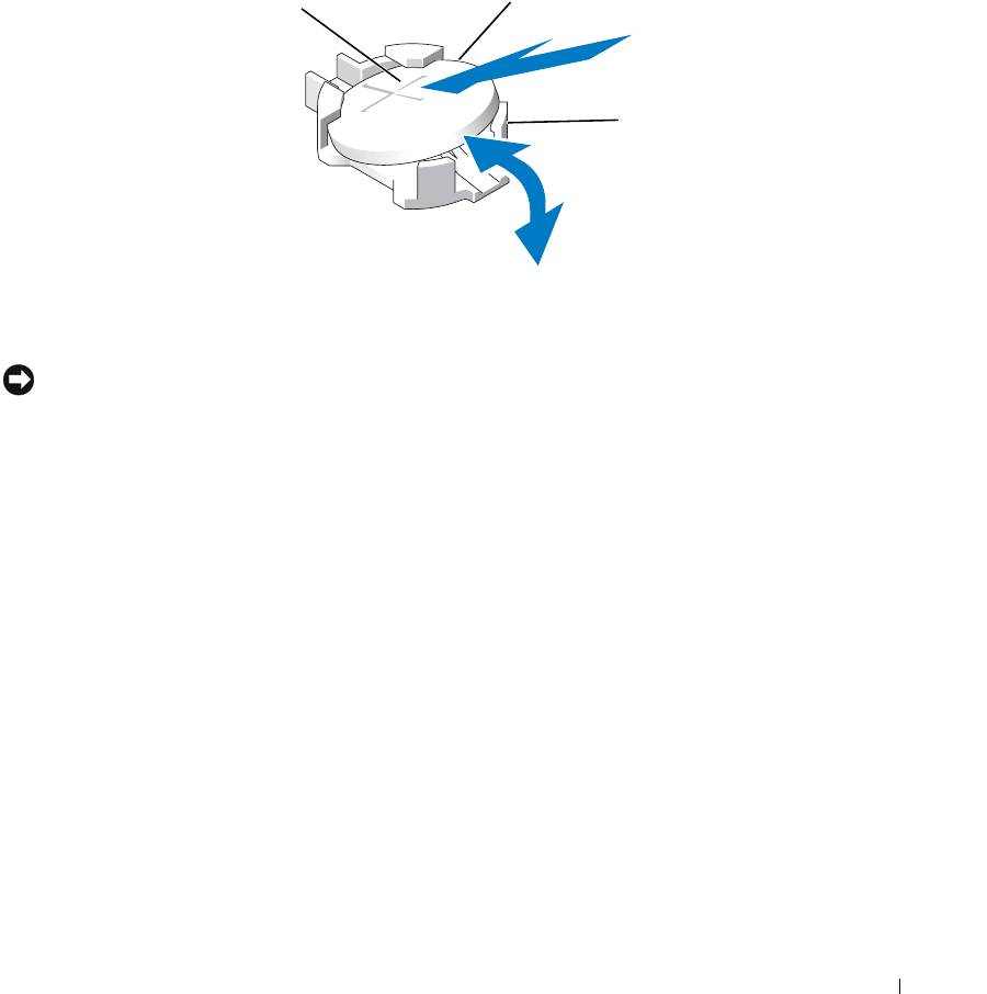
Figure 3-24. Replacing the System Battery
2
1
3
1 positive side of battery
2 system battery 3 negative side of battery
connector
connector
NOTICE: To avoid damage to the battery connector, you must firmly support the connector while installing or
removing a battery.
6
Install the new system battery.
a
Support the battery connector by pressing down firmly on the positive side of the connector.
b
Hold the battery with the "+" facing up, and slide it under the securing tabs at the positive side of the
connector.
c
Press the battery straight down into the connector until it snaps into place.
7
If you removed an expansion card in step 3, replace the card now. See "Installing an Expansion Card" on
page 61.
8
Close the system. See "Opening and Closing the System" on page 46.
9
Reconnect the system to its electrical outlet and turn the system on, including any attached peripherals.
10
Enter the System Setup program to confirm that the battery is operating properly. See "Using the System
Setup Program" on page 31.
11
Enter the correct time and date in the System Setup program's
Time
and
Date
fields.
12
Exit the System Setup program.
13
To test the newly installed battery, turn off the system and disconnect it from the electrical outlet for at
least an hour.
Installing System Components 87
14
After an hour, reconnect the system to its electrical outlet and turn it on.
15
Enter the System Setup program and if the time and date are still incorrect, see "Getting Help" on
page 125 for instructions on obtaining technical assistance.
Control Panel Assembly
Removing the Control Panel
CAUTION: Many repairs may only be done by a certified service technician. You should only perform
troubleshooting and simple repairs as authorized in your product documentation, or as directed by the online or
telephone service and support team. Damage due to servicing that is not authorized by Dell is not covered by your
warranty. Read and follow the safety instructions that came with the product.
1
If applicable, remove the bezel. See "Removing and Replacing the Front Bezel" on page 45.
2
Turn off the system and attached peripherals, and disconnect the system from the electrical outlet.
3
Open the system. See "Opening and Closing the System" on page 46.
4
Remove the SAS controller daughter card. See "Removing a SAS Controller Daughter Card" on page 56.
5
Disconnect the control panel cable at the back of the control panel board. See Figure 3-25.
NOTICE: Do not pull on the cable to unseat the connector. Doing so can damage the cable.
a
Squeeze the metal tabs on the ends of the cable connector.
b
Gently work the connector out of the socket.
6
Disconnect the front panel cable from the control panel board. See Figure 3-25.
7
Lift the release tab at the back of the control panel carrier and slide the carrier towards the back of the
system, then lift the carrier out of the system. See Figure 3-25.
8
Remove the three screws that secure the control panel board to the carrier and remove the board. See
Figure 3-25.
9
Remove the display module:
a
Insert the end of a paper clip into the hole on the right side of the display module and gently pry the
label off.
b
Using a T10 Torx driver, remove the two screws that secure the display module to the system chassis.
See Figure 3-25.
c
Remove the display module from the chassis cutout.
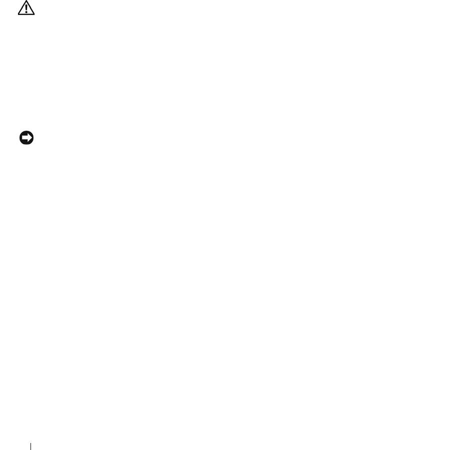
88 Installing System Components
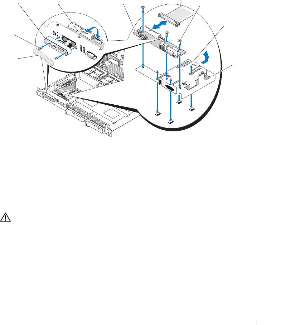
Figure 3-25. Control Panel Removal and Installation
4
1
2
3
5
6
9
8
7
1 display module 2 display module LCD cable 3 control panel circuit board
4 control panel cable 5 control-panel circuit board
6 control panel carrier release
securing screws (3)
tab
7 control panel carrier 8 display module label 9 display module securing
screws (2)
Installing the Control Panel
CAUTION: Many repairs may only be done by a certified service technician. You should only perform
troubleshooting and simple repairs as authorized in your product documentation, or as directed by the online or
telephone service and support team. Damage due to servicing that is not authorized by Dell is not covered by your
warranty. Read and follow the safety instructions that came with the product.
1
Insert the display module into the chassis cutout and secure it with the two screws.
2
Affix the control panel label to the display module.
3
Install the control panel board on the carrier, and secure it with the three Phillips screws. See Figure 3-25.
4
Install the carrier in the system chassis.
5
Connect the display module ribbon cable to the control panel board.
6
Connect the control panel ribbon cable to the control panel board.
Installing System Components 89
7
Replace the SAS controller daughter card. See "Installing a SAS Controller Daughter Card or SAS RAID
Controller Daughter Card" on page 56.
8
Close the system. See "Opening and Closing the System" on page 46.
9
Reconnect the system to the power source and turn on the system and attached peripherals.
10
If applicable, install the bezel. See "Removing and Replacing the Front Bezel" on page 45.
System Board
Removing the System Board
CAUTION: Many repairs may only be done by a certified service technician. You should only perform
troubleshooting and simple repairs as authorized in your product documentation, or as directed by the online or
telephone service and support team. Damage due to servicing that is not authorized by Dell is not covered by your
warranty. Read and follow the safety instructions that came with the product.
1
If applicable, remove the bezel. See "Removing and Replacing the Front Bezel" on page 45.
2
Turn off the system and attached peripherals, and disconnect the system from the electrical outlet.
3
Open the system. See "Opening and Closing the System" on page 46.
4
Disconnect any cables from the system board back panel.
5
Remove the memory cooling shroud. See "Removing the Memory Cooling Shroud" on page 52.
6
Remove both power supplies. See "Removing a Power Supply" on page 54.
7
Remove the sideplane from the system board. See "Removing the Sideplane Board" on page 85.
8
Remove both the center and left risers from the system board. See "Removing an Expansion-Card Riser"
on page 82.
9
Remove the four fan modules. See "Removing a Cooling Fan Module" on page 48.
10
If applicable, remove the RAC card. See "RAC Card" on page 71.
11
Remove the memory modules. See "Removing Memory Modules" on page 67.
CAUTION: The memory modules are hot to the touch for some time after the system has been powered down.
Allow time for the memory modules to cool before handling them. Handle the memory modules by the card edges
and avoid touching the components on the memory module.
NOTE: While removing the memory modules, record the memory module socket locations to ensure proper
installation.
NOTE: Your system also comes with a pre installed system board cooling shroud. Do not remove the
system board cooling shroud. See Figure 3-5.
12
Remove the heatsink(s) and microprocessor(s). See "Removing the Processor" on page 67.
13
If applicable, remove the TOE key. See "Activating the Integrated NIC TOE" on page 67.
90 Installing System Components
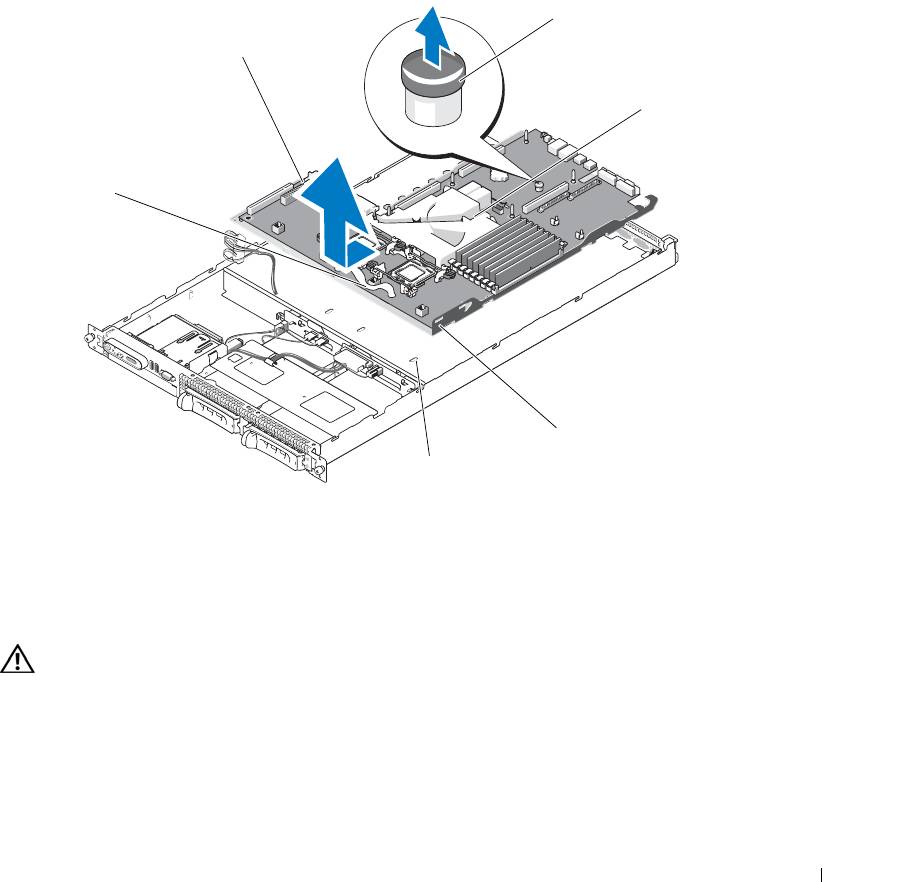
14
Remove the system board:
a
Pull the system-board release pin. See Figure 3-26.
b
While pulling the release pin, grasp the system board release handle and slide the system-board tray
toward the front of the chassis.
c
Lift up the system-board tray and remove it from the chassis.
Figure 3-26. System Board Removal
3
2
4
1
5
6
1 system-board tray release
2 system board attached to
3 system board release pin
handle
system-board tray
4 system board cooling shroud 5 system-board securing tabs 6 system-board securing slots
Installing the System Board
CAUTION: Many repairs may only be done by a certified service technician. You should only perform
troubleshooting and simple repairs as authorized in your product documentation, or as directed by the online or
telephone service and support team. Damage due to servicing that is not authorized by Dell is not covered by your
warranty. Read and follow the safety instructions that came with the product.
1
Lower the system-board tray until the tray sits flat on the bottom of the chassis.
2
Ensure that all system-board securing tabs are fully inserted into the system-board securing slots. See
Figure 3-26.
Installing System Components 91

3
Slide the system-board tray toward the back of the chassis until it locks into position.
4
If applicable, replace the RAC card. See "RAC Card" on page 71.
5
If applicable, replace the TOE key. See "Activating the Integrated NIC TOE" on page 67.
6
Replace the heatsink(s) and microprocessor(s).
7
Replace the memory modules. See "Installing Memory Modules" on page 65.
8
Replace both the center and left risers. See "Installing an Expansion-Card Riser" on page 83.
9
Replace any expansion card(s). See "Installing an Expansion Card" on page 61.
10
Replace the sideplane board. See "Installing the Sideplane Board" on page 86.
11
Replace the fan modules. See "Replacing a Cooling Fan Module" on page 49.
12
Replace the memory cooling shroud. See "Replacing the Memory Cooling Shroud" on page 53.
13
Replace the power supplies. See "Replacing a Power Supply" on page 55.
14
Connect any cables to the system.
15
Close the system. See "Opening and Closing the System" on page 46.
16
Replace the bezel. See "Removing and Replacing the Front Bezel" on page 45.
92 Installing System Components
