Dell PowerEdge 1950: Jumpers and Connectors
Jumpers and Connectors: Dell PowerEdge 1950

6
Jumpers and Connectors
This section provides specific information about the system jumpers. It also provides some basic
information on jumpers and switches and describes the connectors on the various boards in the system.
System Board Jumpers
Figure 6-1 shows the location of the configuration jumpers on the system board. Table 6-1 lists the
jumper settings.
NOTE: To access the jumpers, remove the system board cooling shroud by lifting the release latch and
sliding the shroud towards the front of the system. See Figure 3-13.
NOTE: Lift up the memory module airflow shroud for easy access to the jumpers.
Jumpers and Connectors 115
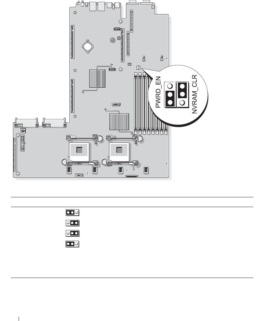
Figure 6-1. System Board Jumpers
Table 6-1. System Board Jumper Settings
Jumper Setting Description
1PWRD_EN
(default)
The password feature is enabled.
The password feature is disabled.
2NVRAM_CLR
(default)
The configuration settings are retained at system boot.
The configuration settings are cleared at the next system
boot. (If the configuration settings become corrupted to the
point where the system will not boot, install the jumper and
boot the system. Remove the jumper before restoring the
configuration information.)
NOTE: For the full name of an abbreviation or acronym used in this table, see the "Glossary" on page 147.
116 Jumpers and Connectors

Disabling a Forgotten Password
The system's software security features include a system password and a setup password, which are discussed in
detail in "Using the System Setup Program" on page 31. The password jumper enables these password features
or disables them and clears any password(s) currently in use.
NOTICE: See "Protecting Against Electrostatic Discharge" in the safety instructions in your Product Information
Guide.
1
Turn off the system, including any attached peripherals, and disconnect the system from the electrical
outlet.
2
Open the system. See "Opening and Closing the System" on page 46.
3
Lift up the memory module shroud.
4
Remove the jumper plug from the password jumper.
See Figure 6-1 to locate the password jumper on the system board.
5
Close the system.
6
Reconnect your system and peripherals to their electrical outlets, and turn on the system.
The existing passwords are not disabled (erased) until the system boots with the password jumper plug
removed. However, before you assign a new system and/or setup password, you must install the jumper
plug.
NOTE: If you assign a new system and/or setup password with the jumper plug still removed, the system
disables the new password(s) the next time it boots.
7
Turn off the system, including any attached peripherals, and disconnect the system from the electrical
outlet.
8
Open the system. See "Opening and Closing the System" on page 46.
9
Install the jumper plug on the password jumper.
10
Lower the memory module shroud.
11
Close the system.
12
Reconnect your system and peripherals to their electrical outlets, and turn on the system.
13
Assign a new system and/or setup password.
To assign a new password using the System Setup program, see "Assigning a System Password" on
page 38.
Jumpers and Connectors 117
System Board Connectors
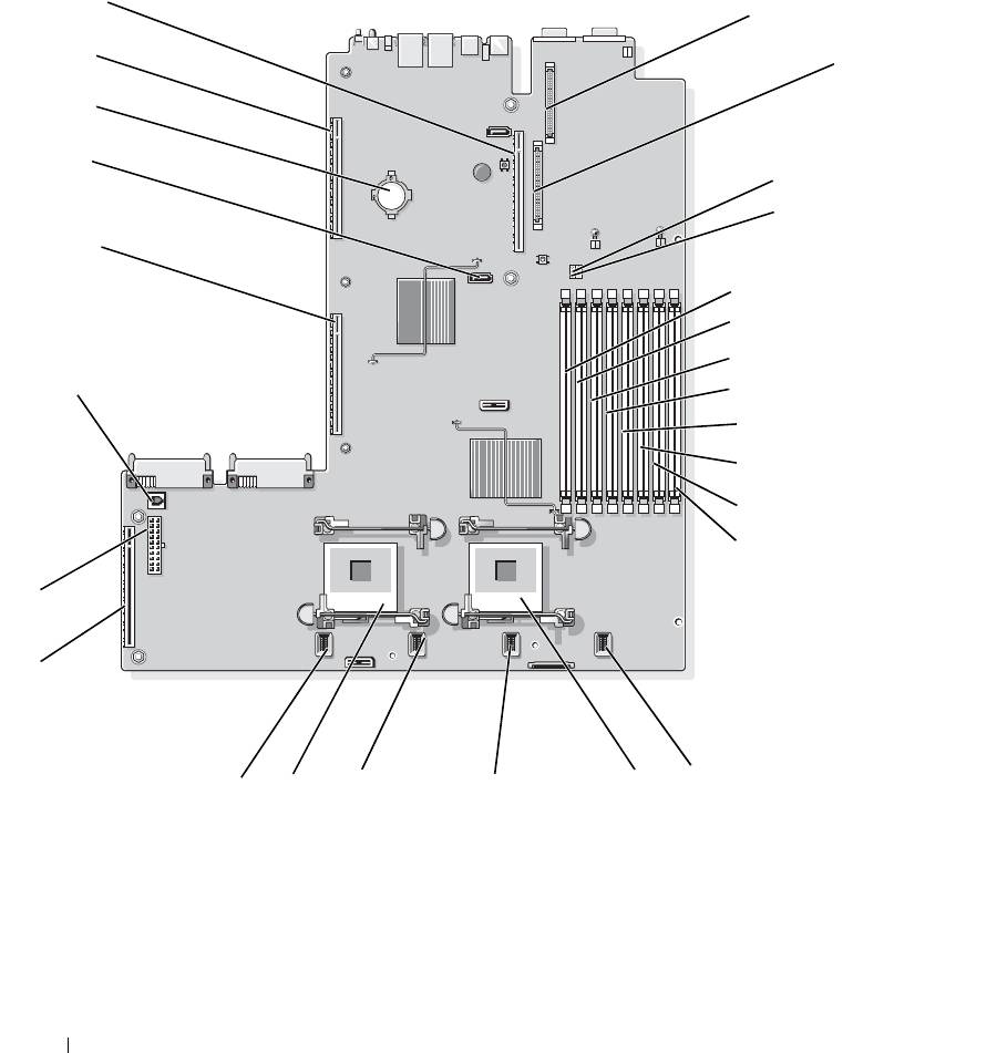
See Figure 6-2 and Table 6-2 for the location and description of system board connectors.
Figure 6-2. System Board Connectors
26
1
25
2
24
23
3
4
22
5
6
7
21
8
9
10
11
12
2
1
16
13
18
17
15
14
118 Jumpers and Connectors

Table 6-2. System Board Connectors
Connector Description
1 RAC_CONN2 Connector for the remote access control connector (RAC)
2 RAC_CONN1 Connector for the remote access control connector
3 NVRAM_CLR Configuration jumper
4 PWRD_EN Password jumper
5 DIMM 1 Memory module connector, slot 1
6 DIMM 5 Memory module connector, slot 5
7 DIMM 2 Memory module connector, slot 2
8 DIMM 6 Memory module connector, slot 6
9 DIMM 3 Memory module connector, slot 3
10 DIMM 7 Memory module connector, slot 7
11 DIMM 4 Memory module connector, slot 4
12 DIMM 8 Memory module connector, slot 8
13 FAN_MOD4 System cooling fan module 4 connector
14 CPU1 Microprocessor connector 1
15 FAN_MOD3 System cooling fan module 3 connector
16 FAN_MOD2 System cooling fan module 2 connector
17 CPU2 Microprocessor connector 2
18 FAN_MOD1 System cooling fan module 1 connector
19 SIDEPLANE Sideplane connector
20 BACKPLANE Backplane power connector
21 TOE_KEY TCP/IP offload engine key
22 LEFT PCIe RISER Left riser board connector
23 SATA_A SATA A connector
24 BATTERY Connector for the 3.0-V coin battery
25 LEFT PCI-X RISER Left riser board connector (PCIe or PCI-X)
26 CENTER RISER Center riser board connector (PCIe or PCI-X)
NOTE: For the full name of an abbreviation or acronym used in this table, see the "Glossary" on page 147.
Jumpers and Connectors 119
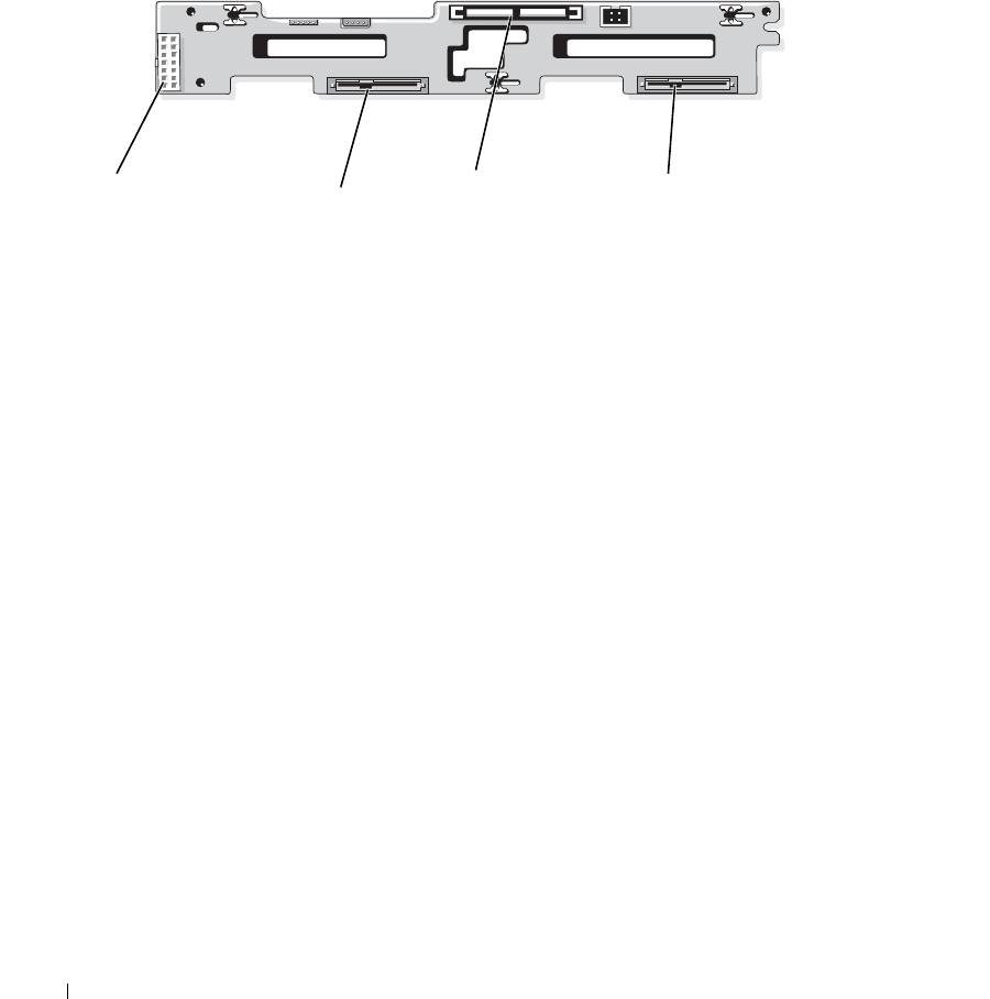
SAS/SATA Backplane Board Connectors
Figure 6-3 shows the location of the connectors on the SAS/SATA backplane board that supports two 3.5-inch
hard drives (Option 1).
Figure 6-3. SAS 3.5-Inch-Drive Backplane Board Components - Option 1
1
3
4
2
1 backplane power connector 2 Drive 0 connector 3 SAS A connector
4 Drive 1 connector
Figure 6-4 and Figure 6-5 show the location of the connectors on the SAS/SATA backplane board that supports
four 2.5-inch hard drives (Option 2).
120 Jumpers and Connectors
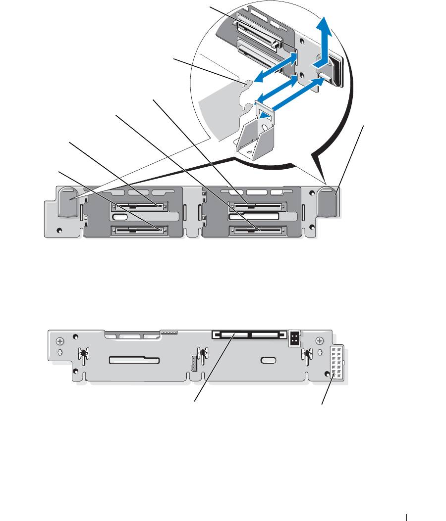
Figure 6-4. SAS 2.5-Inch-Drive Backplane Board Components - Option 2 (Front)
6
5
4
3
7
2
1
1 Drive 1 connector 2 Drive 0 connector 3 Drive 3 connector
4 Drive 2 connector 5 securing tabs 6 securing slots
7 release latches (2)
Figure 6-5. SAS Backplane Board Components - Option 2 (Back)
1
2
1 SAS A connector 2 backplane power connector
Jumpers and Connectors 121
Expansion-Card Riser-Board Components and PCI Buses
There are two expansion card configurations for this systems. Each riser (center riser and left riser) contains
one slot for either a PCI-X configuration or a PCIe configuration. This system supports only one
configuration (PCI-X or PCIe) for both risers. Figure 6-6 and Figure 6-7 show the components on the
optional PCI-X expansion-card riser boards, including the expansion-card slots and buses. "PCIe Riser
Board Expansion Slots" on page 61 and "PCI-X Riser Board Expansion Slots" on page 61 list the PCI bus
and operating speed for each expansion-card slot.
NOTE: Because the orientation and physical connectors are similar, the PCIe expansion card configuration is not
shown.
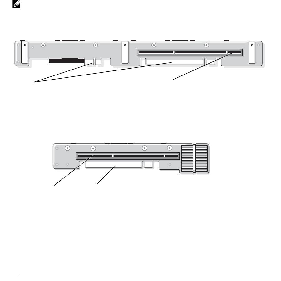
Figure 6-6. Optional PCI-X Expansion-Card Left Riser Board Components
2
1
1 connector to system board 2 slot 2 PCI-X 64 bit/133 MHz
Figure 6-7. Optional PCI-X Expansion-Card Center Riser Board Components
1
2
1 slot 1 PCI-X 2 connector to system board
122 Jumpers and Connectors
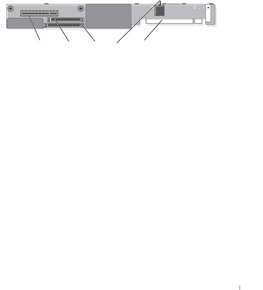
SAS Sideplane Board Connectors
Figure 6-8. Side Plane Components
15
2
3
4
1 SAS daughter card connector 2 control panel connector 3 IDE/optical drive connector
4 chassis intrusion switch 5 connector to system board
Jumpers and Connectors 123

124 Jumpers and Connectors
