Dell PowerEdge 1950: About Your System
About Your System: Dell PowerEdge 1950

1
About Your System
This section describes the physical, firmware, and software interface features that provide and ensure
the essential functioning of your system. The physical connectors on your system’s front and back
panels provide convenient connectivity and system expansion capability. The system firmware,
applications, and operating systems monitor the system and component status and alert you when a
problem arises. System conditions can be reported by any of the following:
• Front or back panel indicators
• LCD status messages
• System messages
• Warning messages
• Diagnostics messages
• Alert messages
This section describes each type of message, lists the possible causes, and provides steps to resolve any
problems indicated by a message. The system indicators and features are illustrated in this section.
Other Information You May Need
CAUTION: The Product Information Guide provides important safety and regulatory information.
Warranty information may be included within this document or as a separate document.
•The
Rack Installation Guide
or
Rack Installation Instructions
included with your rack solution
describes how to install your system into a rack.
•The
Getting Started Guide
provides an overview of system features, setting up your system, and
technical specifications.
• CDs included with your system provide documentation and tools for configuring and managing your
system.
• Systems management software documentation describes the features, requirements, installation, and
basic operation of the software.
• Operating system documentation describes how to install (if necessary), configure, and use the
operating system software.
• Documentation for any components you purchased separately provides information to configure and
install these options.
• Updates are sometimes included with the system to describe changes to the system, software, and/or
documentation.
About Your System 9

NOTE: Always check for updates on support.dell.com and read the updates first because they often
supersede information in other documents.
• Release notes or readme files may be included to provide last-minute updates to the system or
documentation or advanced technical reference material intended for experienced users or technicians.
Accessing System Features During Startup
Table 1-1 describes keystrokes that may be entered during startup to access system features. If your
operating system begins to load before you enter the keystroke, allow the system to finish booting, and then
restart your system and try again.
Table 1-1. Keystrokes for Accessing System Features
Keystroke Description
<F2> Enters the System Setup program. See "Using the System Setup Program" on page 31.
<F10> Enters the System Diagnostics program. See "Running the System Diagnostics" on page 112.
<Ctrl+E> Enters the Baseboard Management Controller (BMC) Management Utility, which allows access to the
system event log (SEL). See the BMC User’s Guide for more information on setup and use of BMC.
<Ctrl+C> Enters the SAS Configuration Utility. See your SAS adapter User’s Guide for more information.
<Ctrl+R> Enters the RAID configuration utility, which allows you to configure an optional RAID card. For more
information, see the documentation for your RAID card.
<Ctrl+S> Option is displayed only if you have PXE support enabled through the System Setup Program (see
"Integrated Devices Screen" on page 36). This keystroke allows you to configure NIC settings for PXE
boot. For more information, see the documentation for your integrated NIC.
<Ctrl+D> If you have the optional Dell Remote Access Controller (DRAC) installed, this keystroke allows
access to selected DRAC configuration settings. See the DRAC User’s Guide for more information on
setup and use of DRAC.
10 About Your System
Front-Panel Features and Indicators
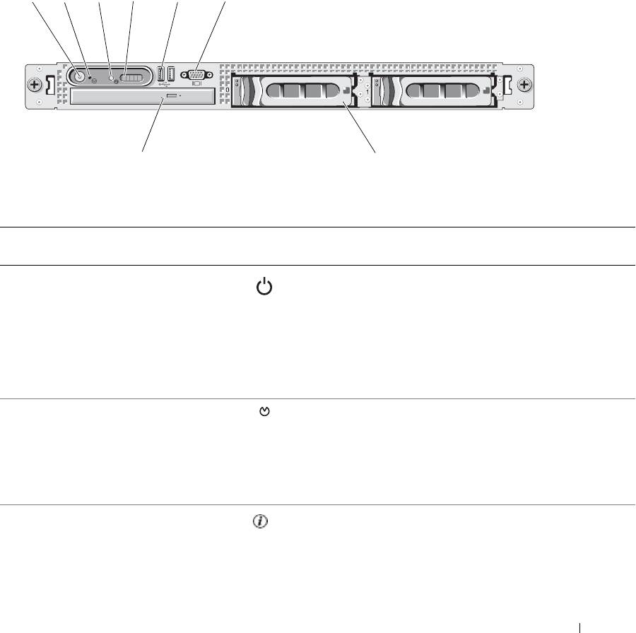
Figure 1-1 shows the controls, indicators, and connectors located behind the optional rack bezel on the
system's front panel.
Figure 1-1. Front-Panel Features and Indicators
21
6543
8
7
Table 1-2. Front-Panel LED Indicators, Buttons, and Connectors
Ite
Indicator, Button, or Connector Icon Description
m
1 Power-on indicator, power button The power button controls the DC power supply output to
the system.
NOTE: If you turn off the system using the power button
and the system is running an ACPI-compliant operating
system, the system performs a graceful shutdown before
the power is turned off. If the system is not running an
ACPI-compliant operating system, the power is turned off
immediately after the power button is pressed.
2 NMI button Used to troubleshoot software and device driver errors
when using certain operating systems. This button can be
pressed using the end of a paper clip.
Use this button only if directed to do so by qualified
support personnel or by the operating system's
documentation.
3 System identification button The identification buttons on the front and back panels can
be used to locate a particular system within a rack. When
one of these buttons is pushed, the blue system status
indicator on the front and back blinks until one of the
buttons is pushed again.
About Your System 11
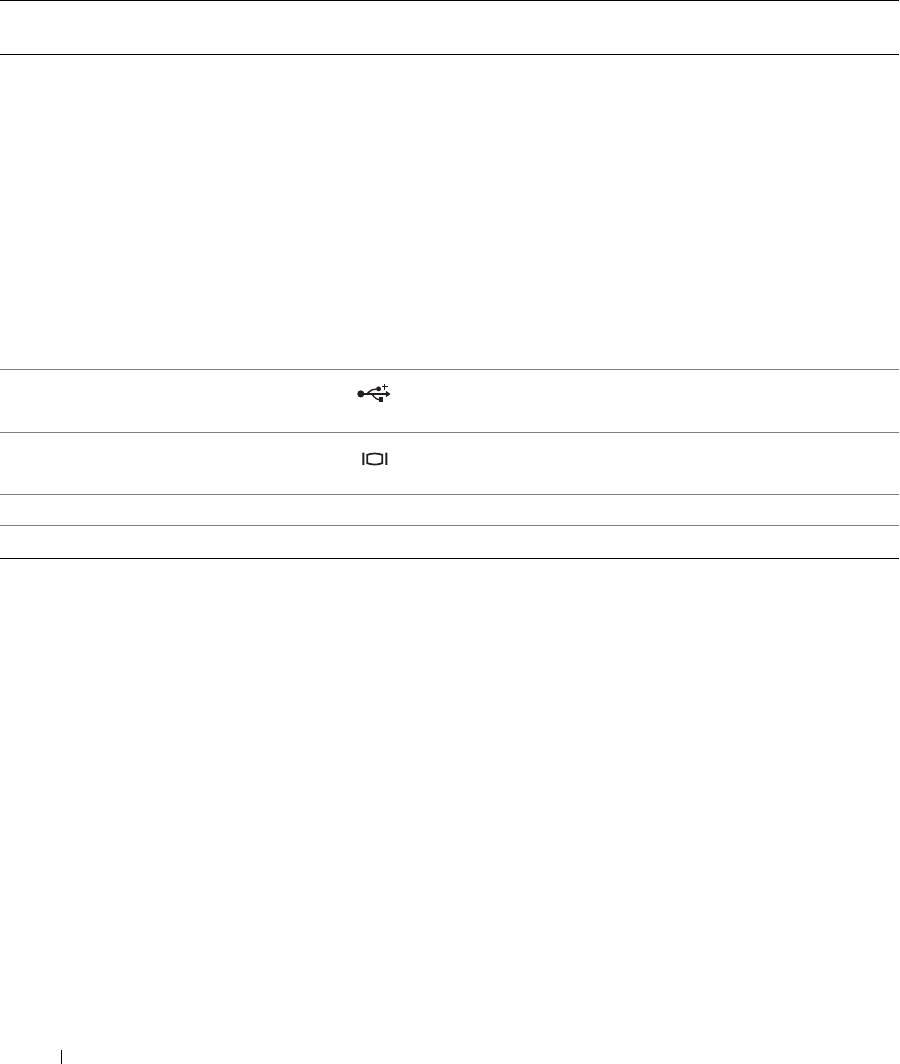
Table 1-2. Front-Panel LED Indicators, Buttons, and Connectors (continued)
Ite
Indicator, Button, or Connector Icon Description
m
4 LCD display Provides system ID, status information, and system error
messages.
The LCD display lights during normal system operation.
Both the systems management software and the
identification buttons located on the front and back of the
system can cause the LCD to flash blue to identify a
particular system.
The LCD display lights amber when the system needs
attention due to a problem with power supplies, fans,
system temperature, or hard drives.
NOTE: If the system is connected to AC power and an
error has been detected, the LCD display lights amber
regardless of whether the system has been powered on.
5 USB connectors (2) Connects USB 2.0-compliant devices to the system.
6 Video connector Connects a monitor to the system.
7 Hard drives (optional) Four 2.5" drives or two 3.5" drives (shown in figure).
8 Optical drive (optional) One optional slimline optical drive
NOTE: DVD devices are data only.
Hard-Drive Indicator Codes
If your hard drives are configured with the optional SAS RAID daughter card, two indicators on each of the
hard-drive carriers provide information on the status of the hard drives. See Figure 1-2 and Table 1-3. The
SAS backplane firmware controls the drive power-on/fault indicator.
12 About Your System
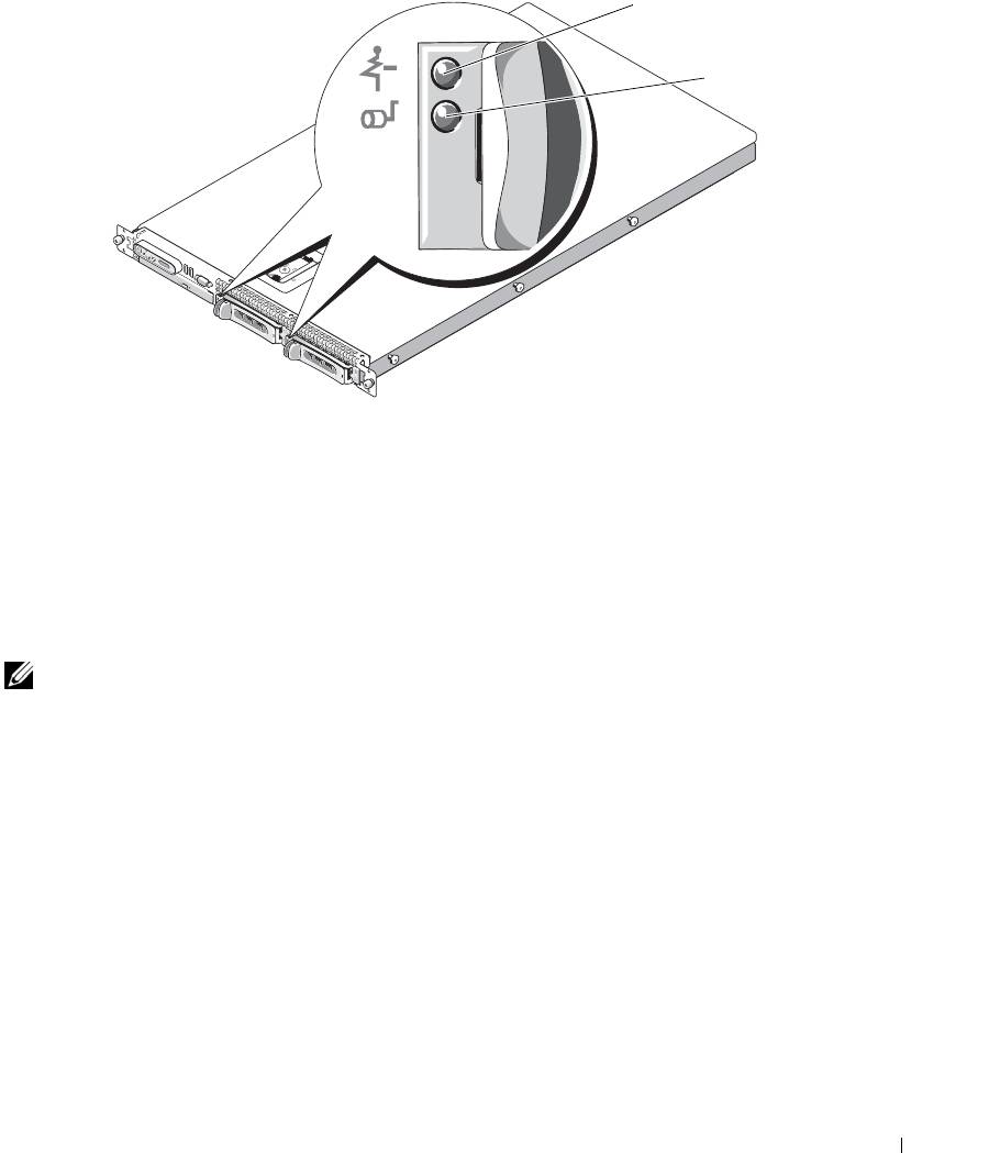
Figure 1-2. Hard-Drive Indicators
1
2
1 drive-status indicator (green
2 green drive-activity indicator
and amber)
Table 1-3 lists the drive indicator patterns. Different patterns are displayed as drive events occur in the
system. For example, if a hard-drive fails, the "drive failed" pattern appears. After the drive is selected for
removal, the "drive being prepared for removal" pattern appears, followed by the "drive ready for insertion
or removal" pattern. After the replacement drive is installed, the "drive being prepared for operation" pattern
appears, followed by the "drive online" pattern.
NOTE: For non-RAID configurations, only the drive-activity indicator is active. The drive-status indicator is off.
About Your System 13
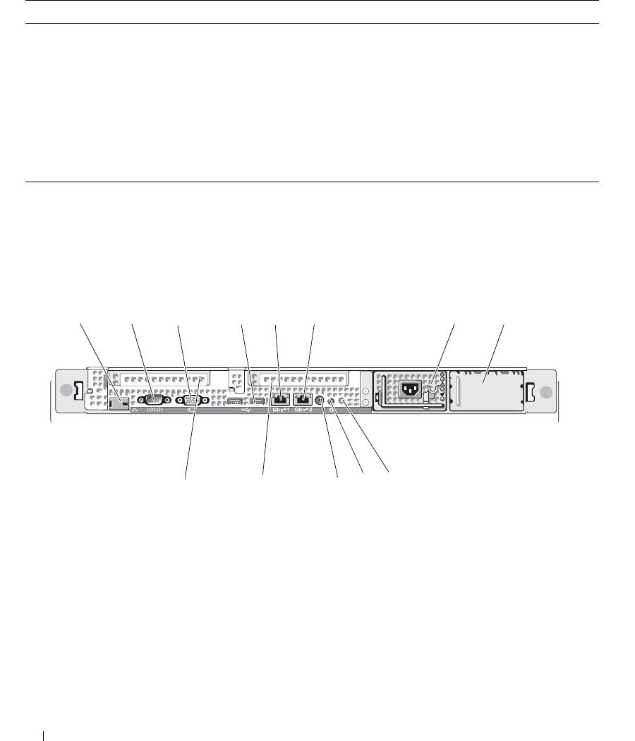
Table 1-3. Hard-Drive Indicator Patterns for RAID
Condition Drive-Status Indicator Pattern
Identify drive/preparing for removal Blinks green two times per second.
Drive ready for insertion or removal Off
Drive predicted failure Blinks green, amber, and off.
Drive failed Blinks amber four times per second.
Drive rebuilding Blinks green slowly.
Drive online Steady green.
Rebuild aborted Blinks green three seconds, amber three seconds, and off six seconds.
Back-Panel Features and Indicators
Figure 1-3 shows the controls, indicators, and connectors located on the system's back panel.
Figure 1-3. Back-Panel Features and Indicators
1 3
2
4
5
6
7
8
12
10
9
13
11
1 remote access controller
2 serial connector 3 video connector
(optional)
4 USB connectors (2) 5 NIC1 connector 6 NIC2 connector
7 power supply 1 8 power supply 2 (optional) 9 system status indicator
1
system identification button 11 system status indicator
12 left PCI expansion slot (slot 2)
0
connector
1
center PCI expansion slot
3
(slot 1)
14 About Your System
Connecting External Devices
When connecting external devices to your system, follow these guidelines:
• Most devices must be connected to a specific connector and device drivers must be installed before the
device operates properly. (Device drivers are normally included with your operating system software or
with the device itself.) See the documentation that accompanied the device for specific installation and
configuration instructions.
• Always attach external devices while your system is turned off. Next, turn on any external devices before
turning on the system (unless the documentation for the device specifies otherwise).
For information about individual connectors, see "Jumpers and Connectors" on page 115. For information about
enabling, disabling, and configuring I/O ports and connectors, see "Using the System Setup Program" on
page 31.
Power Indicator Codes
The power button on the front panel controls the power input to the system's power supplies. The power
indicator can provide information on power status (see
Figure 1-1
). Table 1-4 lists the power button indicator
codes.
Table 1-4. Power Button Indicators
Indicator Function
On Indicates that power is supplied to the system and the system is operational.
Off Indicates that no power is supplied to the system.
The indicators on the power supplies show whether power is present or whether a power fault has occurred
(see Figure 1-4).
Table 1-5. Power Supply Indicators
Indicator Function
Power supply status Green indicates that the power supply is operational.
Power supply fault Amber indicates a problem with the power supply.
AC line status Green indicates that a valid AC source is connected to the power supply.
About Your System 15
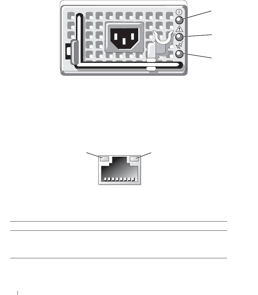
Figure 1-4. Power Supply Indicators
1
2
3
1 power supply status indicator 2 power supply fault indicator 3 AC line status indicator
NIC Indicator Codes
Each NIC on the back panel has an indicator that provides information on network activity and link status.
See Figure 1-5. Table 1-6 lists the NIC indicator codes.
Figure 1-5. NIC Indicators
1
2
1 link indicator 2 activity indicator
Table 1-6. NIC Indicator Codes
Indicator Indicator Code
Link and activity indicators are off The NIC is not connected to the network.
Link indicator is green The NIC is connected to a valid link partner on the network.
Activity indicator is amber blinking Network data is being sent or received.
16 About Your System
LCD Status Messages
The system's control panel LCD provides status messages to signify when the system is operating correctly
or when the system needs attention.
The LCD lights blue to indicate a normal operating condition, and lights amber to indicate an error
condition. The LCD scrolls a message that includes a status code followed by descriptive text. Table 1-7 lists
the LCD status messages that can occur and the probable cause for each message. The LCD messages refer
to events recorded in the System Event Log (SEL). For information on the SEL and configuring system
management settings, see the systems management software documentation.
CAUTION: Many repairs may only be done by a certified service technician. You should only perform
troubleshooting and simple repairs as authorized in your product documentation, or as directed by the online or
telephone service and support team. Damage due to servicing that is not authorized by Dell is not covered by your
warranty. Read and follow the safety instructions that came with the product.
NOTE: If your system fails to boot, press the System ID button for at least five seconds until an error code
appears on the LCD. Record the code, then see "Getting Help" on page 125.
Table 1-7. LCD Status Messages
Code Text Causes Corrective Actions
N/A SYSTEM NAME A 62-character string that can be
This message is for information
defined by the user in the System
only.
Setup program.
You can change the system string
The SYSTEM NAME displays
in the System Setup program. See
under the following conditions:
"Using the System Setup Program"
• The system is powered on.
on page 31.
• The power is off and active
POST errors are displayed.
E1000 FAILSAFE, Call
See "Getting Help" on page 125.
Support
E1114 Temp Ambient Ambient system temperature is out
See "Troubleshooting System
of acceptable range.
Cooling Problems" on page 101.
E1116 Temp Memory Memory has exceeded acceptable
See "Troubleshooting System
temperature and has been disabled
Cooling Problems" on page 101.
to prevent damage to the
components.
E12nn xx PwrGd Specified voltage regulator has
See "Getting Help" on page 125.
failed.
E1210 CMOS Batt CMOS battery is missing, or the
See "Troubleshooting the System
voltage is out of acceptable range.
Battery" on page 100.
About Your System 17

Table 1-7. LCD Status Messages (continued)
Code Text Causes Corrective Actions
E1211 ROMB Batt RAID battery is either missing,
Reseat the RAID battery
bad, or unable to recharge due to
connector. See "RAID Battery" on
thermal issues.
page 60, and "Troubleshooting
System Cooling Problems" on
page 101.
E1229 CPU # VCORE Processor # VCORE voltage
See "Getting Help" on page 125.
regulator has failed.
E1310 RPM Fan ## RPM of specified cooling fan is
See "Troubleshooting System
out of acceptable operating range.
Cooling Problems" on page 101.
E1311 RPM Fan Mod #x RPM of fan x in the # module is
See "Troubleshooting System
out of acceptable operating range.
Cooling Problems" on page 101.
E1313 Fan Redundancy The system is no longer fan-
Check control panel LCD for
redundant. Another fan failure will
additional scrolling messages. See
put the system at risk of over-
"Troubleshooting System Cooling
heating.
Problems" on page 101.
E1410 CPU # IERR Specified microprocessor is
See your system’s "Information
reporting an internal error.
Update Tech Sheet" located on
support.dell.com for the most
current system information. If the
problem persists, see "Getting
Help" on page 125.
E1414 CPU # Thermtrip Specified microprocessor is out of
See "Troubleshooting System
acceptable temperature range and
Cooling Problems" on page 101. If
has halted operation.
the problem persists, ensure that
the microprocessor heat sinks are
properly installed. See
"Troubleshooting the
Microprocessors" on page 108.
NOTE: The LCD continues to
display this message until the
system’s power cord is
disconnected and reconnected to
the AC power source, or the SEL
is cleared using either Server
Assistant or the BMC
Management Utility. See the Dell
OpenManage Baseboard
Management Controller User’s
Guide for information about these
utilities.
18 About Your System

Table 1-7. LCD Status Messages (continued)
Code Text Causes Corrective Actions
E1418 CPU # Presence Specified processor is missing or
See "Troubleshooting the
bad, and the system is in an
Microprocessors" on page 108.
unsupported configuration.
E141C CPU Mismatch Processors are in a configuration
See "System Memory" on page 63.
unsupported by Dell.
Ensure that your processors match
and conform to the type described
in the Microprocessor Technical
Specifications outlined in your
system’s Getting Started Guide.
E141F CPU Protocol The system BIOS has reported a
See "Getting Help" on page 125.
processor protocol error.
E1420 CPU Bus PERR The system BIOS has reported a
See "Getting Help" on page 125.
processor bus parity error.
E1421 CPU Init The system BIOS has reported a
See "Getting Help" on page 125.
processor initialization error.
E1422 CPU Machine Chk The system BIOS has reported a
See "Getting Help" on page 125.
machine check error.
E1610 PS # Missing No power is available from the
See "Troubleshooting Power
specified power supply; specified
Supplies" on page 100.
power supply is improperly
installed or faulty.
E1614 PS # Status No power is available from the
See "Troubleshooting Power
specified power supply; specified
Supplies" on page 100.
power supply is improperly
installed or faulty.
E1618 PS # Predictive Power supply voltage is out of
See "Troubleshooting Power
acceptable range; specified power
Supplies" on page 100.
supply is improperly installed or
faulty.
E161C PS # Input Lost Power source for specified power
Check the AC power source for the
supply is unavailable, or out of
specified power supply. If the
acceptable range.
problem persists, see
"Troubleshooting Power Supplies"
on page 100.
E1620 PS # Input Range Power source for specified power
Check the AC power source for the
supply is unavailable, or out of
specified power supply. If the
acceptable range.
problem persists, see
"Troubleshooting Power Supplies"
on page 100.
About Your System 19

Table 1-7. LCD Status Messages (continued)
Code Text Causes Corrective Actions
E1624 PS Redundancy The power supply subsystem is no
See "Troubleshooting Power
longer redundant. If the last supply
Supplies" on page 100.
fails, the system will go down.
E1710 I/O Channel Chk The system BIOS has reported an
See "Getting Help" on page 125.
I/O channel check.
E1711 PCI PERR B## D##
The system BIOS has reported a
Remove and reseat the PCI
F##
PCI parity error on a component
expansion cards. If the problem
that resides in PCI configuration
persists, see "Troubleshooting
space at bus ##, device ##,
Expansion Cards" on page 107.
function ##.
If the problem persists, the riser
PCI PERR Slot #
The system BIOS has reported a
card or system board is faulty. See
PCI parity error on a component
"Getting Help" on page 125.
that resides in the specified PCI
slot.
E1712 PCI SERR B## D##
The system BIOS has reported a
Remove and reseat the PCI
F##
PCI system error on a component
expansion cards. If the problem
that resides in PCI configuration
persists, see "Getting Help" on
space at bus ##, device ##,
page 125.
function ##.
If the problem persists, the riser
PCI SERR Slot #
The system BIOS has reported a
card or system board is faulty. See
PCI system error on a component
"Getting Help" on page 125.
that resides in the specified slot.
E1714 Unknown Err The system BIOS has determined
See "Getting Help" on page 125.
that there has been an error in the
system, but is unable to determine
its origin.
E171F PCIE Fatal Err
The system BIOS has reported a
Remove and reseat the PCI
B## D## F##
PCIe fatal error on a component
expansion cards. If the problem
that resides in PCI configuration
persists, see "Troubleshooting
space at bus ##, device ##,
Expansion Cards" on page 107.
function ##.
If the problem persists, the riser
PCIE Fatal Err
The system BIOS has reported a
card or system board is faulty. See
Slot #
PCIe fatal error on a component
"Getting Help" on page 125.
that resides in the specified slot.
E1810 HDD ## Fault The SAS subsystem has
See "Troubleshooting a Hard
determined that hard drive ## has
Drive" on page 104.
experienced a fault.
20 About Your System

Table 1-7. LCD Status Messages (continued)
Code Text Causes Corrective Actions
E1811 HDD ## Rbld Abrt The specified hard drive has
See "Troubleshooting a Hard
experienced a rebuild abort.
Drive" on page 104. If the problem
persists, see your RAID
documentation.
E1812 HDD ## Removed The specified hard drive has been
Information only.
removed from the system.
E1913 CPU & Firmware
The BMC firmware does not
Update to the latest BMC
Mismatch
support the CPU.
firmware. See the BMC User’s
Guide for more information on
setup and use of BMC.
E1A14 SAS Cable A SAS cable A is missing or bad. Reseat the cable. If the problem
persists, replace the cable. See
"SAS Controller Daughter Card"
on page 56.
E1A15 SAS Cable B SAS cable B is missing or bad. Reseat the cable. If the problem
persists, replace the cable. See
"SAS Controller Daughter Card"
on page 56.
E1A17 Pwr Cable FB Flex bay power cable is missing or
Reseat the cable. If the problem
bad.
persists, replace the cable. See
"SAS Controller Daughter Card"
on page 56.
E1A18 PDB Ctrl Cable Flex bay control signals cable is
Reseat the cable. If the problem
missing or bad.
persists, replace the cable. See
"SAS Controller Daughter Card"
on page 56.
E2010 No Memory No memory is installed in the
Install memory. See "Installing
system.
Memory Modules" on page 65.
E2011 Mem Config Err Memory detected, but is not
See "Troubleshooting System
configurable. Error detected
Memory" on page 102.
during memory configuration.
E2012 Unusable Memory Memory is configured, but not
See "Troubleshooting System
usable. Memory subsystem failure.
Memory" on page 102.
E2013 Shadow BIOS Fail The system BIOS failed to copy its
See "Troubleshooting System
flash image into memory.
Memory" on page 102.
E2014 CMOS Fail CMOS failure. CMOS RAM not
See "Getting Help" on page 125.
functioning properly.
E2015 DMA Controller DMA controller failure. See "Getting Help" on page 125.
About Your System 21

Table 1-7. LCD Status Messages (continued)
Code Text Causes Corrective Actions
E2016 Int Controller Interrupt controller failure. See "Getting Help" on page 125.
E2017 Timer Fail Timer refresh failure. See "Getting Help" on page 125.
E2018 Prog Timer Programmable interval timer error. See "Getting Help" on page 125.
E2019 Parity Error Parity error. See "Getting Help" on page 125.
E201A SIO Err SIO failure. See "Getting Help" on page 125.
E201B Kybd Controller Keyboard controller failure. See "Getting Help" on page 125.
E201C SMI Init System management interrupt
See "Getting Help" on page 125.
(SMI) initialization failure.
E201D Shutdown Test BIOS shutdown test failure. See "Getting Help" on page 125.
E201E POST Mem Test BIOS POST memory test failure. See "Troubleshooting System
Memory" on page 102. If the
problem persists, see "Getting
Help" on page 125.
E201F DRAC Config Dell remote access controller
Check for specific error messages.
(DRAC) configuration failure.
Ensure that DRAC cables and
connectors are properly seated. If
the problem persists, see your
DRAC documentation.
E2020 CPU Config CPU configuration failure. Check for specific error messages.
E2021 Memory
Incorrect memory configuration.
Check for specific error messages.
Population
Memory population order
See "Troubleshooting System
incorrect.
Memory" on page 102.
E2022 POST Fail General failure after video. Check for specific error messages.
E2110 MBE Crd # DIMM ##
One of the DIMMs in the set
See "Troubleshooting System
& ##
implicated by "## & ##" has had a
Memory" on page 102.
memory multi-bit error (MBE). If
no memory card is present, the
"Crd #" string is left out of the
message.
22 About Your System

Table 1-7. LCD Status Messages (continued)
Code Text Causes Corrective Actions
E2111 SBE Log Disable
The system BIOS has disabled
See "Troubleshooting System
Crd # DIMM ##
memory single-bit error (SBE)
Memory" on page 102.
logging, and will not resume
logging further SBEs until the
system is rebooted. "##" represents
the DIMM implicated by the
BIOS. If no memory riser card is
present, the "Crd #" string is left
out of the message.
E2112 Mem Spare Crd #
The system BIOS has spared the
See "Troubleshooting System
DIMM ##
memory because it has determined
Memory" on page 102.
that the memory had too many
errors. "## & ##" represents the
DIMM pair implicated by the
BIOS. If no memory card is
present, the "Crd #" string is left
out of the message.
E2113 Mem Mirror Crd #
The system BIOS has disabled
See "Troubleshooting System
DIMM ## & ##
memory mirroring because it has
Memory" on page 102.
determined that one half of the
mirror has had too many errors.
"## & ##" represents the DIMM
pair implicated by the BIOS. If no
memory card is present, the "Crd
#" string is left out of the message.
E2118 Fatal NB Mem CRC One of the connections in the FBD
See "Troubleshooting System
memory subsystem link on the
Memory" on page 102.
Northbound side has failed.
E2119 Fatal SB Mem CRC One of the connections in the FBD
See "Troubleshooting System
memory subsystem link on the
Memory" on page 102.
Southbound side has failed.
I1910 Intrusion System cover has been removed. Information only.
I1911 >3 ERRs Chk Log LCD overflow message.
Check the SEL for details on the
events.
A maximum of three error
messages can display sequentially
on the LCD. The fourth message
displays as the standard overflow
message.
About Your System 23

Table 1-7. LCD Status Messages (continued)
Code Text Causes Corrective Actions
I1912 SEL Full System Event Log is full of events,
Clear the log by deleting event
and is unable to log any more
entries.
events.
W1228 ROMB Batt < 24hr Warns predictively that the RAID
Replace RAID battery. See "RAID
battery has less than 24 hours of
Battery" on page 60.
charge left.
NOTE: For the full name of an abbreviation or acronym used in this table, see the "Glossary" on page 147.
Solving Problems Described by LCD Status Messages
The code and text on the LCD can often specify a very precise fault condition that is easily corrected. For
example, if the code E1418 CPU_1_Presence appears, you know that a microprocessor is not
installed in socket 1.
In contrast, you might be able to determine the problem if multiple related errors occur. For example, if you
receive a series of messages indicating multiple voltage faults, you might determine that the problem is a
failing power supply.
Removing LCD Status Messages
For faults associated with sensors, such as temperature, voltage, fans, and so on, the LCD message is
automatically removed when that sensor returns to a normal state. For example, if temperature for a
component goes out of range, the LCD displays the fault; when the temperature returns to the acceptable
range, the message is removed from the LCD. For other faults, you must take action to remove the message
from the display:
• Clear the SEL — You can perform this task remotely, but you will lose the event history for the system.
• Power cycle — Turn off the system and disconnect it from the electrical outlet; wait approximately ten
seconds, reconnect the power cable, and restart the system.
Any of these actions will remove fault messages, and return the status indicators and LCD colors to the
normal state. Messages will reappear under the following conditions:
• The sensor returns to a normal state but fails again, resulting in a new SEL entry.
• The system is reset and new error events are detected.
• A failure is recorded from another source that maps to the same display entry.
24 About Your System
System Messages
System messages appear on the screen to notify you of a possible problem with the system. Table 1-8 lists
the system messages that can occur and the probable cause and corrective action for each message.
NOTE: If you receive a system message that is not listed in Table 1-8, check the documentation for the
application that is running when the message appears or the operating system's documentation for an explanation
of the message and recommended action.
CAUTION: Many repairs may only be done by a certified service technician. You should only perform
troubleshooting and simple repairs as authorized in your product documentation, or as directed by the online or
telephone service and support team. Damage due to servicing that is not authorized by Dell is not covered by your
warranty. Read and follow the safety instructions that came with the product.
Table 1-8. System Messages
Message Causes Corrective Actions
Alert! Redundant memory
Installed memory modules are not the
Ensure that all memory modules are of the
disabled! Memory
same type and size; faulty memory
same type and size and that they are
configuration does not
module(s).
properly installed. If the problem persists,
support redundant memory.
see "Troubleshooting System Memory"
on page 102.
Attempting to update
Remote Configuration request has been
Wait until the process is complete.
Remote Configuration.
detected and is being processed.
Please wait...
BIOS Update Attempt
Remote BIOS update attempt failed. Retry the BIOS update. If the problem
Failed!
persists, see "Getting Help" on page 125.
Caution! NVRAM_CLR jumper
NVRAM_CLR jumper is installed.
Remove NVRAM_CLR jumper. See
is installed on system
CMOS has been cleared.
Figure 6-1 for jumper location.
board.
CPUs with different cache
Microprocessors with different cache
Ensure that all microprocessors have the
sizes detected!
sizes are installed.
same cache size and that they are properly
installed. See "Processors" on page 67.
Decreasing available
Faulty or improperly installed memory
See "Troubleshooting System Memory"
memory
modules.
on page 102.
DIMM pairs must be matched
Mismatched or unmatched DIMMs
Ensure that all pairs of memory modules
in size, speed, and
installed; faulty or improperly seated
are of the same type and size and that they
technology. The following
memory module(s).
are properly installed. See "System
DIMM pair is mismatched:
Memory" on page 63. If the problem
DIMM x and DIMM y.
persists, see "Troubleshooting System
Memory" on page 102.
About Your System 25

Table 1-8. System Messages (continued)
Message Causes Corrective Actions
DIMMs must be populated in
The specified DIMM is inaccessible to
Populate 2, 4, 8, or 12 DIMMs
sequential order beginning
the system due to its location. DIMMs
sequentially beginning with slot 1. See
with slot 1. The following
must be populated in sequential order,
"System Memory" on page 63.
DIMM is electrically
beginning with slot 1.
isolated: DIMM x.
DIMMs should be installed
Mismatched or unmatched DIMMs
Ensure that all pairs of memory modules
in pairs. Pairs must be
installed; faulty or improperly seated
are of the same type and size and that they
matched in size, speed,
memory module(s). The system will
are properly installed. See "System
and technology.
operate in a degraded mode with
Memory" on page 63. If the problem
reduced ECC protection. Only memory
persists, see "Troubleshooting System
installed in channel 0 will be
Memory" on page 102.
accessible.
Dual-rank DIMM paired with
Mismatched DIMMs installed; faulty
Ensure that all pairs of memory modules
Single-rank DIMM - The
memory module(s). The system has
are of the same type and size and that they
following DIMM/rank has
detected a dual-rank DIMM paired with
are properly installed. See "System
been disabled by BIOS:
a single-rank DIMM. The second rank
Memory" on page 63. If the problem
DIMM x Rank y
of the dual-rank DIMM will be
persists, see "Troubleshooting System
disabled.
Memory" on page 102.
Error: Incorrect memory
Mismatched or unmatched DIMMs
Ensure that all pairs of memory modules
configuration. DIMMs must
installed; faulty or improperly seated
are of the same type and size and that they
be installed in pairs of
memory module(s).
are properly installed. See "System
matched memory size,
Memory" on page 63. If the problem
speed, and technology.
persists, see "Troubleshooting System
Memory" on page 102.
Error: Memory failure
Faulty or improperly seated memory
See "Troubleshooting System Memory"
detected. Memory size
module(s).
on page 102.
reduced. Replace the
faulty DIMM as soon as
possible.
!!*** Error: Remote Access
Remote Access Controller initialization
Ensure that the Remote Access Controller
Controller initialization
failure.
is properly installed. See "RAC Card" on
failure*** RAC virtual USB
page 71.
devices may not be
available...
FBD training error: The
The specified branch (channel pair)
Ensure that only Dell-qualified memory is
following branch has been
contains DIMMs that are incompatible
used. Dell recommends purchasing
disabled: Branch x
with each other.
memory upgrade kits directly from
www.dell.com or your Dell sales agent to
ensure compatibility.
Gate A20 failure Faulty keyboard controller; faulty
See "Getting Help" on page 125.
system board.
26 About Your System
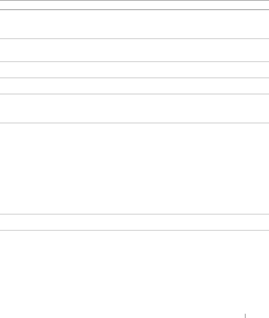
Table 1-8. System Messages (continued)
Message Causes Corrective Actions
General failure The operating system is unable to carry
This message is usually followed by
out the command.
specific information. Note the
information, and take the appropriate
action to resolve the problem.
Invalid NVRAM
System detected and corrected a
No action is required.
configuration, Resource
resource conflict.
Re-allocated
Keyboard Controller
Faulty keyboard controller; faulty
See "Getting Help" on page 125.
failure
system board
Manufacturing mode
System is in manufacturing mode. Reboot to take the system out of
detected
manufacturing mode.
MEMBIST failure - The
Faulty memory module(s). See "Troubleshooting System Memory"
following DIMM/rank has
on page 102.
been disabled by BIOS:
DIMM x Rank y
Memory address line
Faulty or improperly installed memory
See "Troubleshooting System Memory"
failure at address, read
modules.
on page 102.
value expecting value
Memory double word logic
failure at address, read
value expecting value
Memory odd/even logic
failure at address, read
value expecting value
Memory write/read failure
at address, read value
expecting value
Memory tests terminated by
POST memory test terminated by
Information only.
keystroke.
pressing the spacebar.
No boot device available Faulty or missing optical drive
Use a CD or hard drive. If the problem
subsystem, hard drive, or hard-drive
persists, see "Troubleshooting an Optical
subsystem, or no boot disk in drive A.
Drive" on page 103 and "Troubleshooting
a Hard Drive" on page 104. See "Using
the System Setup Program" on page 31
for information on setting the order of
boot devices.
About Your System 27

Table 1-8. System Messages (continued)
Message Causes Corrective Actions
No boot sector on hard
Incorrect configuration settings in
Check the hard-drive configuration
drive
System Setup program, or no operating
settings in the System Setup program. See
system on hard drive.
"Using the System Setup Program" on
page 31. If necessary, install the operating
system on your hard drive. See your
operating system documentation.
No timer tick interrupt Faulty system board. See “"Getting Help" on page 125."
Northbound merge error -
The specified DIMM was unable to
See "Troubleshooting System Memory"
The following DIMM has
establish a successful data link with the
on page 102.
been disabled by BIOS:
memory controller.
DIMM x
PCIe Degraded Link Width
Faulty or improperly installed PCIe
Reseat the PCIe card in the specified slot
Error: Embedded
card in the specified slot.
number. See "Expansion-Card Riser" on
Bus#nn/Dev#nn/Funcn
page 82. If the problem persists, see
"Getting Help" on page 125.
Expected Link Width is n
Actual Link Width is n
PCIe Degraded Link Width
Faulty or improperly installed PCIe
Reseat the PCIe card in the specified slot
Error: Slot n
card in the specified slot.
number. See "Expansion-Card Riser" on
page 82. If the problem persists, see
Expected Link Width is n
"Getting Help" on page 125.
Actual Link Width is n
PCIe Training Error:
Faulty or improperly installed PCIe
Reseat the PCIe card in the specified slot
Embedded
card in the specified slot.
number. See "Expansion-Card Riser" on
Bus#nn/Dev#nn/Funcn
page 82. If the problem persists, see
"Getting Help" on page 125.
PCIe Training Error:
Slot n
PCI BIOS failed to install PCI device BIOS (Option ROM)
Reseat the expansion card(s). Ensure that
checksum failure is detected during
all appropriate cables are securely
shadowing.
connected to the expansion card(s). If the
problem persists, see "Troubleshooting
Loose cables to expansion card(s);
Expansion Cards" on page 107.
faulty or improperly installed
expansion card(s).
Plug & Play Configuration
Error encountered in initializing PCI
Install the NVRAM_CLR jumper and
Error
device; faulty system board.
reboot the system. See Figure 6-1 for
jumper location. If the problem persists,
see "Troubleshooting Expansion Cards"
on page 107.
28 About Your System

Table 1-8. System Messages (continued)
Message Causes Corrective Actions
Read fault
The operating system cannot read from
Replace the diskette. Ensure that the
the diskette or hard drive, the system
diskette and hard drive cables are properly
Requested sector not found
could not find a particular sector on the
connected. See "Troubleshooting
disk, or the requested sector is
Expansion Cards" on page 107, or
defective.
"Troubleshooting a Hard Drive" on
page 104 for the appropriate drive(s)
installed in your system.
Remote configuration
System unable to process Remote
Retry Remote Configuration.
update attempt failed
Configuration request.
ROM bad checksum = address Expansion card improperly installed or
Reseat the expansion card(s). Ensure that
faulty.
all appropriate cables are securely
connected to the expansion card(s). If the
problem persists, see "Troubleshooting
Expansion Cards" on page 107.
Sector not found
Faulty diskette or hard drive. See "Troubleshooting a Hard Drive" on
page 104 for the appropriate drive(s)
Seek error
installed in your system.
Seek operation failed
Shutdown failure Shutdown test failure. See "Troubleshooting System Memory"
on page 102.
The amount of system
Memory has been added or removed or
If memory has been added or removed,
memory has changed
a memory module may be faulty.
this message is informative and can be
ignored. If memory has not been added or
removed, check the SEL to determine if
single-bit or multi-bit errors were detected
and replace the faulty memory module.
See "Troubleshooting System Memory"
on page 102.
Time-of-day clock stopped Faulty battery or faulty chip. See "Troubleshooting the System Battery"
on page 100.
The following DIMM pair is
The specified DIMM(s) are
Ensure that only Dell-qualified memory is
not compatible with the
incompatible with the system.
used. Dell recommends purchasing
memory controller: DIMM x
memory upgrade kits directly from
and DIMM y
www.dell.com or your Dell sales agent to
ensure compatibility.
The following DIMMs are
The specified DIMM(s) are
Ensure that only ECC FBD1 memory is
not compatible: DIMM x and
incompatible with the system.
used. Dell recommends purchasing
DIMM y
memory upgrade kits directly from
www.dell.com or your Dell sales agent to
ensure compatibility.
About Your System 29
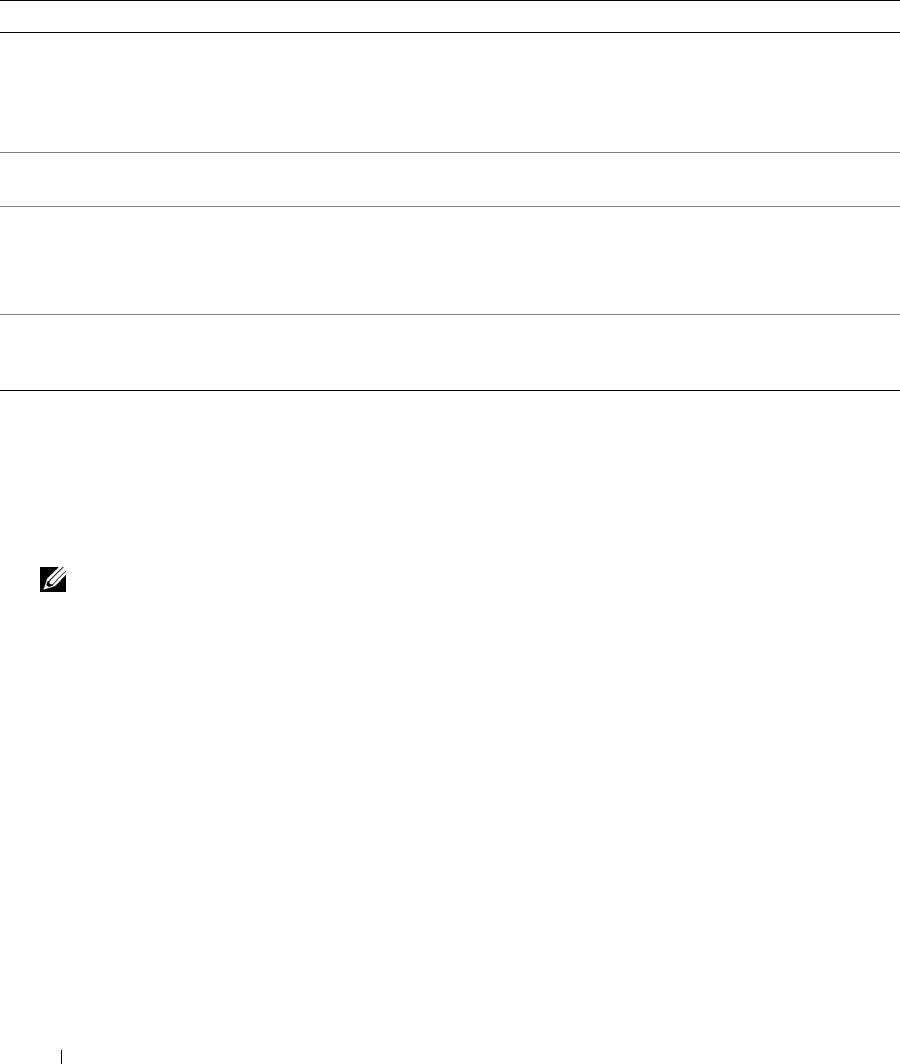
Table 1-8. System Messages (continued)
Message Causes Corrective Actions
Time-of-day not set -
Incorrect Time or Date settings; faulty
Check the Time and Date settings. See
please run SETUP program
system battery.
"Using the System Setup Program" on
page 31. If the problem persists, replace
the system battery. See "System Battery"
on page 86.
Timer chip counter 2
Faulty system board. See "Getting Help" on page 125.
failed
Unsupported CPU
Microprocessor(s) is not supported by
Install a supported microprocessor or
combination
the system.
microprocessor combination. See
"Processors" on page 67.
Unsupported CPU stepping
detected
Utility partition not
The <F10> key was pressed during
Create a utility partition on the boot hard
available
POST, but no utility partition exists on
drive. See the CDs that came with your
the boot hard drive.
system.
Warning Messages
A warning message alerts you to a possible problem and prompts you to respond before the system
continues a task. For example, before you format a diskette, a message will warn you that you may lose all
data on the diskette. Warning messages usually interrupt the task and require you to respond by typing
y
(yes) or
n (no).
NOTE: Warning messages are generated by either the application or the operating system. For more information,
see the documentation that accompanied the operating system or application.
Diagnostics Messages
When you run system diagnostics, an error message may result. Diagnostic error messages are not covered
in this section. Record the message on a copy of the Diagnostics Checklist in "Getting Help" on page 125,
and then follow the instructions in that section for obtaining technical assistance.
Alert Messages
Systems management software generates alert messages for your system. Alert messages include
information, status, warning, and failure messages for drive, temperature, fan, and power conditions. For
more information, see the systems management software documentation.
30 About Your System
