Dell Latitude D610: System Board
System Board : Dell Latitude D610
Back to Contents Page
System Board
Dell™Latitude™D610ServiceManual
Removing the System Board
Installing the System Board
Removing the System Board
The system board's BIOS chip contains the Service Tag, which is also visible on a barcode label on the bottom of the computer. The replacement kit for the
system board includes a CD that provides a utility for transferring the Service Tag to the replacement system board.
1. Follow the instructions in "Preparing to Work Inside the Computer."
2. Remove the center control cover (see "Removing the Center Control Cover").
3. Remove the keyboard (see "Removing the Keyboard").
4. Remove the display assembly (see "Removing the Display Assembly").
5. Remove the palm rest (see "Removing the Palm Rest").
6. Remove the fan (see "Removing the Fan").
7. Remove the microprocessor thermal-cooling assembly (see "Removing the Microprocessor Thermal-Cooling Assembly").
8. Remove the microprocessor (see "Removing the Microprocessor Module").
9. Remove the speaker assembly (see "Removing the Speaker Assembly").
10. Remove the internal card with Bluetooth® wireless technology (see step #4).
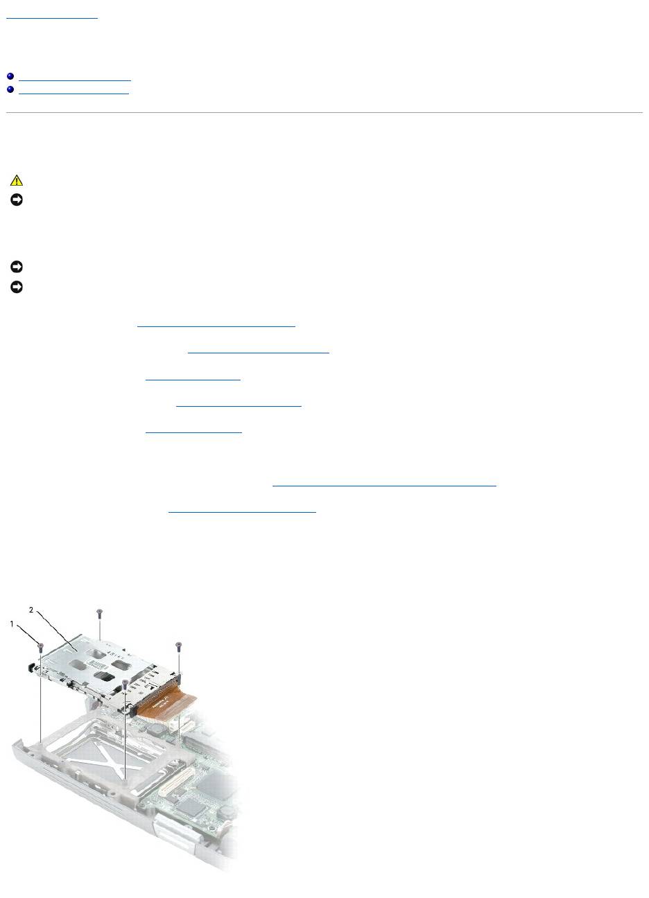
11. Remove the four M2x3 screws that secure the PCMCIA card cage to the system board.
CAUTION: Before you begin any of the procedures in this section, follow the safety instructions in the Product Information Guide.
NOTICE: To avoid electrostatic discharge, ground yourself by using a wrist grounding strap or by periodically touching an unpainted metal surface (such
as the back panel) on the computer.
NOTICE: Disconnect the computer and any attached devices from electrical outlets, and remove any installed batteries.
NOTICE: To avoid electrostatic discharge, ground yourself by using a wrist grounding strap or by touching an unpainted metal surface on the computer.
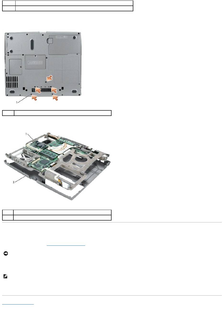
12. Turn the computer over and remove the five M2 x 3-mm screws labeled "B" that secure the system board assembly to the computer base.
13. Pull out the system board assembly starting from the front of the palm rest.
Installing the System Board
1. Follow all of the steps in "Removing the System Board" in reverse order.
2. Turn on the computer.
3. Insert the CD that accompanied the replacement system board into the appropriate drive. Follow the instructions that appear on the screen.
Back to Contents Page
1
M2.5 x 4-mm screws (4)
2
PCMCIA card cage
1
M2 x 3-mm screws (5)
1
system board assembly
2
computer base
NOTICE: Before turning on the computer, replace all screws and ensure that no stray screws remain inside the computer. Failure to do so may result in
damage to the computer.
NOTE: After replacing the system board, enter the computer Service Tag into the BIOS of the replacement system board.

Оглавление
- Dell™Latitude™D610ServiceManual
- Before You Begin
- Flashing the BIOS
- Internal Card With Bluetooth® Wireless Technology
- Coin-Cell Battery
- Microprocessor Module
- Display Assembly and Display Latch
- Fan
- Hard Drive
- Center Control Cover
- Keyboard
- Base Latch
- Mini PCI Card
- Palm Rest
- Pin Assignments for I/O Connectors
- Speaker Assembly
- System Board
- System Components
- Microprocessor Thermal-Cooling Assembly
- Memory Module, Modem, and Devices
