Dell Latitude D610: Display Assembly and Display Latch
Display Assembly and Display Latch : Dell Latitude D610
Back to Contents Page
Display Assembly and Display Latch
Dell™Latitude™D610ServiceManual
Display Assembly
Display Bezel
Display Panel
Display Latch
Display Assembly
Removing the Display Assembly
1. Follow the instructions in "Preparing to Work Inside the Computer."
2. Remove the center control cover (see "Removing the Center Control Cover").
3. Remove the keyboard (see "Removing the Keyboard").
4. Open the display approximately 180 degrees so that it lies flat against your work surface.
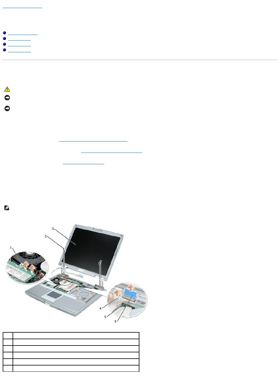
5. Loosen the captive screw that secures the display cable to the heat sink on the system board.
6. Use the pull-tab to remove the display cable from the display connector on the system board.
7. Remove the four M2.5 x 5-mm screws.
CAUTION: Before you begin any of the procedures in this section, follow the safety instructions in the Product Information Guide.
NOTICE: To avoid electrostatic discharge, ground yourself by using a wrist grounding strap or by periodically touching an unpainted metal surface (such
as the back panel) on the computer.
NOTICE: You must remove the display assembly before you remove the palm rest.
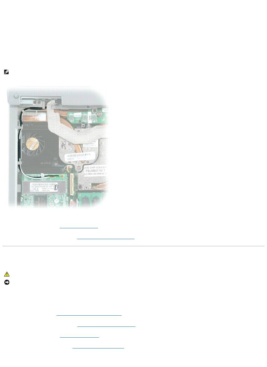
NOTE: If a Mini PCI card is installed, remove the two antenna cables from the card and from the routing clips.
1
antenna cables (2)
2
M2.5 x 5-mm screws (4)
3
display
4
captive screw on heat sink
5
display connector on system board
6
pull-tab on display-cable connector
8. Lift the display assembly up and out of the computer base.
Installing the Display Assembly
1. Align the display assembly over the screw holes in the base of the computer.
2. Tighten the four M2.5 x 5-mm screws.
3. Route the two antenna cables under the routing clips.
4. Replace the keyboard (see "Installing the Keyboard").
5. Replace the center control cover (see "Installing the Center Control Cover").
Display Bezel
Removing the Display Bezel
1. Follow the instructions in "Preparing to Work Inside the Computer."
2. Remove the center control cover (see "Removing the Center Control Cover").
3. Remove the keyboard (see "Removing the Keyboard").
4. Remove the display assembly (see "Removing the Display Assembly").
5. Use a plastic scribe tool to pry the six display bumpers out of the screw holes located on the front of the bezel.
NOTE: Ensure that you route the antenna cables under the routing clips. Failure to do so could result in your keyboard not seating properly.
CAUTION: Before you begin any of the procedures in this section, follow the safety instructions in the Product Information Guide.
NOTICE: To avoid electrostatic discharge, ground yourself by using a wrist grounding strap or by periodically touching an unpainted metal surface (such
as the back panel) on the computer.
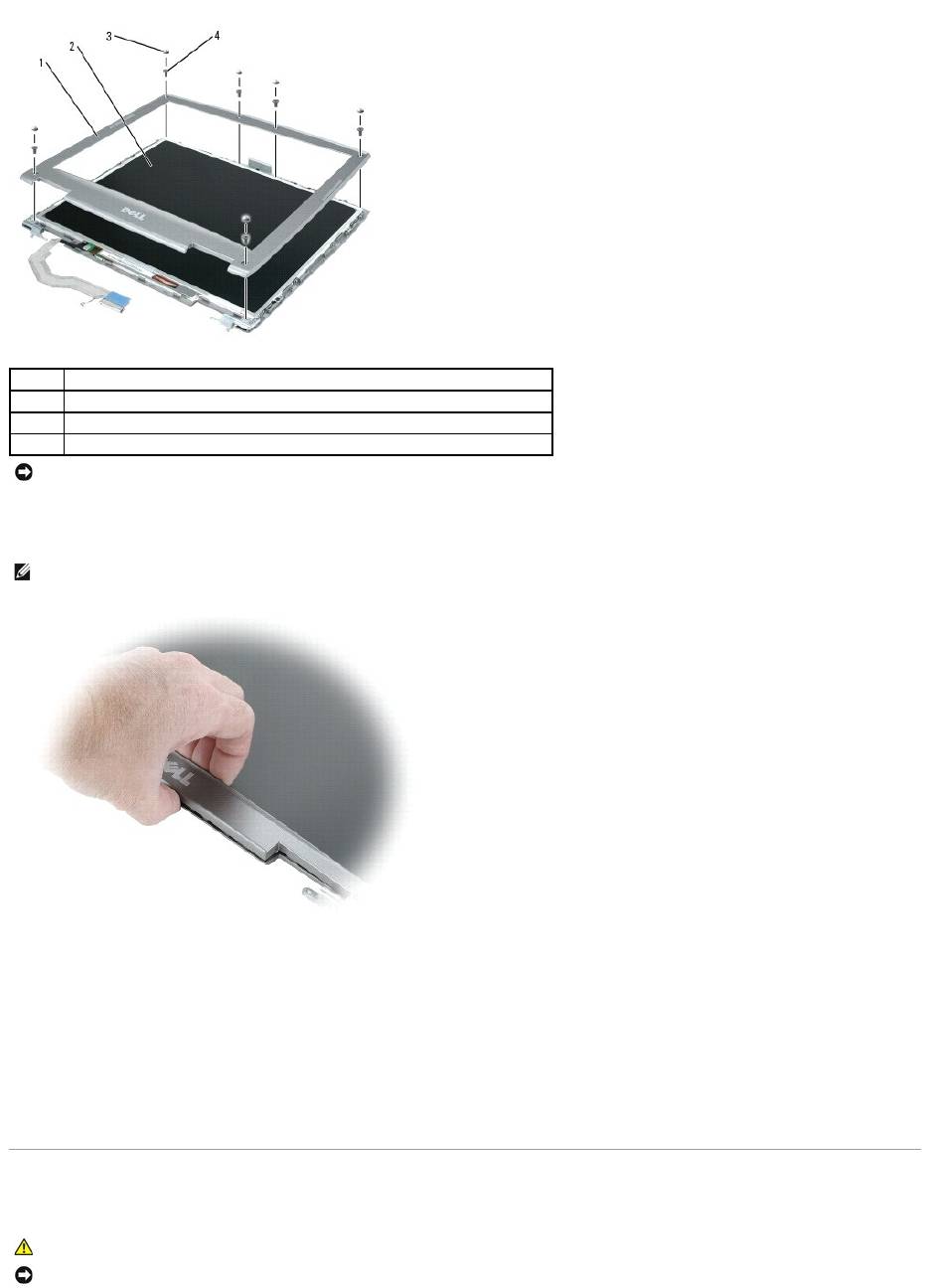
6. Remove the six M2.5 x 5-mm screws located on the front of the bezel.
7. Startingatthebottomofthedisplaypanel(bytheDell™logo),useyourfingerstoseparatethebezelfromthetopcoverbyliftingtheinsideedgeofthe
bezel and rotating away from the top cover.
Installing the Display Bezel
1. Starting at any corner, use your fingers to gently snap the bezel in place securing the display panel.
2. Tighten the six M2.5 x 5-mm screws on the front of the bezel.
3. Replace the six display bumpers around the display assembly.
Display Panel
1
display bezel
2
display panel
3
display bumpers (6)
4
M2.5 x 5-mm screws (6)
NOTICE: Carefully separate the bezel from the top cover to avoid damage to the bezel.
NOTE: Follow the same procedure on all four sides of the display bezel until it snaps completely off.
CAUTION: Before you begin any of the procedures in this section, follow the safety instructions in the Product Information Guide.
NOTICE: To avoid electrostatic discharge, ground yourself by using a wrist grounding strap or by touching an unpainted metal surface on the computer.
Removing the Display Panel
1. Follow the instructions in "Preparing to Work Inside the Computer."
2. Remove the center control cover (see "Removing the Center Control Cover").
3. Remove the keyboard (see "Removing the Keyboard").
4. Remove the display assembly (see "Removing the Display Assembly").
5. Remove the display bezel (see "Removing the Display Bezel").
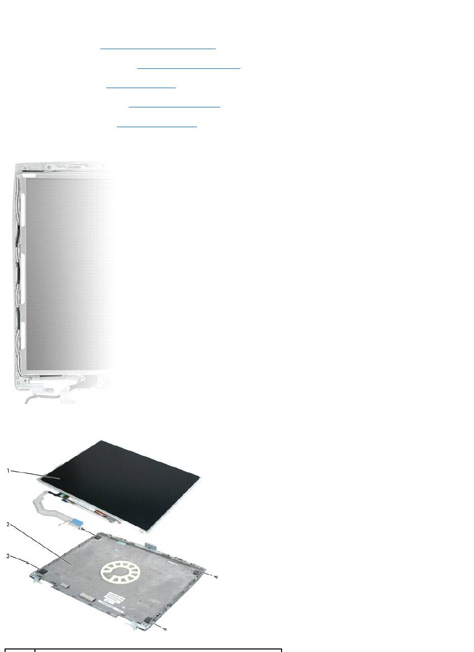
6. Remove the antenna cables from the routing clips on the side of the display panel.
7. Remove the four M2 x 3-mm screws (two on each side) from the display panel.
8. Remove the display panel from the top cover.
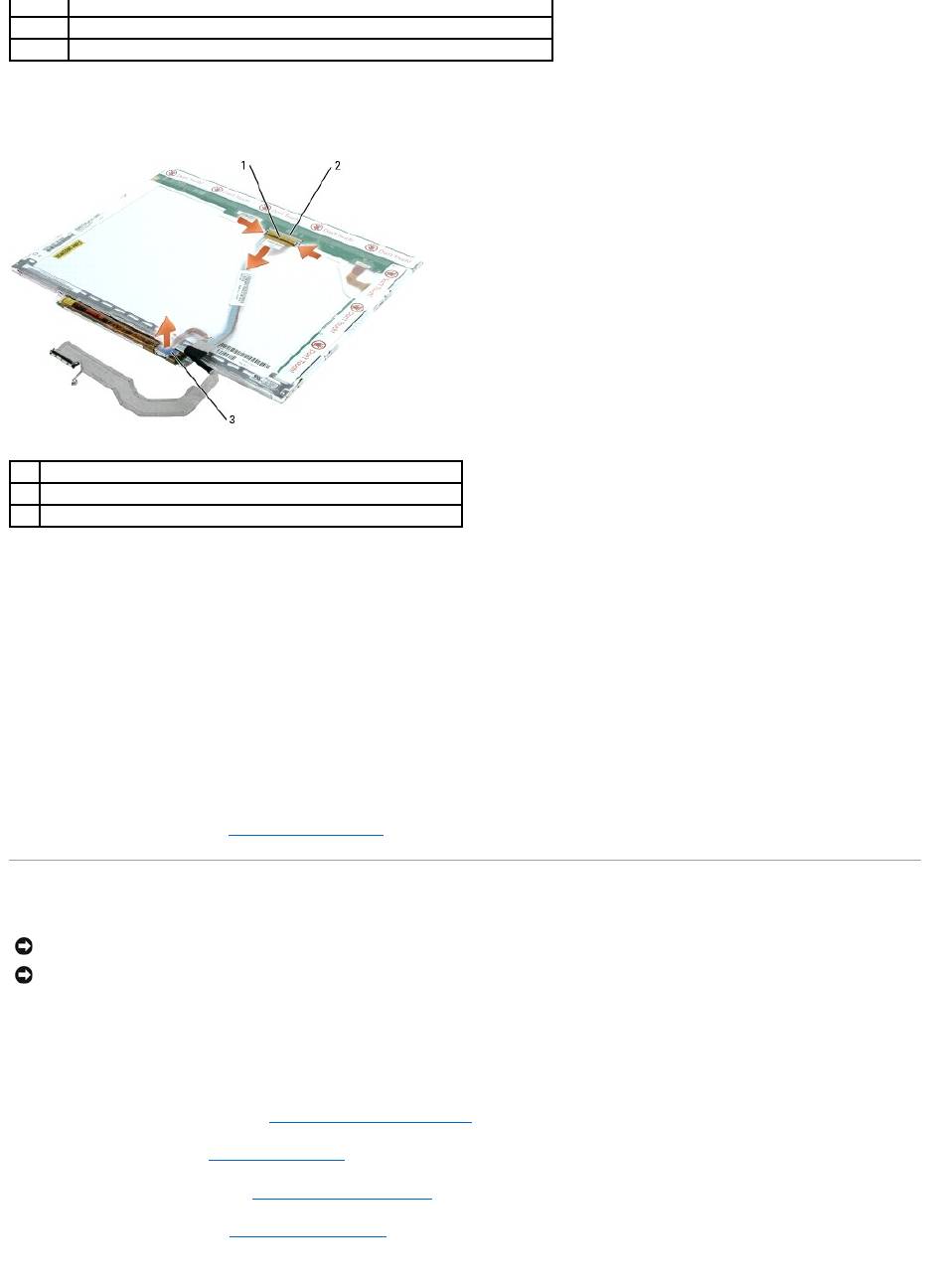
9. Use the pull-tab to disconnect the bottom flex-cable connector from the inverter connector.
10. Press in both sides of the top display cable connector, and pull the display cable connector away from the top flex-cable connector.
Installing the Display Panel
1. Connect the top display cable connector to the top flex-cable connector.
2. Connect the bottom flex-cable connector to the inverter connector.
3. Replace the display panel inside the top cover.
4. Tighten the four M2 x 3-mm screws (two on each side) around the display panel.
5. Replace the display bezel (see "Installing the Display Bezel").
Display Latch
Removing the Display Latch
1. Follow the instructions in "Preparing to Work Inside the Computer."
2. Remove the center control cover (see "Removing the Center Control Cover").
3. Remove the keyboard (see "Removing the Keyboard").
4. Remove the display assembly (see "Removing the Display Assembly").
5. Remove the display bezel (see "Removing the Display Bezel").
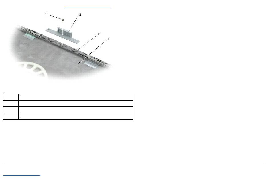
6. Remove the M2.5 x 5-mm screw that secures the display latch to the top cover.
1
display panel
2
top cover
3
M2 x 3-mm screws (4)
1
top flex-cable connector
2
top display-cable connector
3
pull-tab on bottom flex-cable connector
NOTICE: Disconnect the computer and any attached devices from electrical outlets, and remove any installed batteries.
NOTICE: To avoid electrostatic discharge, ground yourself by using a wrist grounding strap or by touching an unpainted metal surface on the computer.
7. Remove the display latch (see "Removing the Display Latch").
Installing the Display Latch
1. Align the latch on the guide pins located on the top cover.
2. Insert and tighten the M2.5 x 5-mm screw that secures the display latch to the top cover.
Back to Contents Page
1
M2.5 x 5-mm screw
2
display latch
3
guide pins (2)
4
top cover
Оглавление
- Dell™Latitude™D610ServiceManual
- Before You Begin
- Flashing the BIOS
- Internal Card With Bluetooth® Wireless Technology
- Coin-Cell Battery
- Microprocessor Module
- Display Assembly and Display Latch
- Fan
- Hard Drive
- Center Control Cover
- Keyboard
- Base Latch
- Mini PCI Card
- Palm Rest
- Pin Assignments for I/O Connectors
- Speaker Assembly
- System Board
- System Components
- Microprocessor Thermal-Cooling Assembly
- Memory Module, Modem, and Devices
