Dell Latitude D610: Memory Module, Modem, and Devices
Memory Module, Modem, and Devices : Dell Latitude D610
Back to Contents Page
Memory Module, Modem, and Devices
Dell™Latitude™D610ServiceManual
Memory Module
Modem
Devices
Memory Module
Your computer has two user-accessible SODIMM sockets, one accessed from beneath the keyboard (DIMM A), and the other accessed from the bottom of the
computer (DIMM B).
Removing the Memory Module From DIMM A
1. Follow the instructions in "Preparing to Work Inside the Computer."
2. Remove the center control cover (see "Removing the Center Control Cover").
3. Remove the keyboard (see "Removing the Keyboard").
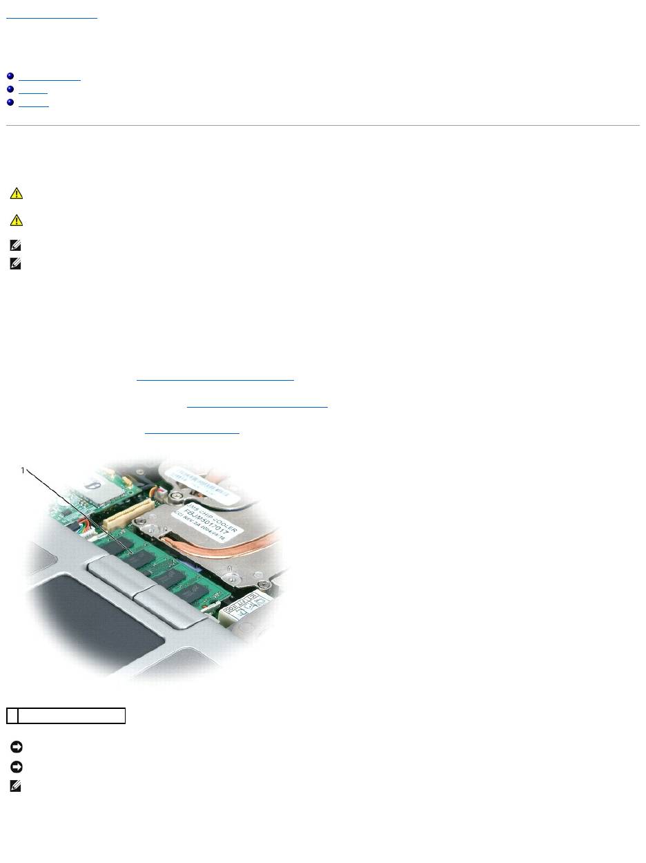
4. Use your fingertips to carefully spread apart the securing clips on each end of the memory module connector until the module pops up.
5. Remove the module from the connector.
CAUTION: Before you begin any of the procedures in this section, follow the safety instructions in the Product Information Guide.
CAUTION: To prevent static damage to components inside your computer, discharge static electricity from your body before you touch any of
your computer's electronic components. You can do so by touching an unpainted metal surface.
NOTE: You can only use DDR2 memory modules in your computer.
NOTE: Memory modules purchased from Dell are covered under your computer warranty.
1
memory module (DIMM A)
NOTICE: To prevent damage to the memory module connector, do not use tools to spread the inner metal tabs that secure the memory module.
NOTICE: Handle memory modules by their edges, and do not touch the components on a module.
NOTE: If you are replacing a memory module, remove the existing module.
Removing the Memory Module From DIMM B
1. Follow the instructions in "Preparing to Work Inside the Computer."
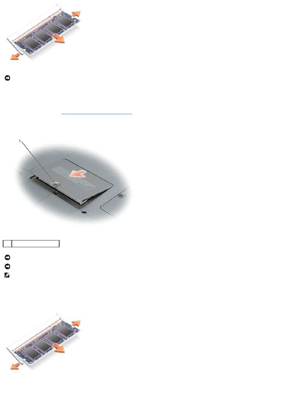
2. Turn the computer over, loosen the captive screw in the memory module cover, and then remove the cover.
3. Use your fingertips to carefully spread apart the securing clips on each end of the memory module connector until the module pops up.
4. Remove the module from the connector.
Installing the Memory Module
NOTICE: If you need to install memory modules in two connectors, install a memory module in the connector labeled "DIMM B" before you install a
module in the connector labeled "DIMM A."
1
captive screw
NOTICE: To prevent damage to the memory module connector, do not use tools to spread the inner metal tabs that secure the memory module.
NOTICE: Handle memory modules by their edges, and do not touch the components on a module.
NOTE: If you are replacing a memory module, remove the existing module.
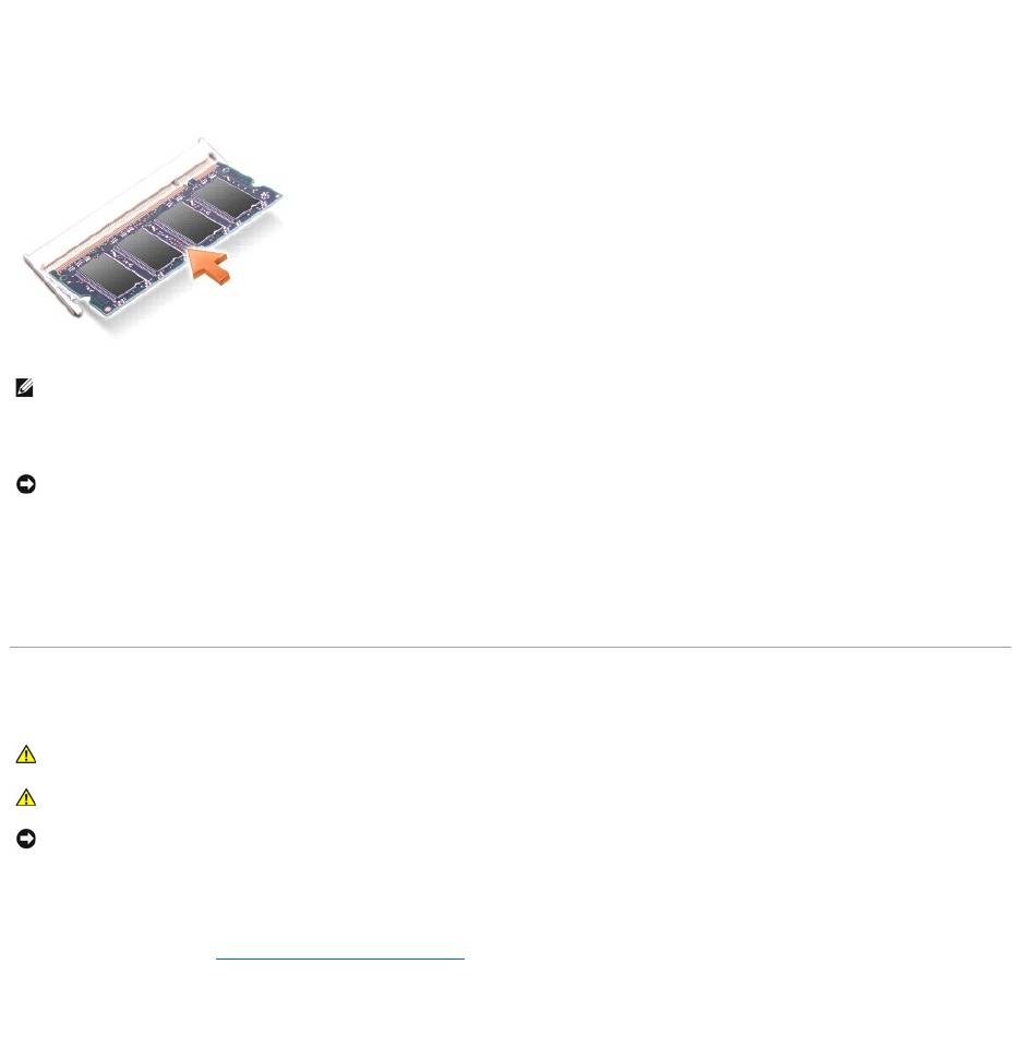
1. Ground yourself and install the new memory module:
a. Align the notch in the module with the slot in the center of the connector.
b. Slide the edge of the module firmly into the connector, and rotate the module down until you feel a click. If you do not feel the click, remove the
module and reinstall it.
2. Replace the cover and tighten the captive screw.
3. Insert the battery into the battery bay, or connect the AC adapter to your computer and an electrical outlet.
4. Turn on the computer.
As the computer boots, it detects the additional memory and automatically updates the system configuration information.
Modem
Removing the Modem
1. Follow the instructions in "Preparing to Work Inside the Computer."
2. Turn the computer over, and loosen the captive screw on the modem cover.
3. Place your finger under the indentation and lift the cover open.
NOTE: If the memory module is not installed properly, the computer does not boot. No error message indicates this failure.
NOTICE: If the memory module cover is difficult to close, remove the module and reinstall it. Forcing the cover to close may damage your computer.
CAUTION: Before you begin any of the procedures in this section, follow the safety instructions in the Product Information Guide.
CAUTION: To prevent static damage to components inside your computer, discharge static electricity from your body before you touch any of
your computer's electronic components. You can do so by touching an unpainted metal surface.
NOTICE: Handle components and cards by their edges, and avoid touching pins and contacts.
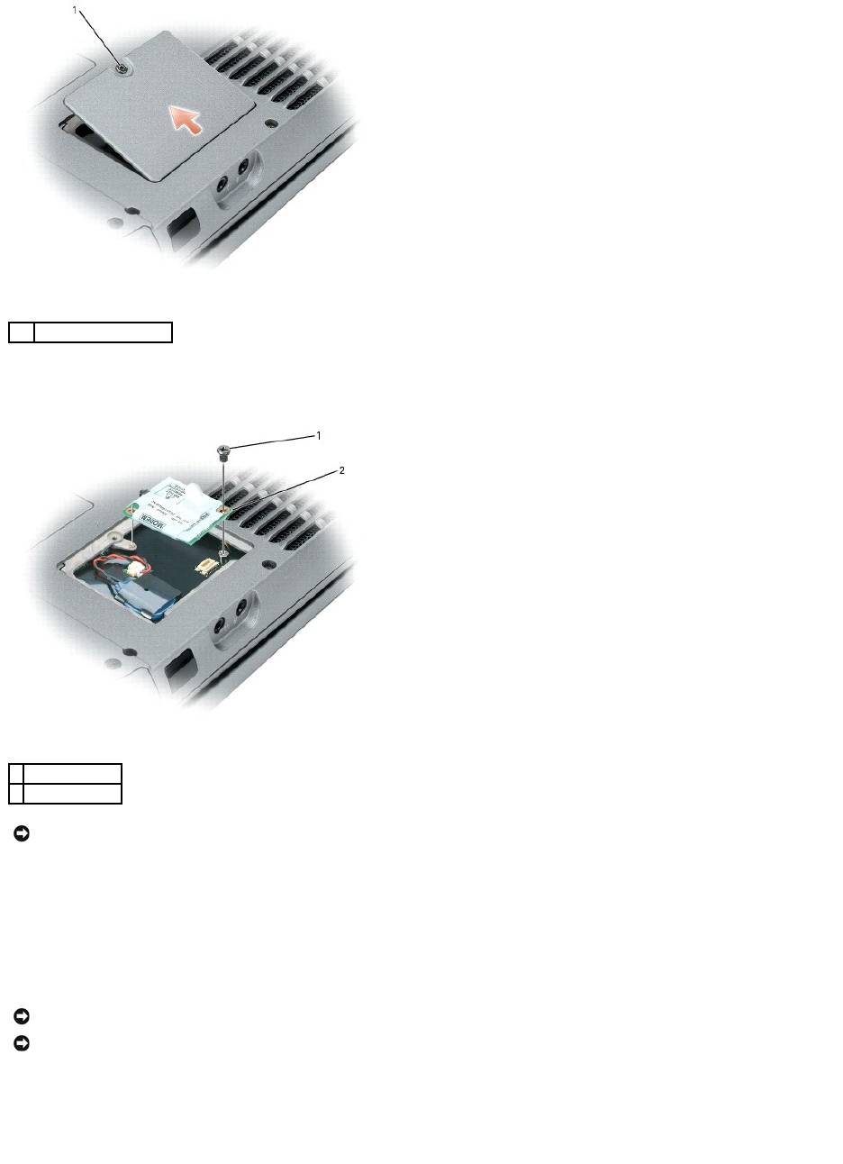
4. Remove the M2 x 3-mm screw that attaches the modem.
5. Pull up on the pull-tab to disconnect the modem from the connector on the system board.
6. Disconnect the modem cable from the modem.
Installing the Modem
1. Connect the modem cable to the modem.
2. Align the connector on the bottom of the modem with the modem connector on the system board and then press down on the right side of the modem
to seat both connectors.
3. Replace the M2 x 3-mm screw.
1
captive screw
1
M2 x 3-mm screw
2
modem
NOTICE: Do not disconnect the modem cable from the system board.
NOTICE: Ensure that the modem cable is routed correctly when you replace the modem.
NOTICE: Do not press down on the left side of the modem while installing it.
4. Replace the modem cover.
Devices
Your computer ships with an optical drive installed in the module bay. However, the device security screw is not installed in the optical drive but packaged
separately. When you install your device in the module bay, you can install the device security screw.
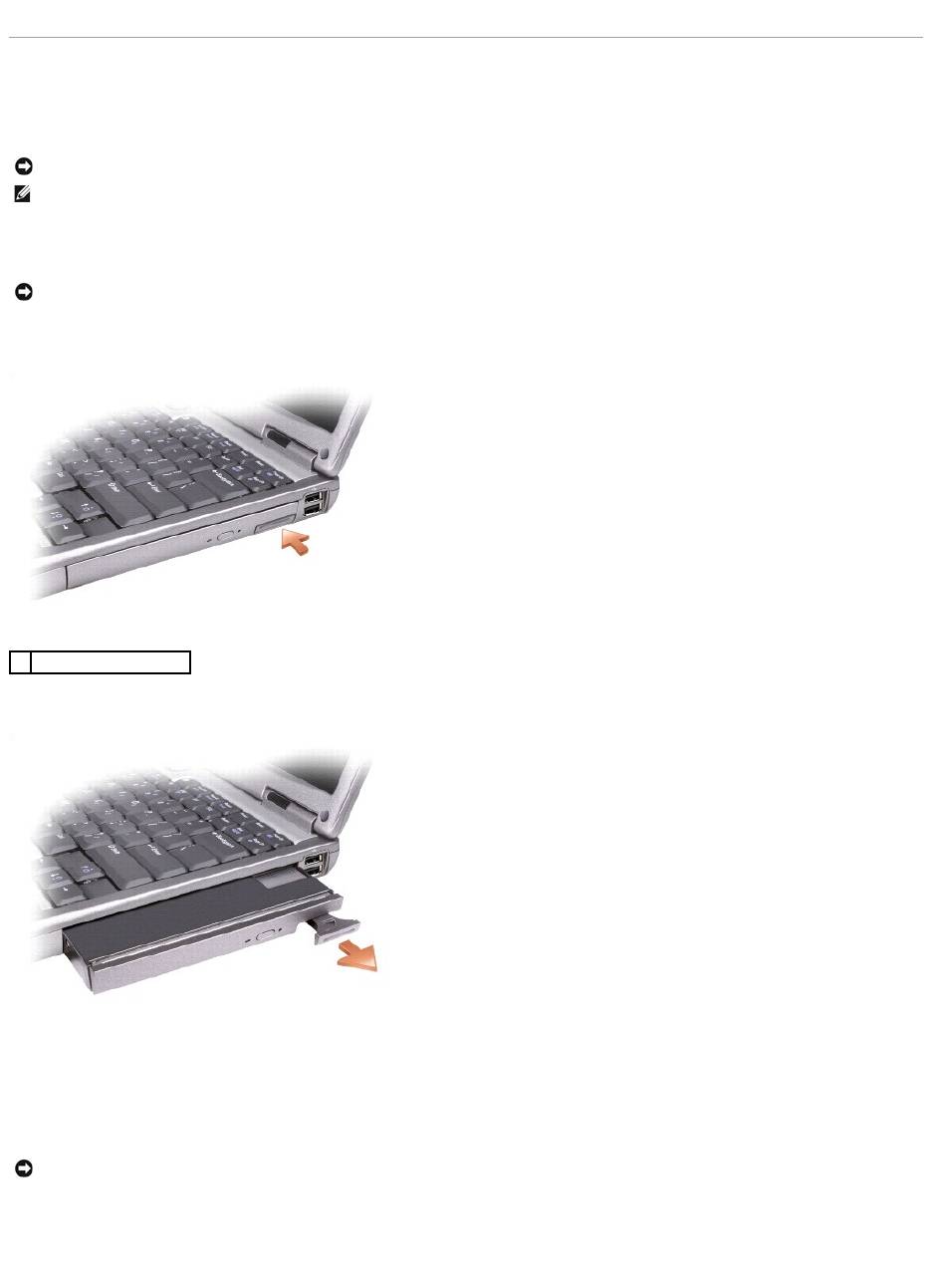
Removing the Device if the Security Screw Is Not Installed
1. Press the device latch release so that the latch release pops out.
2. Pull the device by the latch release to remove the device from the module bay.
Removing the Device if the Security Screw Is Installed
1. If the computer is connected to a docking device (docked), undock it. See the documentation that came with your docking device for instructions.
2. Close the display and turn the computer over.
3. Use a #1 Phillips screwdriver to remove the M2 x 3-mm screw from the bottom of the computer.
NOTICE: Insert devices into the module bay before you dock and turn on the computer.
NOTE: You do not need to install the device security screw unless you want to secure the module inside the computer for security purposes.
NOTICE: To prevent damage to devices, place them in a safe, dry place when they are not installed in the computer. Avoid pressing down on them or
placing heavy objects on top of them.
1
device latch release
NOTICE: To prevent damage to devices, place them in a safe, dry place when they are not installed in the computer. Avoid pressing down on them or
placing heavy objects on top of them.
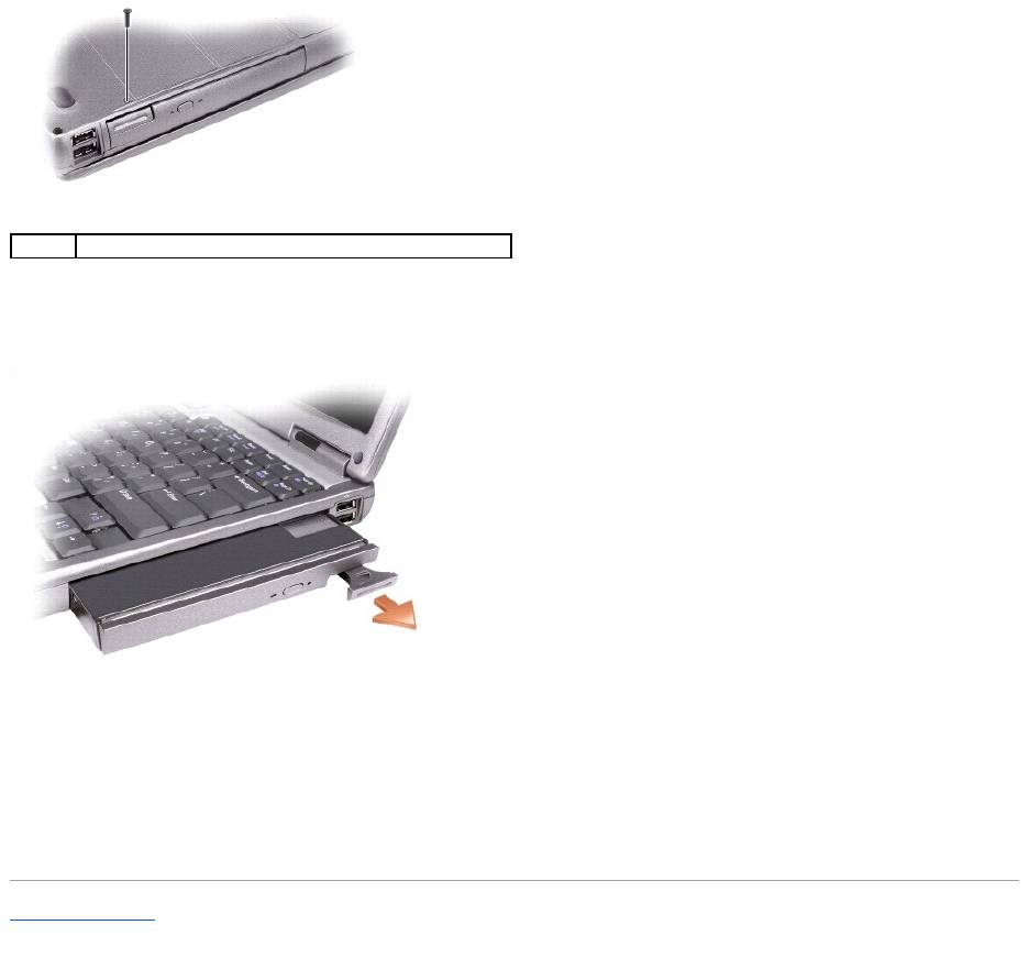
4. Press the device latch release so that the latch release pops out.
5. Pull the device by the latch release to remove the device from the module bay.
Installing the Device
1. Slide the device into the bay until it clicks in place.
2. Press the latch release back into position and replace the security screw if needed.
Back to Contents Page
1
M2 x 3-mm screw
Оглавление
- Dell™Latitude™D610ServiceManual
- Before You Begin
- Flashing the BIOS
- Internal Card With Bluetooth® Wireless Technology
- Coin-Cell Battery
- Microprocessor Module
- Display Assembly and Display Latch
- Fan
- Hard Drive
- Center Control Cover
- Keyboard
- Base Latch
- Mini PCI Card
- Palm Rest
- Pin Assignments for I/O Connectors
- Speaker Assembly
- System Board
- System Components
- Microprocessor Thermal-Cooling Assembly
- Memory Module, Modem, and Devices
