Asus M4A785TD-V EVO U3S6: 1.10 Connectors
1.10 Connectors: Asus M4A785TD-V EVO U3S6
1.10 Connectors
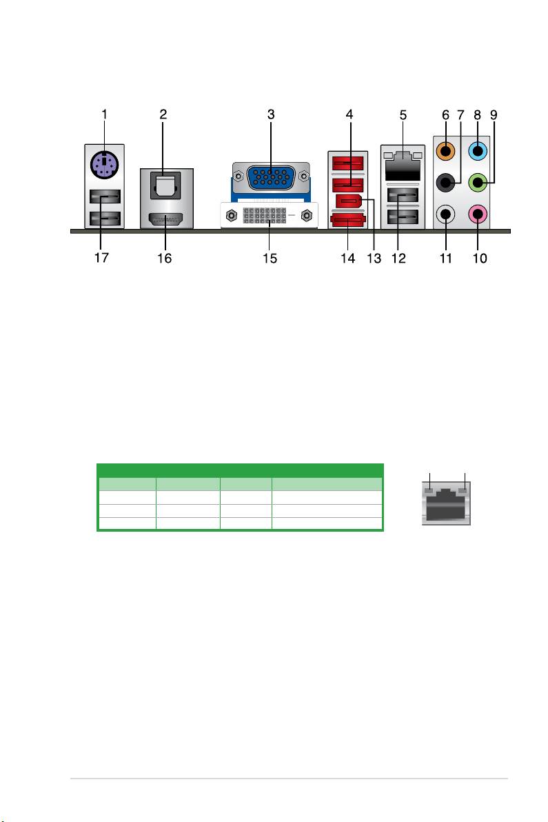
1.10.1 Rear panel ports
1. PS/2 Keyboard/Mouse Combo port (purple). This port is for a PS/2 keyboard or
mouse.
2. Optical S/PDIF_OUT port.
This port connects to an external audio output device via
an optical S/PDIF cable.
3. Video Graphics Adapter (VGA) port.
This 15-pin port is for a VGA monitor or other
VGA-compatible devices.
4. USB 2.0 ports 3 and 4.
These two 4-pin Universal Serial Bus (USB) ports are for USB
2.0 devices.
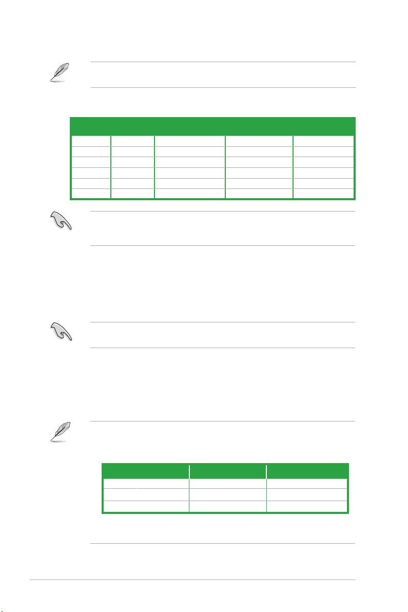
5. LAN (RJ-45) port.
This port allows Gigabit connection to a Local Area Network (LAN)
through a network hub.
LAN port LED indications
ACT/LINK
SPEED
LED
LED
Activity/Link LED Speed LED
Status Description Status Description
OFF No link OFF 10Mbps connection
ORANGE Linked ORANGE 100Mbps connection
BLINKING Data activity GREEN 1Gbps connection
LAN port
6. Center/Subwoofer port (orange). This port connects to the center/subwoofer
speakers.
7. Rear Speaker Out port (black).
This port connects to the rear speakers in the
4, 6, and 8-channel audio congurations.
8. Line In port (light blue).
This port connects to the tape, CD, DVD player, or other
audio sources.
9. Line Out port (lime).
This port connects to a headphone or a speaker. In the 4, 6 and
8-channel congurations, the function of this port becomes Front Speaker Out.
10. Microphone port (pink).
This port connects to a microphone.
11. Side Speaker Out port (gray).
This port connects to the side speakers in the
8-channel audio conguration.
ASUS M4A785TD-V EVO 1-19
Refer to the audio conguration table below for the function of the audio ports in the 2, 4, 6,
or 8-channel conguration.
Audio 2, 4, 6, or 8-channel conguration
Headset
Port
4-channel 6-channel 8-channel
2-channel
Light Blue Line In Line In Line In Line In
Lime Line Out Front Speaker Out Front Speaker Out Front Speaker Out
Pink Mic In Mic In Mic In Mic In
Orange – – Center/Subwoofer Center/Subwoofer
Black – Rear Speaker Out Rear Speaker Out Rear Speaker Out
Gray – – – Side Speaker Out
Ensure the audio device of sound playback is VIA High Denition Audio (the name may
be different based on the OS). Go to Start > Control Panel > Sounds and Audio Devices
> Sound Playback to congure the settings.
12. USB 2.0 ports 1 and 2. These two 4-pin Universal Serial Bus (USB) ports are for
USB 2.0 devices.
13. IEEE 1394a port.
This 6-pin IEEE 1394a port provides high-speed connectivity for
audio/video devices, storage peripherals, PCs, or portable devices.
14. eSATA port.
This port connects to an external Serial ATA hard disk drive.
To use hot-plug, set the OnChip SATA Type item in the BIOS to [AHCI]. See section 2.3.4
SATA Conguration for details.
15. DVI-D Out port. This port is for any DVI-D compatible device and is HDCP compliant
allowing playback of HD DVD, Blu-Ray, and other protected content.
16. HDMI port.
This port is for a High-Denition Multimedia Interface (HDMI) connector,
and is HDCP compliant allowing playback of HD DVD, Blu-Ray, and other protected
content.
Dual display output support
• This table indicates that whether the following dual display outputs are supported on
your motherboard:
Dual display outputs Supported Not supported
DVI + D-Sub •
DVI + HDMI •
HDMI + D-Sub •
• During POST, only the monitor connected to the D-Sub port has display. The dual
display function works only under Windows.
Chapter 1: Product introduction1-20
Playback of HD DVD and Blu-Ray discs
• For better playback quality, we recommend that you follow the system requirements
listed below.
Suggested list
®
CPU AMD
Phenom™ II x3 720
DIMM DDR3 1333 (1GB or higher)
BIOS setup Frame Buffer Size--256MB or higher
Best resolution
File format
®
®
Windows
XP Windows
Vista
Non-protected clips 1920 x 1080p 1920 x 1080p
HD-DVD 1920 x 1080p 1280 x 1080p
Blu-Ray 1280 x 1080p 1280 x 1080p
• To play HD DVD or Blu-Ray disc, ensure to use HDCP compliant devices and software.
17. USB 2.0 ports 5 and 6. These two 4-pin Universal Serial Bus (USB) ports are for
USB 2.0 devices.
1.10.2 Internal connectors
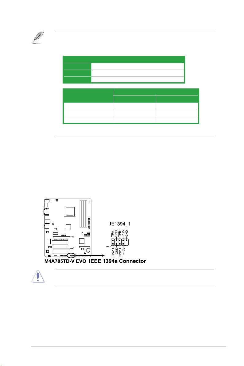
1. IEEE 1394a connector (10-1 pin IE1394_1)
This connector is for an IEEE 1394a port. Connect the IEEE 1394a module cable to this
connector, then install the module to a slot opening at the back of the system chassis.
Never connect a USB cable to the IEEE 1394a connector. Doing so will damage the
motherboard!
ASUS M4A785TD-V EVO 1-21
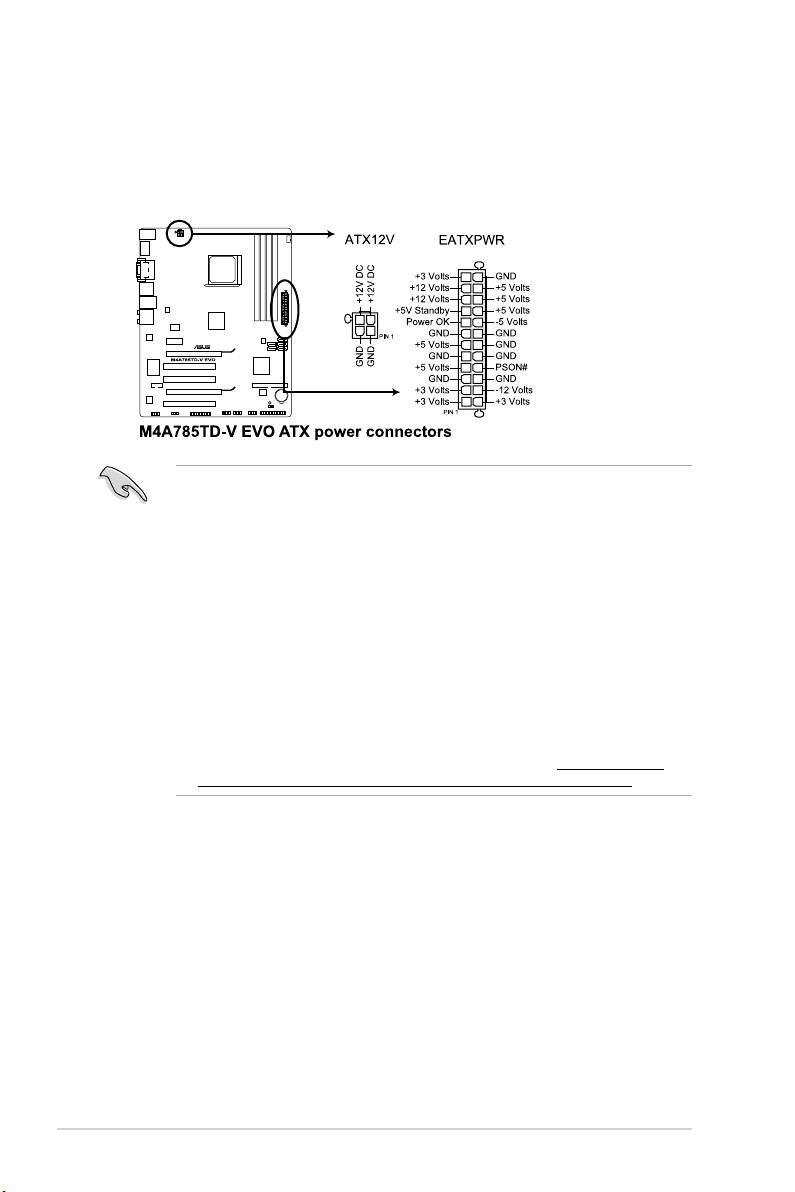
2. ATX power connectors (24-pin EATXPWR, 4-pin ATX12V)
These connectors are for an ATX power supply. The plugs from the power supply are
designed to t these connectors in only one orientation. Find the proper orientation and
push down rmly until the connectors completely t.
•
We recommend that you use an ATX 12V Specication 2.0-compliant power supply unit
(PSU) with a minimum of 300W power rating. This PSU type has 24-pin and 4-pin power
plugs.
•
If you intend to use a PSU with 20-pin and 4-pin power plugs, ensure that the 20-pin
power plug can provide at least 15 A on +12 V and that the PSU has a minimum power
rating of 300W. The system may become unstable or may not boot up if the power is
inadequate.
•
DO NOT forget to connect the 4-pin ATX +12V power plug. Otherwise, the system will
not boot up.
• We recommend that you use a PSU with higher power output when conguring a
system with more power-consuming devices or when you intend to install additional
devices. The system may become unstable or may not boot up if the power is
inadequate.
•
If you are uncertain about the minimum power supply requirement for your system,
refer to the Recommended Power Supply Wattage Calculator at http://support.asus.
com/PowerSupplyCalculator/PSCalculator.aspx?SLanguage=en-us for details.
Chapter 1: Product introduction1-22
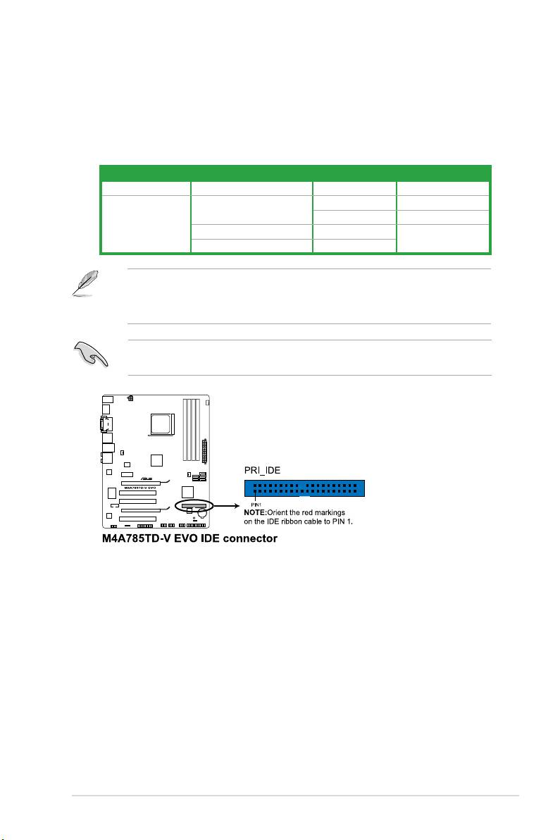
3. IDE connector (40-1 pin PRI_IDE)
The onboard IDE connector is for Ultra DMA 133/100/66 signal cable. There are three
connectors on each Ultra DMA 133/100/66 signal cable: blue, black, and gray. Connect
the blue connector to the motherboard’s IDE connector, then select one of the following
modes to congure your devices:
Drive jumper setting Mode of device(s) Cable connector
Single device Cable-Select or Master - Black
Master Black
Cable-Select
Slave Gray
Two devices
Master Master
Black or gray
Slave Slave
• Pin 20 on the IDE connector is removed to match the covered hole on the Ultra DMA
cable connector. This prevents incorrect insertion when you connect the IDE cable.
• Use the 80-conductor IDE cable for Ultra DMA 133/100/66 IDE devices.
If any device jumper is set as “Cable-Select”, ensure that all other device jumpers have the
same setting.
ASUS M4A785TD-V EVO 1-23
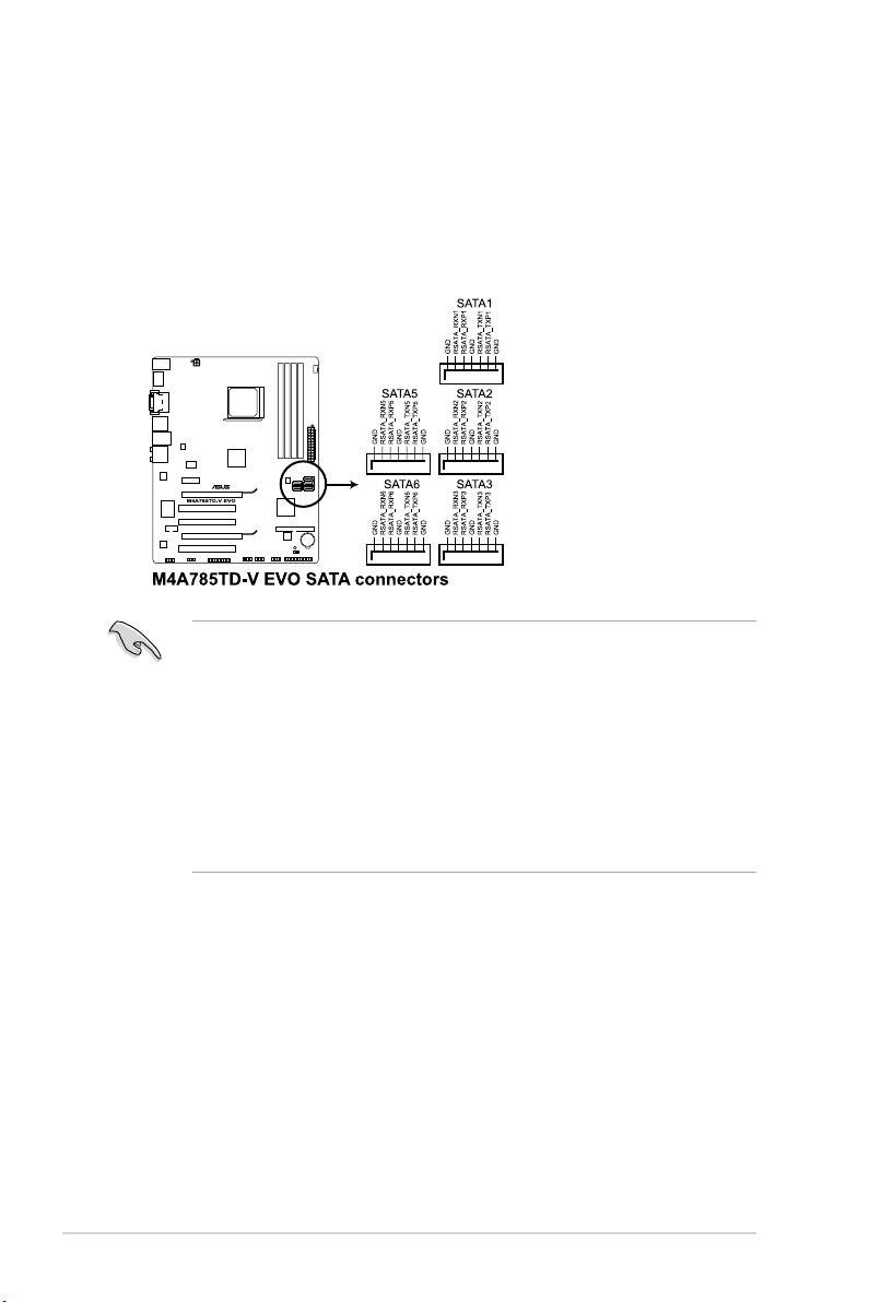
4. Serial ATA connectors (7-pin SATA1, SATA2, SATA3, SATA5, and SATA6)
These connectors are for the Serial ATA signal cables for Serial ATA 3Gb/s hard disk
and optical disk drives. The Serial ATA 3Gb/s is backward compatible with Serial ATA
1.5Gb/s specication. The data transfer rate of the Serial ATA 3Gb/s is faster than the
standard parallel ATA with 133 MB/s (Ultra DMA133). If you install Serial ATA hard disk
drives, you can create a RAID 0, RAID 1, RAID 0+1, or JBOD conguration through the
onboard SB710 chipset.
®
• Install the Windows
XP Service Pack 1 or later versions before using Serial ATA.
• If you intend to create a Serial ATA RAID set using these connectors, set the
OnChip
SATA Type item in the BIOS to [RAID]. See 2.3.4 SATA Conguration for details.
• The motherboard does not provide a oppy disk drive connector. You could use a USB
®
oppy disk drive when installing Windows
XP operating system on a hard disk drive
that includes a RAID/AHCI set.
®
®
• Due to Windows
XP limitation, Windows
XP may not recognize the USB oppy disk
drive.
• For more details on RAID/AHCI, refer to the RAID/AHCI Supplementary Guide included
in the folder named Manual in the support DVD.
Chapter 1: Product introduction1-24
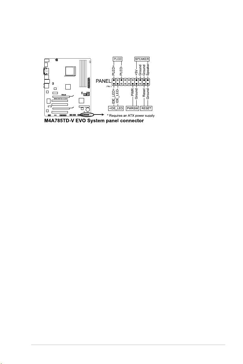
5. System panel connector (20-8 pin PANEL)
This connector supports several chassis-mounted functions.
•
System power LED (2-pin PLED)
This 2-pin connector is for the system power LED. Connect the chassis power LED
cable to this connector. The system power LED lights up when you turn on the system
power, and blinks when the system is in sleep mode.
•
Hard disk drive activity LED (2-pin +IDE_LED)
This 2-pin connector is for the HDD Activity LED. Connect the HDD Activity LED cable
to this connector. The IDE LED lights up or ashes when data is read from or written to
the HDD.
•
System warning speaker (4-pin SPEAKER)
This 4-pin connector is for the chassis-mounted system warning speaker. The speaker
allows you to hear system beeps and warnings.
•
Power/Soft-off button (2-pin PWRSW)
This 2-pin connector is for the system power button. Pressing the power button turns
the system ON or puts the system in SLEEP or SOFT-OFF mode depending on the
BIOS settings. Pressing the power switch for more than four seconds while the system
is ON turns the system OFF.
•
Reset button (2-pin RESET)
This 2-pin connector is for the chassis-mounted reset button for system reboot without
turning off the system power.
ASUS M4A785TD-V EVO 1-25
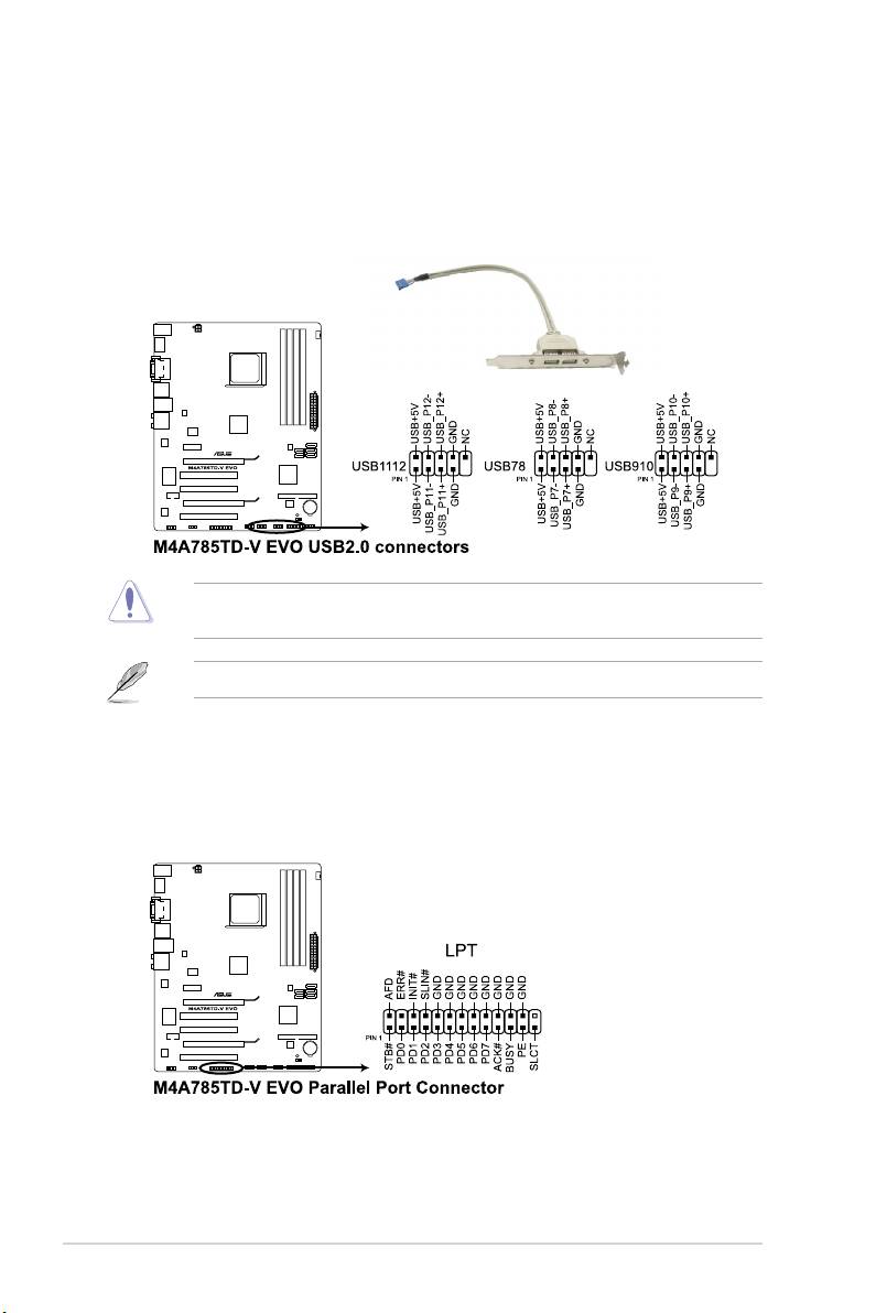
6. USB connectors (10-1 pin USB78, USB910, USB1112)
These connectors are for USB 2.0 ports. Connect the USB module cable to any of
these connectors, then install the module to a slot opening at the back of the system
chassis. These USB connectors comply with USB 2.0 specication that supports up to
480Mbps connection speed.
Never connect a 1394 cable to the USB connectors. Doing so will damage the
motherboard!
The USB 2.0 module is purchased separately.
7. LPT connector (26-1 pin LPT)
The LPT (Line Printing Terminal) connector supports devices such as a printer. LPT is
standardized as IEEE 1284, which is the parallel port interface on IBM PC-compatible
computers.
Chapter 1: Product introduction1-26
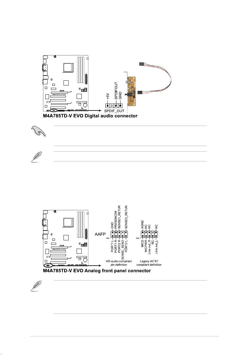
8. Digital audio connector (4-1 pin SPDIF_OUT)
This connector is for an additional Sony/Philips Digital Interface (S/PDIF) port.
Ensure that the audio device of Sound playback is VIA High Denition Audio (the name
may be different based on the OS). Go to Start > Control Panel > Sounds and Audio
Devices > Sound Playback to congure the setting.
The S/PDIF module is purchased separately.
9. Front panel audio connector (10-1 pin AAFP)
This connector is for a chassis-mounted front panel audio I/O module that supports
either High Denition Audio or AC`97 audio standard. Connect one end of the front
panel audio I/O module cable to this connector.
• We recommend that you connect a high-denition front panel audio module to this
connector to avail of the motherboard high-denition audio capability.
• If you want to connect a high denition front panel audio module to this connector, set
the Front Panel Select item in the BIOS to [HD Audio]. See section 2.4.4 Onboard
Device Conguration for details.
ASUS M4A785TD-V EVO 1-27
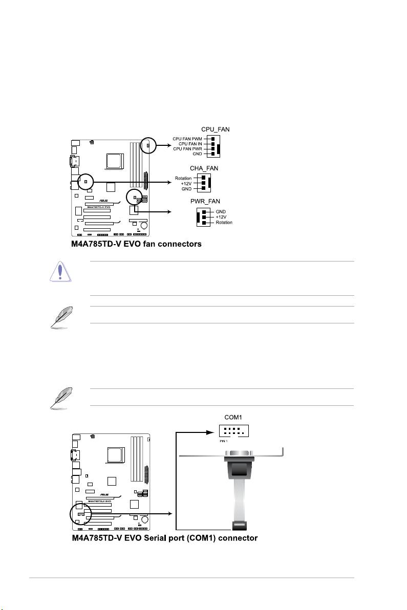
10. Power, CPU, and chassis fan connectors (3-pin PWR_FAN, 4-pin CPU_FAN,
3-pin CHA_FAN)
The fan connectors support cooling fans of 350mA~740mA (8.88W max.) or a total of
1A~2.22A (26.64W max.) at +12V. Connect the fan cables to the fan connectors on the
motherboard, ensuring that the black wire of each cable matches the ground pin of the
connector.
DO NOT forget to connect the fan cables to the fan connectors. Insufcient air ow inside
the system may damage the motherboard components. These are not jumpers! DO NOT
place jumper caps on the fan connectors.
Only the CPU fan supports the ASUS Q-Fan feature.
11. Serial port connector (10-1 pin COM1)
The connector is for a serial (COM) port. Connect the serial port module cable to the
connector, then install the module to a slot opening at the back of the system chassis.
The serial port bracket (COM1) is purchased separately.
Chapter 1: Product introduction1-28
Оглавление
- Contents
- Notices
- Safety information
- About this guide
- M4A785TD-V EVO specications summary
- 1.1 Welcome!
- 1.4 Before you proceed
- 1.5 Motherboard overview
- 1.6 Central Processing Unit (CPU)
- 1.7 System memory
- 1.8 Expansion slots
- 1.9 Jumpers
- 1.10 Connectors
- 1.11 Software support
- 2.1 Managing and updating your BIOS
- 2.2 BIOS setup program
- 2.3 Main menu
- 2.4 Advanced menu
- 2.5 Power menu
- 2.6 Boot menu
- 2.7 Tools menu
- 2.8 Exit menu
