Asus M4A785TD-V EVO U3S6: 1.5 Motherboard overview
1.5 Motherboard overview: Asus M4A785TD-V EVO U3S6
1.5 Motherboard overview
1.5.1 Placement direction
When installing the motherboard, ensure that you place it into the chassis in the correct
orientation. The edge with external ports goes to the rear part of the chassis as indicated in
the image below.
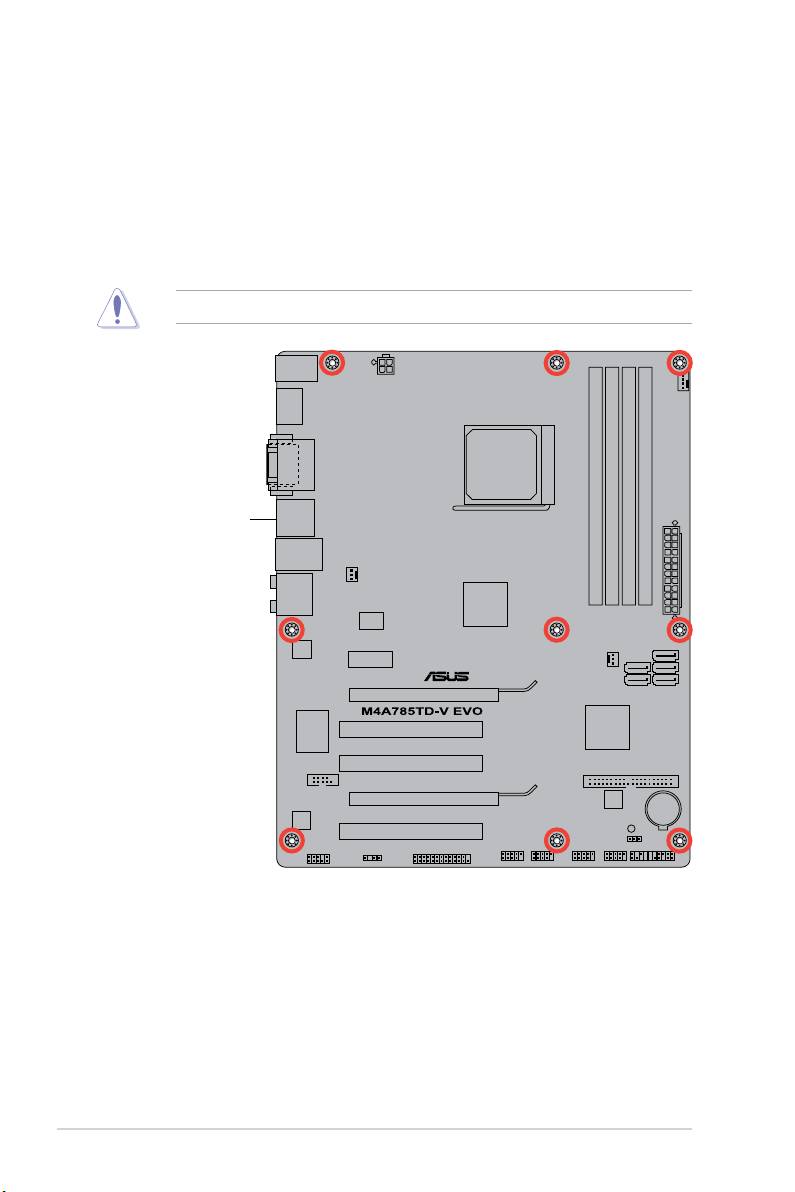
1.5.2 Screw holes
Place nine screws into the holes indicated by circles to secure the motherboard to the
DO NOT overtighten the screws! Doing so can damage the motherboard.
Place this side towards
the rear of the chassis.
Chapter 1: Product introduction1-6
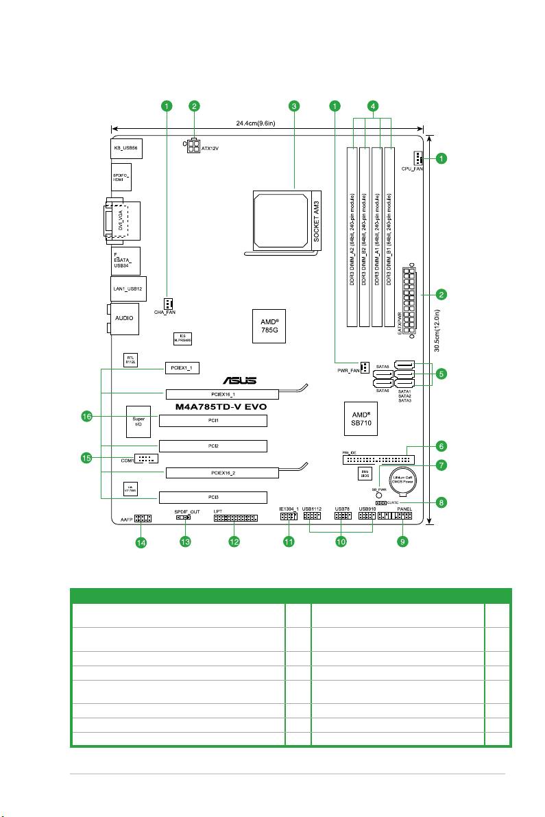
1.5.3 Motherboard layout
1.5.4 Layout contents
Connectors/Jumpers/Slots/LED Page Connectors/Jumpers/Slots/LED Page
1. CPU, power, and chassis fan connectors
1-28 9. System panel connector (20-8 pin PANEL) 1-25
(4-pin CPU_FAN, 3-pin PWR_FAN, and 3-pin CHA_FAN)
2. ATX power connectors (24-pin EATXPWR, 4-pin ATX12V)
1-22 10. USB connectors (10-1 pin USB78, USB910,
1-26
USB1112)
3. CPU Socket AM3
1-8 11. IEEE 1394a connector (10-1 pin IE1394_1) 1-21
4. DDR3 DIMM slots
1-11 12. LPT connector (26-1 pin LPT) 1-26
5. SATA connectors (7-pin SATA1, SATA2, SATA3, SATA5,
1-24 13. Digital audio connector (4-1 pin SPDIF_OUT) 1-27
SATA6)
6. IDE connector (40-1 pin PRI_IDE)
1-23 14. Front panel audio connector (10-1 pin AAFP) 1-27
7. Onboard power LED (SB_PWR)
1-5 15. Serial port connector (10-1 pin COM1) 1-28
8. Clear RTC RAM (3-pin CLRTC)
1-18 16. PCIe x16 / PCIe x1 / PCI slots 1-17
ASUS M4A785TD-V EVO 1-7
Оглавление
- Contents
- Notices
- Safety information
- About this guide
- M4A785TD-V EVO specications summary
- 1.1 Welcome!
- 1.4 Before you proceed
- 1.5 Motherboard overview
- 1.6 Central Processing Unit (CPU)
- 1.7 System memory
- 1.8 Expansion slots
- 1.9 Jumpers
- 1.10 Connectors
- 1.11 Software support
- 2.1 Managing and updating your BIOS
- 2.2 BIOS setup program
- 2.3 Main menu
- 2.4 Advanced menu
- 2.5 Power menu
- 2.6 Boot menu
- 2.7 Tools menu
- 2.8 Exit menu
