Asus Crosshair II Formula: Software
Software: Asus Crosshair II Formula
This chapter describes the contents of
the support DVD that comes with the
motherboard package.
Software
5
support

Chapter summary
5
5.1 Installing an operating system ................................................... 5-1
5.2 Support DVD information ............................................................ 5-1
5.3 Software information ................................................................... 5-9
5.4 RAID congurations .................................................................. 5-24
5.5 Creating a RAID driver disk ....................................................... 5-40
ASUS Crosshair
5.1 Installing an operating system
®
This motherboard supports Windows
2000/2003 Server/XP/64-bit XP operating
systems (OS). Always install the latest OS version and corresponding updates to
maximize the features of your hardware.
• Motherboard settings and hardware options vary. Use the setup
procedures presented in this chapter for reference only. Refer to your OS
documentation for detailed information.
®
®
• Make sure that you install Windows
2000 Service Pack 4 or the Windows
XP Service Pack2 or later versions before installing the drivers for better
compatibility and system stability.
5.2 Support DVD information
The support DVD that came with the motherboard package contains the drivers,
software applications, and utilities that you can install to avail all motherboard
features.
The contents of the support DVD are subject to change at any time without
notice. Visit the ASUS website(www.asus.com) for updates.
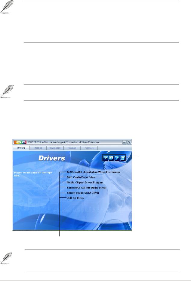
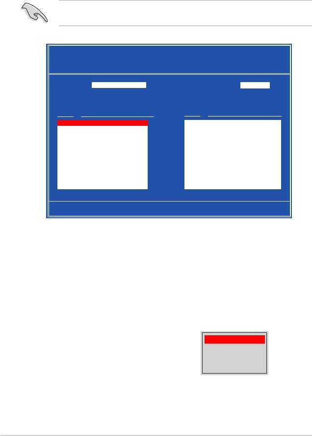
5.2.1 Running the support DVD
Place the support DVD to the optical drive. The DVD automatically displays the
Drivers menu if Autorun is enabled in your computer.
Click an icon to
display support DVD/
motherboard information
Click an item to install
If Autorun is NOT enabled in your computer, browse the contents of the support
DVD to locate the le ASSETUP.EXE from the BIN folder. Double-click the
ASSETUP.EXE to run the DVD.
ASUS Crosshair
5-1

5.2.2 Drivers menu
The drivers menu shows the available device drivers if the system detects installed
devices. Install the necessary drivers to activate the devices.
ASUS InstAll-Drivers Installation Wizard
Installs all of the drivers through the Installation Wizard.
AMD Cool ‘n’ Quiet Driver
Installs the AMD Cool ‘n’ Quiet™ technology driver.
Nvidia Chipset Driver Program
Installs the NVIDIA® Chipset drivers for the NVIDIA® nForce™ 590 SLI chipset.
SoundMAX ADI1988 Audio Driver
Installs the SoundMAX® ADI1988 audio driver and application.
Silicon Image SATA Driver
Installs the Silicon Image® Serial ATA RAID driver.
USB 2.0 Driver
Installs the USB 2.0 driver.
5-2
Chapter 5: Software support

5.2.3 Utilities menu
The Utilities menu shows the applications and other software that the motherboard
supports.
ASUS InstAll-Drivers Installation Wizard
Installs all of the drivers through the Installation Wizard.
3DMark06 Software
Installs the 3DMark06 software.
Adobe Reader V7.0
Installs the Adobe® Acrobat® Reader that allows you to open, view, and print
documents in Portable Document Format (PDF).
ASUS Ai Booster
The ASUS AI Booster application allows you to overclock the CPU speed in
Windows® environment.
ASUS Cool ‘n’ Quiet Utility
Installs the AMD Cool ‘n’ Quiet™ software.
ASUS Update
The ASUS Update utility allows you to update the motherboard BIOS in Windows®
environment. This utility requires an Internet connection either through a network
or an Internet Service Provider (ISP).
ASUS Crosshair
5-3

Microsoft DirectX 9.0c
Installs the Microsoft® DirectX 9.0c driver. The Microsoft DirectX® 9.0c is a
multimedia technology that enhances computer graphics and sound. DirectX®
improves the multimedia features of you computer so you can enjoy watching
TV and movies, capturing videos, or playing games in your computer. Visit the
Microsoft website (www.microsoft.com) for updates.
Anti-Virus Utility
The anti-virus application scans, identies, and removes computer viruses. View
the online help for detailed information.
ASUS PC Probe II
This smart utility monitors the fan speed, CPU temperature, and system voltages,
and alerts you of any detected problems. This utility helps you keep your computer
in healthy operating condition.
ASUS Screen Saver
Bring life to your idle screen by installing the ASUS screen saver.
5-4
Chapter 5: Software support
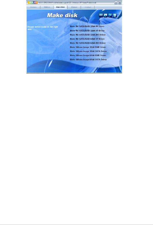
5.2.4 Make Disk menu
The Make Disk menu contains items to create the RAID driver disk.
Make NV SATA/RAID 32bit 2K Driver
Make NV SATA/RAID 32bit XP Driver
Make NV SATA/RAID 32bit 2K3 Driver
Allows you to create an NVIDIA® Serial ATA RAID driver disk for a 32-bit 2K/XP/
2K3 system.
Make NV SATA/RAID 64bit XP Driver
Make NV SATA/RAID 64bit 2K3 Drive
Allows you to create an NVIDIA® Serial ATA RAID driver disk for a 64-bit XP/2K3
system.
Make Silicon Image 32bit RAID Driver
Make Silicon Image 32bit SATA Driver
Allows you to create a Silicon Image® Serial ATA/RAID driver disk for a 32-bit
system.
Make Silicon Image 64bit RAID Driver
Make Silicon Image 64bit SATA Driver
Allows you to create a Silicon Image® Serial ATA/RAID driver disk for a 64-bit
system.
ASUS Crosshair
5-5
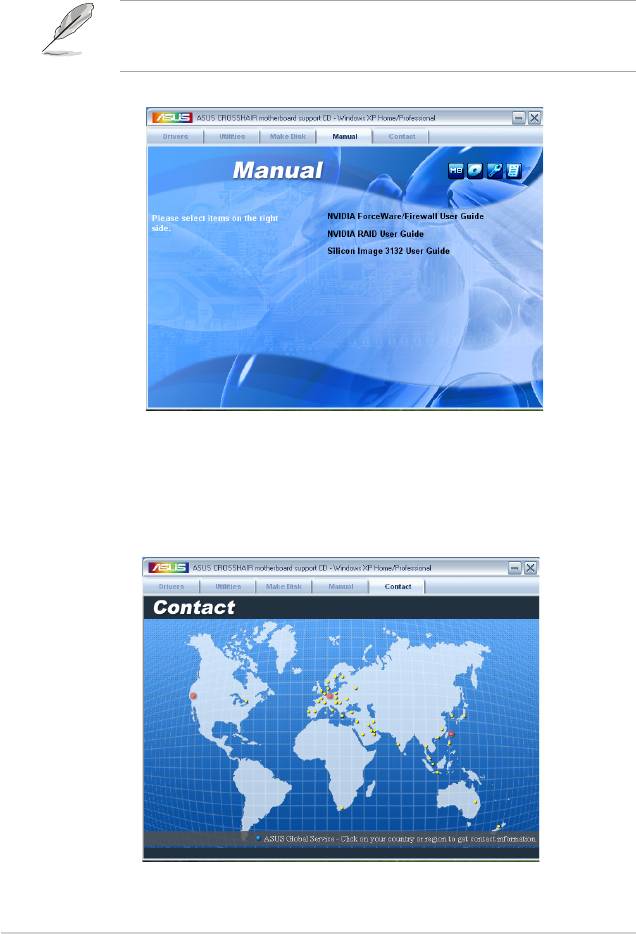
5.2.5 Manuals menu
The Manuals menu contains a list of supplementary user manuals. Click an item to
open the folder of the user manual.
Most user manual les are in Portable Document Format (PDF). Install the
®
®
Adobe
Acrobat
Reader from the Utilities menu before opening a user manual
le.
5.2.6 ASUS Contact information
Click the Contact tab to display the ASUS contact information. You can also nd
this information on the inside front cover of this user guide.
5-6
Chapter 5: Software support
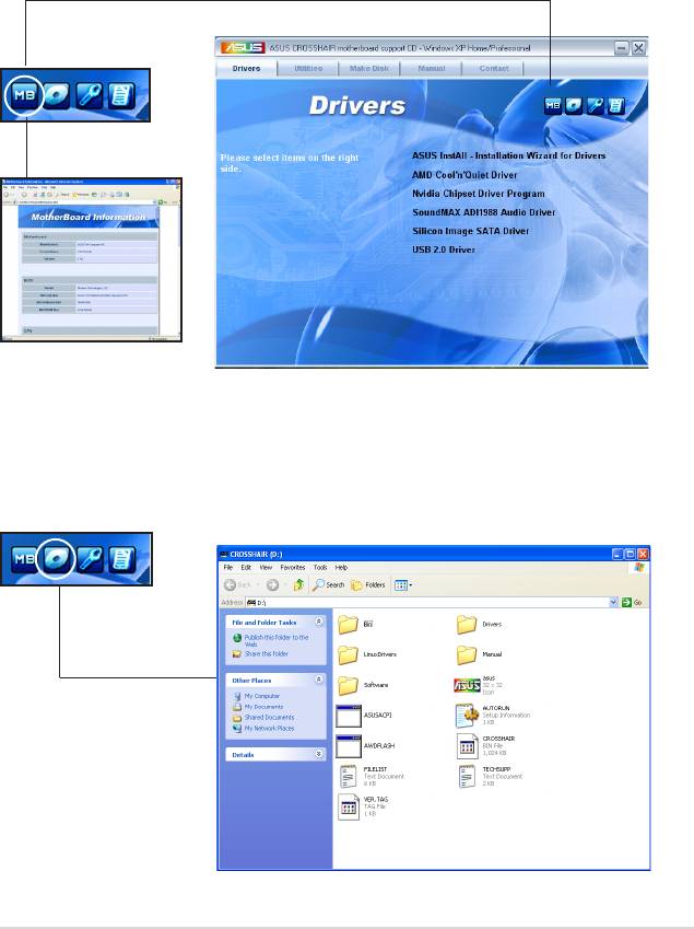
5.2.7 Other information
The icons on the top right corner of the screen give additional information on the
motherboard and the contents of the support DVD. Click an icon to display the
specied information.
Motherboard Info
Displays the general specications of the motherboard.
Browse this DVD
Displays the support DVD contents in graphical format.
ASUS Crosshair
5-7
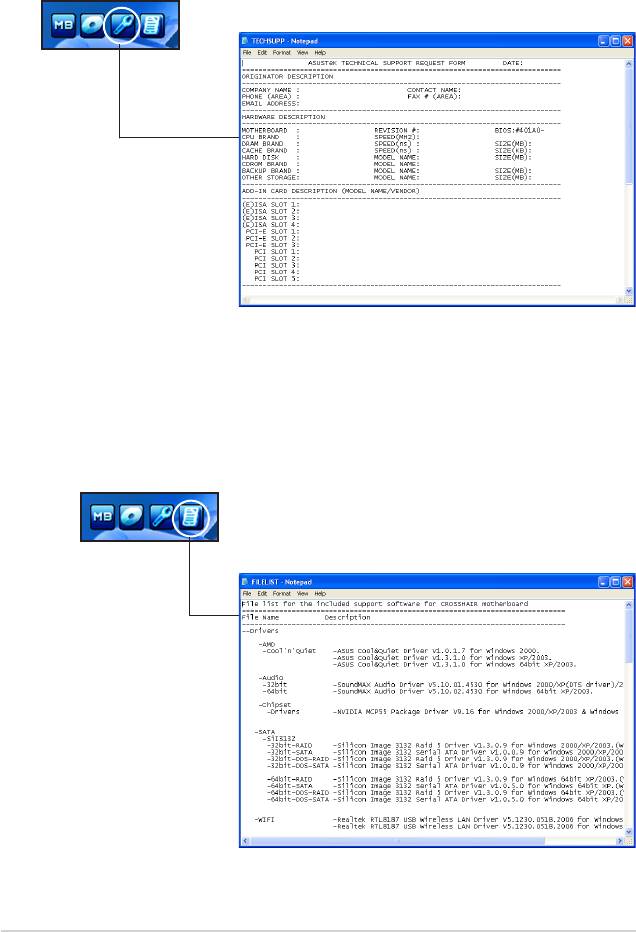
Technical support Form
Displays the ASUS Technical Support Request Form that you have to ll out when
requesting technical support.
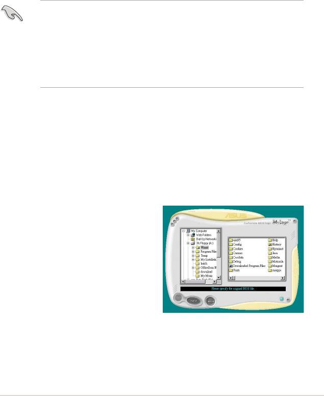
Filelist
Displays the contents of the support DVD and a brief description of each in text
format.
5-8
Chapter 5: Software support
5.3 Software information
Most of the applications in the support DVD have wizards that will conveniently
guide you through the installation. View the online help or readme le that came
with the software application for more information.
5.3.1 ASUS MyLogo3™
The ASUS MyLogo3™ utility lets you customize the boot logo. The boot logo is the
image that appears on screen during the Power-On Self-Tests (POST). The ASUS
MyLogo3™ is automatically installed when you install the ASUS Update utility from
the support DVD. See section “5.2.3 Utilities menu” for details.
• Before using the ASUS MyLogo3™, use the Award BIOS Flash utility to
make a copy of your original BIOS le, or obtain the latest BIOS version
from the ASUS website. See section “4.1.4 Updating the BIOS.”
• Make sure that the BIOS item Full Screen Logo is set to [Enabled]
if you wish to use ASUS MyLogo2. See section “4.6.5 Boot Settings
Conguration”.
• You can create your own boot logo image in GIF, JPG, or BMP le formats.
To launch the ASUS MyLogo3™:
1. Launch the ASUS Update utility. Refer to section “4.1.1 ASUS Update utility”
for details.
2. Select Options from the drop down menu, then click Next.
3. Check the option Launch MyLogo to replace system boot logo before ashing
BIOS, then click Next.
4. Select Update BIOS from a le from the drop down menu, then click Next.
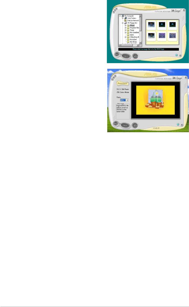
5. When prompted, locate the new BIOS le, then click Next. The ASUS
MyLogo window appears.
6. From the left window pane, select the
folder that contains the image you
intend to use as your boot logo.
ASUS Crosshair
5-9
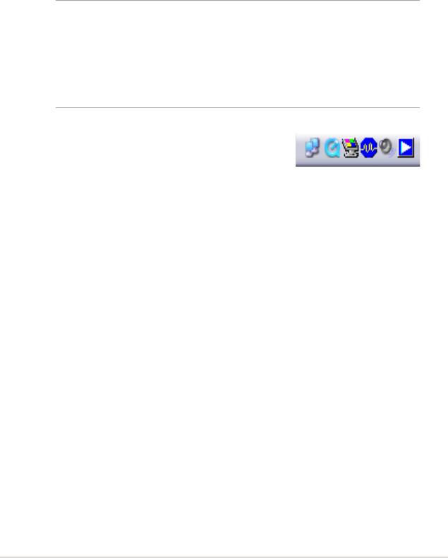
7. When the logo images appear on the
right window pane, select an image to
enlarge by clicking on it.
8. Adjust the boot image to your desired
size by selecting a value on the Ratio
box.
9. When the screen returns to the ASUS Update utility, ash the original BIOS to
load the new boot logo.
10. After ashing the BIOS, restart the computer to display the new boot logo
during POST.
5-10
Chapter 5: Software support
®
5.3.2 SoundMAX
High Denition Audio utility
The ADI AD1988B High Denition Audio CODEC provides 8-channel audio
®
capability through the SoundMAX
audio utility with AudioESP™ software to
deliver the ultimate audio experience on your PC. The software implements high
quality audio synthesis/rendering, 3D sound positioning, and advanced voice-input
technologies.
Follow the installation wizard to install the ADI AD1988B Audio Driver from the
®
support DVD that came with the motherboard package to activate the SoundMAX
audio utility.
•
You must use 4-channel, 6-channel or 8-channel speakers for this setup.
®
®
®
• SoundMAX
requires Microsoft
Windows
2000/XP or later version. Make
sure that one of these operating systems is installed before installing
®
SoundMAX
.
• Jack Retasking function works on High Denition front panel audio ports
only.
®
If the SoundMAX
audio utility is correctly installed, you
®
will nd the SoundMAX
icon on the taskbar.
ASUS Crosshair
5-11
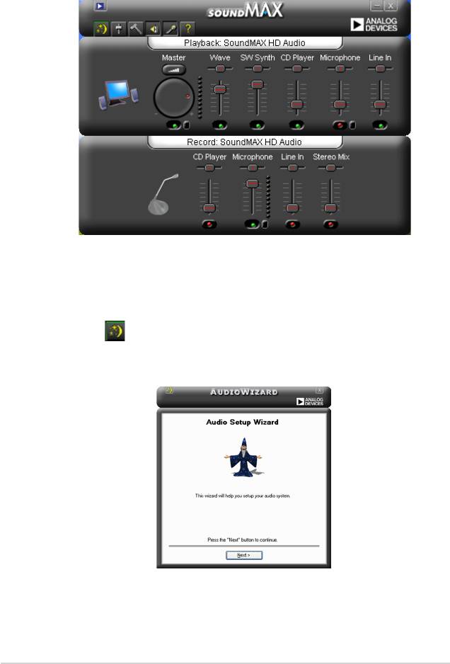
®
®
From the taskbar, double-click on the SoundMAX
icon to display the SoundMAX
Control Panel.
Audio Setup Wizard
®
By clicking the icon from the SoundMAX
control panel, you can easily
congure your audio settings. Simply follow succeeding screen instructions and
begin enjoying High Denition Audio.
5-12
Chapter 5: Software support
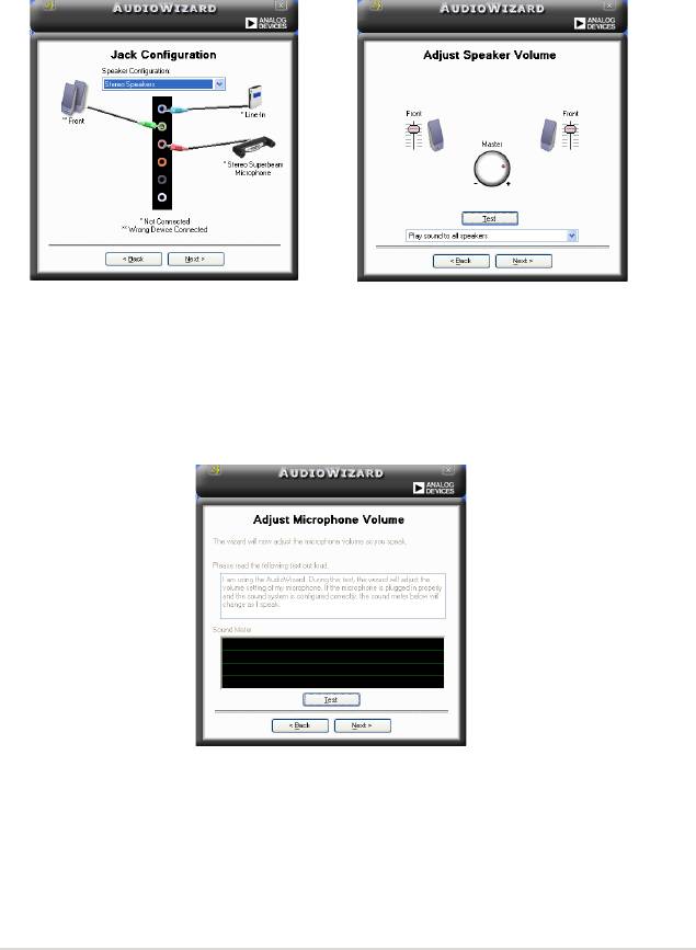
Jack conguration
Adjust speaker volume
This screen helps you congure your
This screen helps you adjust speaker
computer’s audio ports, depending on
volume. Click the Test button to hear
the audio devices you have installed.
the changes you have made.
Adjust microphone volume
This screen helps you adjust microphone volume. You will be asked to read pre-
written text to allow the AudioWizard to adjust the volume as you speak.
ASUS Crosshair
5-13
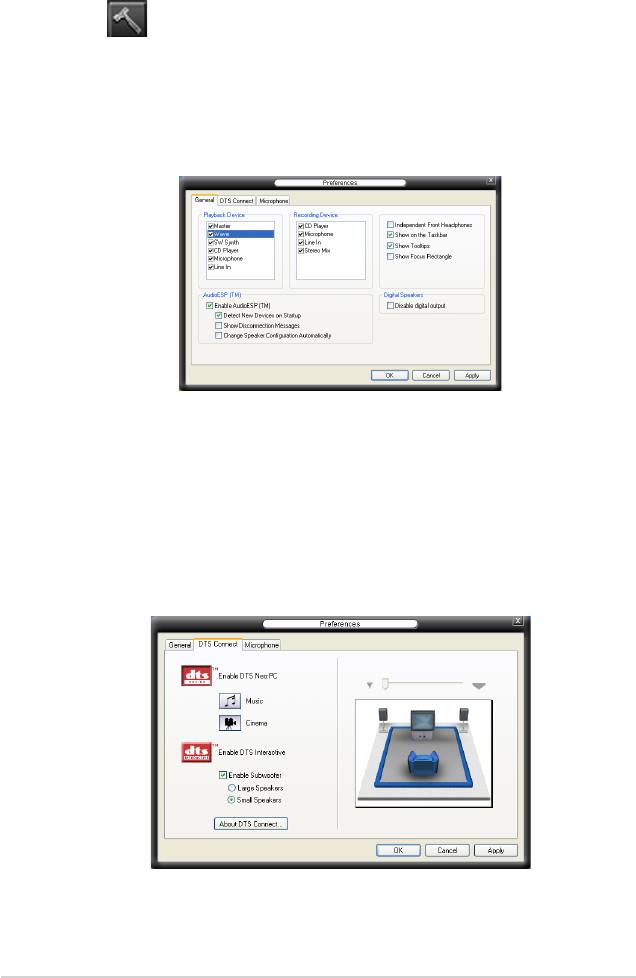
Audio preferences
Click the icon to go to the Preferences page. This page allows you to change
various audio settings.
General options
Click the General tab to choose your playback and recording devices, enable/
disable the AudioESP™ feature, and enable/disable digital output.
DTS.
This feature is consists of two elements: DTS interactive and DTS NEO:PC. DTS
interactive re-encodes your stereo or multi-channel sound into a DTS audio signal
and send it out from your PC to any DTS enabled system.
While DTS NEO:PC turns your stereo audio such as MP3, WMA, CD, and other
sound format into a convincing multi-channel audio experience.
5-14
Chapter 5: Software support
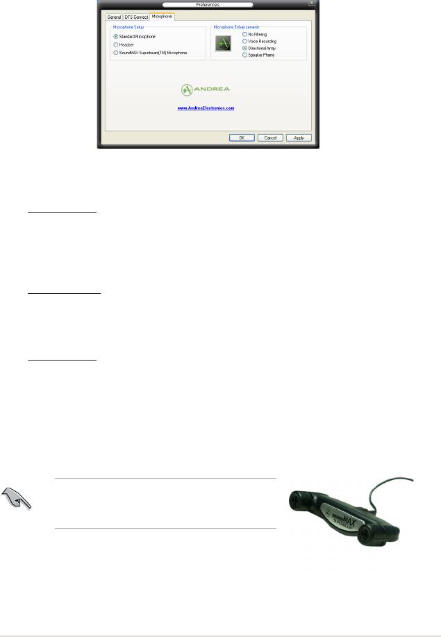
Microphone options
Click the Listening Environment tab allows you to optimize your microphone input
settings.
Enhanced Microphone Features
Voice recording
Enables Noise Filter function. Detects repetitive and stationary noises like
computer fans, air conditioners, and other background noises then eliminates
it in the incoming sudio stream while recording. You can enable it for a better
recording quality.
Directional Array
Receives only the sound coming from the reception cone and eliminates
interferences including neighboring speakers and reverberations. You can
enable it to transit clearer sound during on-line games, MSN, or Skype.
Speaker Phone
Advanced de-reverberation techniques can help to reduce echo and minimize
its effect on the speech engine. You can enable it when you have conference
call to reduce echoes in the other side.
The directional Array and Speaker Phone
function only when working with the ASUS Array
Mic.
ASUS Crosshair
5-15
5.3.3 Cool ‘n’ Quiet!™ Technology
The motherboard supports the AMD Cool ‘n’ Quiet!™ Technology that dynamically
and automatically change the CPU speed, voltage, and amount of power
depending on the task the CPU performs.
Enabling Cool ‘n’ Quiet!™ Technology
To enable Cool ‘n’ Quiet!™ Technology:
1. Turn on the system and enter BIOS by pressing the <Del> key during the
Power On Self-Tests (POST).
2. Go to Extreme -> AMD Cool ‘n’Quiet function and set it to [Enabled]. See
section “4.4 Extreme Menu.”
3. Save your changes and exit BIOS Setup.
4. Reboot your computer and set your Power Option Properties depending on
your operating system.
Windows® 2000/XP
1. From the Windows® 2000/XP operating system, click the Start button. Select
Settings, then Control Panel.
2. Make sure the Control Panel is set to Classic View.
3. Double-click the Display icon in the Control Panel then select the Screen
Saver tab.
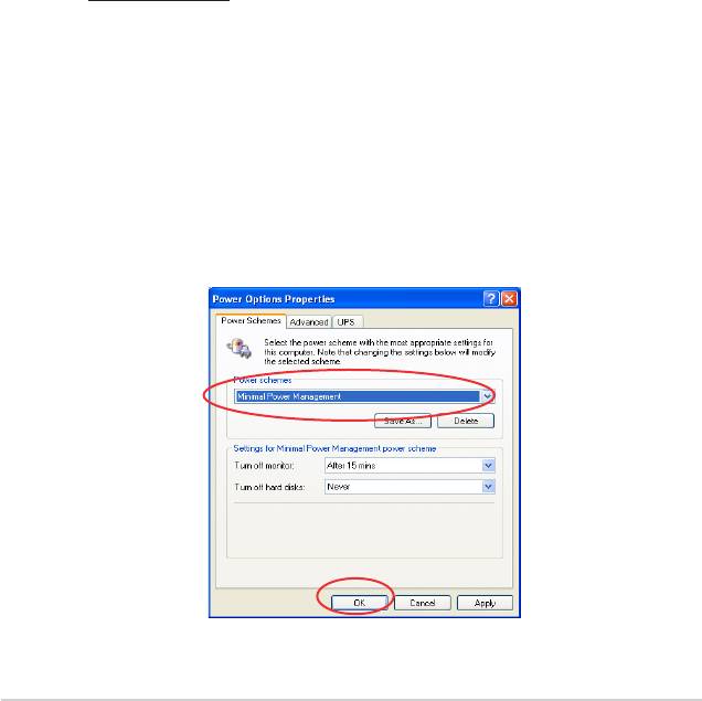
4. Click the Power button. The following dialog box appears.
5. From the Power schemes combo list box, select Minimal Power
Management.
6. Click OK to effect settings.
5-16
Chapter 5: Software support
• Make sure to install the AMD Cool ‘n’ Quiet!™ driver and application before
using this feature.
• The AMD Cool ‘n’ Quiet!™ technology feature works only with the AMD
heatsink and fan assembly with monitor chip
• If you purchased a separate heatsink and fan package, use the ASUS
Q-Fan technology feature to automatically adjust the CPU fan speed
according to your system loading.
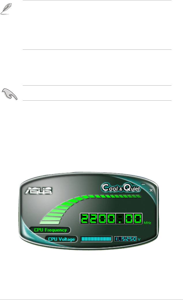
Launching the Cool ‘n’ Quiet!™ software
The motherboard support DVD includes the Cool ‘n’ Quiet!™ software that enables
you to view your system’s real-time CPU Frequency and voltage.
Make sure to install the Cool ‘n’ Quiet!™ software from the motherboard support
DVD. Refer to section “5.2.3 Utilities menu” for details.
To launch the Cool ‘n’ Quiet!™ program:
1. If you are using Windows® 2000, click the Start button. Select Programs->
ASUS -> Cool & Quiet -> Cool & Quiet.
2. If you are using Windows® XP, click the Start button. Select All Programs->
ASUS -> Cool & Quiet -> Cool & Quiet.
3. The Cool ‘n’ Quiet!™ technology screen appears and displays the current
CPU Frequency and CPU Voltage.
ASUS Crosshair
5-17
5.3.4 ASUS PC Probe II
PC Probe II is a utility that monitors the computer’s vital components, and detects
and alerts you of any problem with these components. PC Probe II senses fan
rotations, CPU temperature, and system voltages, among others. Because PC
Probe II is software-based, you can start monitoring your computer the moment
you turn it on. With this utility, you are assured that your computer is always at a
healthy operating condition.
Installing PC Probe II
To install PC Probe II on your computer:
1. Place the support DVD to the optical drive. The Drivers installation tab
appears if your computer has an enabled Autorun feature.
If Autorun is not enabled in your computer, browse the contents of the support
DVD to locate the setup.exe le from the ASUS PC Probe II folder. Double-click
the setup.exe le to start installation.
2. Click the Utilities tab, then click ASUS PC Probe II.
3. Follow the screen instructions to complete installation.
Launching PC Probe II
You can launch the PC Probe II right after installation or anytime from the
®
Windows
desktop.
®
To launch the PC Probe II from the Windows
desktop, click Start > All Programs
> ASUS > PC Probe II > PC Probe II v1.00.43. The PC Probe II main window
appears.
®
After launching the application, the PC Probe II icon appears in the Windows
taskbar. Click this icon to close or restore the application.
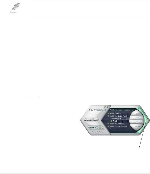
Using PC Probe II
Main window
The PC Probe II main window allows you to view the current status of your
system and change the utility
conguration. By default, the main
window displays the Preference
section. You can close or restore
the Preference section by clicking
on the triangle on the main
window right handle.
Click to close the
Preference panel
5-18
Chapter 5: Software support
Button Function
Opens the Conguration window
Opens the Report window
Opens the Desktop Management Interface window
Opens the Peripheral Component Interconnect window
Opens the Windows Management Instrumentation window
Opens the hard disk drive, memory, CPU usage window
Shows/Hides the Preference section
Minimizes the application
Closes the application
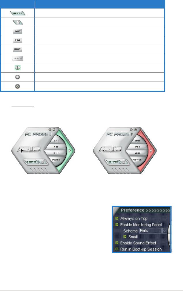
Sensor alert
When a system sensor detects a problem, the main window right handle
turns red, as the illustrations below show.
When displayed, the monitor panel for that sensor also turns red. Refer to the
Monitor panels section for details.
Preferences
You can customize the application using the
Preference section in the main window. Click
the box before each preference to activate or
deactivate.
ASUS Crosshair
5-19
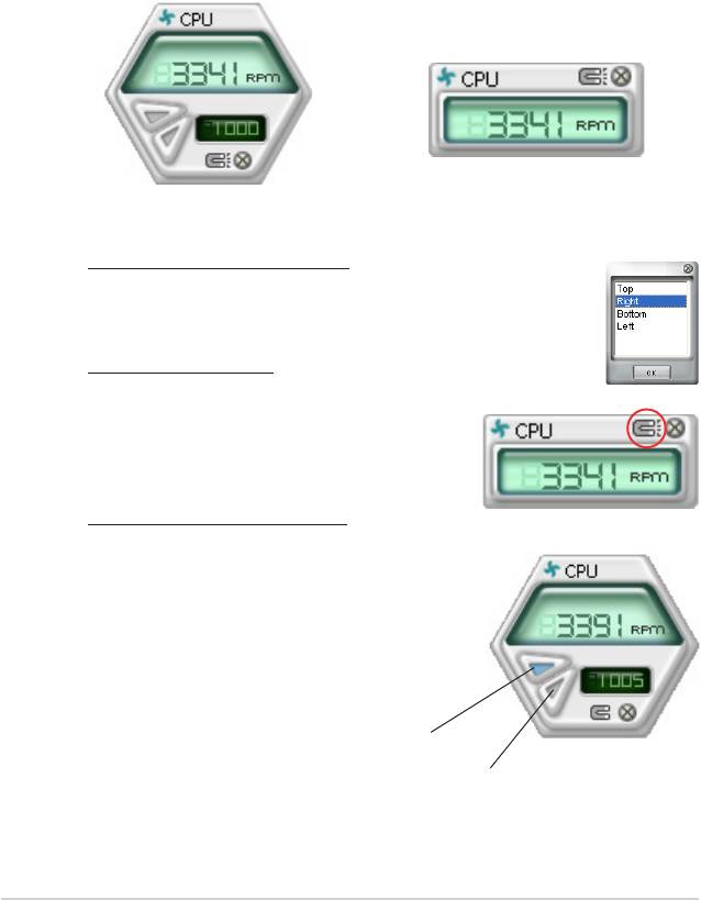
Hardware monitor panels
The hardware monitor panels display the current value of a system sensor such as
fan rotation, CPU temperature, and voltages.
The hardware monitor panels come in two display modes: hexagonal (large) and
rectangular (small). When you check the Enable Monitoring Panel option from the
Preference section, the monitor panels appear on your computer’s desktop.
Small display
Large display
Changing the monitor panels position
To change the position of the monitor panels in the desktop,
click the arrow down button of the Scheme options, then select
another position from the list box. Click OK when nished.
Moving the monitor panels
All monitor panels move together using a magnetic effect. If
you want to detach a monitor panel from
the group, click the horseshoe magnet
icon. You can now move or reposition the
panel independently.
Adjusting the sensor threshold value
You can adjust the sensor threshold value in the monitor panel
by clicking the <+> or <-> buttons. You can also
adjust the threshold values using the Cong
window.
You cannot adjust the sensor threshold values in a small
monitoring panel.
Click to
increase value
Click to
decrease
value
5-20
Chapter 5: Software support
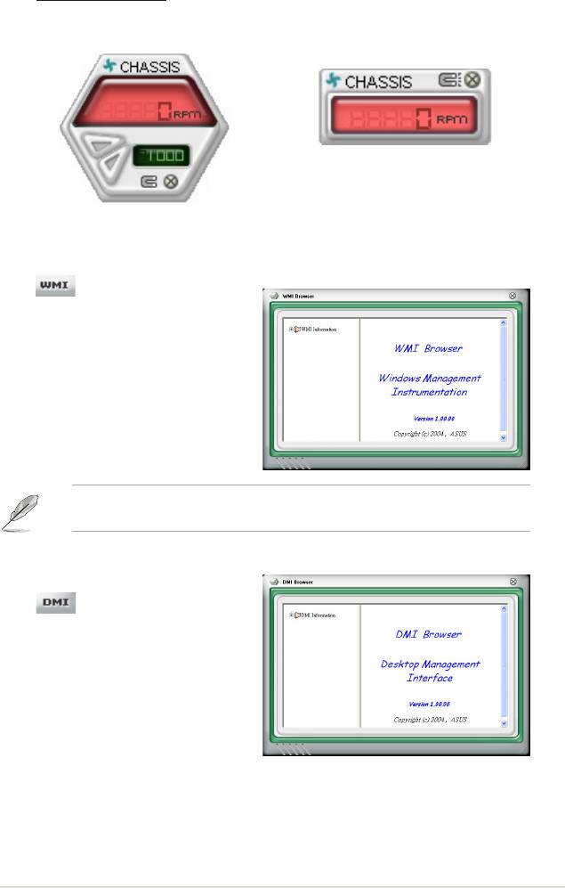
Monitoring sensor alert
The monitor panel turns red when a component value exceeds or is lower
than the threshold value. Refer to the illustrations below.
Small display
Large display
WMI browser
Click to display the
WMI (Windows Management
Instrumentation) browser. This
®
browser displays various Windows
management information. Click an
item from the left panel to display on
the right panel. Click the plus sign (+)
before WMI Information to display the
available information.
You can enlarge or reduce the browser size by dragging the bottom right corner
of the browser.
DMI browser
Click to display the DMI
(Desktop Management Interface)
browser. This browser displays various
desktop and system information.
Click the plus sign (+) before DMI
Information to display the available
information.
ASUS Crosshair
5-21
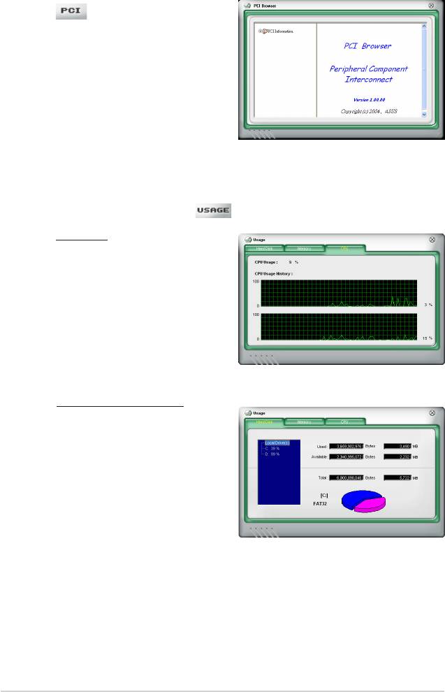
PCI browser
Click to display the PCI
(Peripheral Component Interconnect)
browser. This browser provides
information on the PCI devices installed
on your system. Click the plus sign
(+) before the PCI Information item to
display available information.
Usage
The Usage browser displays real-time information on the CPU, hard disk drive
space, and memory usage. Click to display the Usage browser.
CPU usage
The CPU tab displays real-
time CPU usage in line graph
representation. If the CPU has
an enabled Hyper-Threading,
two separate line graphs display
the operation of the two logical
processors.
Hard disk drive space usage
The Hard Disk tab displays the
used and available hard disk
drive space. The left panel of the
tab lists all logical drives. Click
a hard disk drive to display the
information on the right panel.
The pie chart at the bottom of
the window represents the used
(blue) and the available HDD
space.
5-22
Chapter 5: Software support
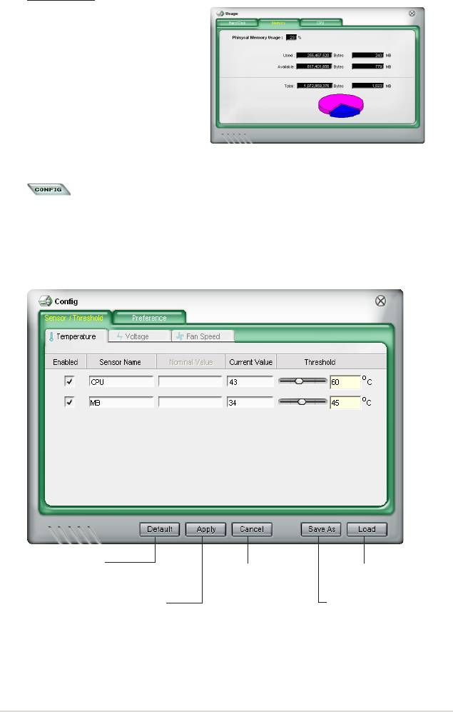
Memory usage
The Memory tab shows both
used and available physical
memory. The pie chart at the
bottom of the window represents
the used (blue) and the available
Conguring PC Probe II
Click to view and adjust the sensor threshold values.
The Cong window has two tabs: Sensor/Threshold and Preference. The Sensor/
Threshold tab enables you to activate the sensors or to adjust the sensor threshold
values. The Preference tab allows you to customize sensor alerts, or change the
temperature scale.
Loads the default
threshold values for
Cancels or
Loads your saved
each sensor
ignores your
conguration
changes
Applies your
Saves your
changes
conguration
ASUS Crosshair
5-23

5.4 RAID congurations
®
The motherboard comes with the Silicon Image Sil3132 and the NVIDIA
nForce™
590- SLI Southbridge RAID controllers that allow you to congure Serial ATA
hard disk drives as RAID sets. The motherboard supports the following RAID
congurations.
RAID 0
(Data striping)
optimizes two identical hard disk drives to read and write
data in parallel, interleaved stacks. Two hard disks perform the same work as a
single drive but at a sustained data transfer rate, double that of a single disk alone,
thus improving data access and storage. Use of two new identical hard disk drives
is required for this setup.
RAID 1
(Data mirroring)
copies and maintains an identical image of data from one
drive to a second drive. If one drive fails, the disk array management software
directs all applications to the surviving drive as it contains a complete copy of
the data in the other drive. This RAID conguration provides data protection and
increases fault tolerance to the entire system. Use two new drives or use an
existing drive and a new drive for this setup. The new drive must be of the same
size or larger than the existing drive.
RAID 0+1 is data striping and data mirroring combined without parity (redundancy
data) having to be calculated and written. With the RAID 0+1 conguration you get
all the benets of both RAID 0 and RAID 1 congurations. Use four new hard disk
drives or use an existing drive and three new drives for this setup.
RAID 5 stripes both data and parity information across three or more hard
disk drives. Among the advantages of RAID 5 conguration include better
HDD performance, fault tolerance, and higher storage capacity. The RAID
5 conguration is best suited for transaction processing, relational database
applications, enterprise resource planning, and other business systems. Use a
minimum of three identical hard disk drives for this setup.
RAID 10 is a striped conguration with each stripe a RAID 1 array of drives. It
combines the features of both RAID 1 and RAID 0. Fault tolerance is provided
through mirroring while adding performance through striping. This offers higher
performance than a RAID 1 conguration but at a much higher cost. A minimum of
four hard disk drives is required for this setup.
JBOD
(Spanning)
stands for Just a Bunch of Disks and refers to hard disk drives
that are not yet congured as a RAID set. This conguration stores the same
data redundantly on multiple disks that appear as a single disk on the operating
system. Spanning does not deliver any advantage over using separate disks
independently and does not provide fault tolerance or other RAID performance
benets.
5-24
Chapter 5: Software support

If you want to boot the system from a hard disk drive included in a RAID set,
copy rst the RAID driver from the support DVD to a oppy disk before you
install an operating system to a selected hard disk drive. Refer to section “5.5
Creating a RAID driver disk” for details.
®
5.4.1 NVIDIA
RAID congurations
The motherboard includes a high performance SATA RAID controller integrated in
®
the NVIDIA
nForce™ 590-SLI southbridge chipset. It supports RAID 0, RAID 1,
RAID 0+1, RAID 5 and JBOD for six independent Serial ATA channels.
Installing Serial ATA (SATA) hard disks
The motherboard supports Ultra DMA 133/100/66 and Serial ATA hard disk drives.
For optimal performance, install identical drives of the same model and capacity
when creating a disk array.
To install the SATA hard disks for a RAID conguration:
1. Install the SATA hard disks into the drive bays.
2. Connect the SATA signal cables.
3. Connect a SATA power cable to the power connector on each drive.
Refer to the RAID controllers user manual in the motherboard support DVD for
detailed information on RAID congurations. See section “5.2.5 Manuals menu.”
Setting the BIOS RAID items
After installing the hard disk drives, make sure to set the necessary RAID items in
the BIOS before setting your RAID conguration.
To set the BIOS RAID items:
1. Boot the system and press <Del> during the Power-On Self-Test (POST) to
enter the BIOS Setup Utility.
2. Enable the RAID Enabled item in the BIOS. See section “4.5.4 Onboard
Device Conguration > Serial-ATA Conguration” for details.
3. Select and enable the IDE or SATA drive(s) that you want to congure
as RAID. See section “4.5.4 Onboard Device Conguration > Serial-ATA
Conguration” for details.
4. Save your changes and Exit Setup.
Make sure to re-enter your NVRAID settings after the CMOS is cleared;
otherwise, the system will not recognize your RAID setup.
• For detailed descriptions on the NVIDIA® RAID conguration, refer to the
®
“NVIDIA
RAID User’s Manual” found in your motherboard support DVD.
• When using Windows 2000 operating system, make sure to install the
Windows 2000 Service Pack 4 or later versions.
ASUS Crosshair
5-25
®
Entering the NVIDIA
RAID utility
®
To enter the NVIDIA
RAID utility:
1. Boot up your computer.
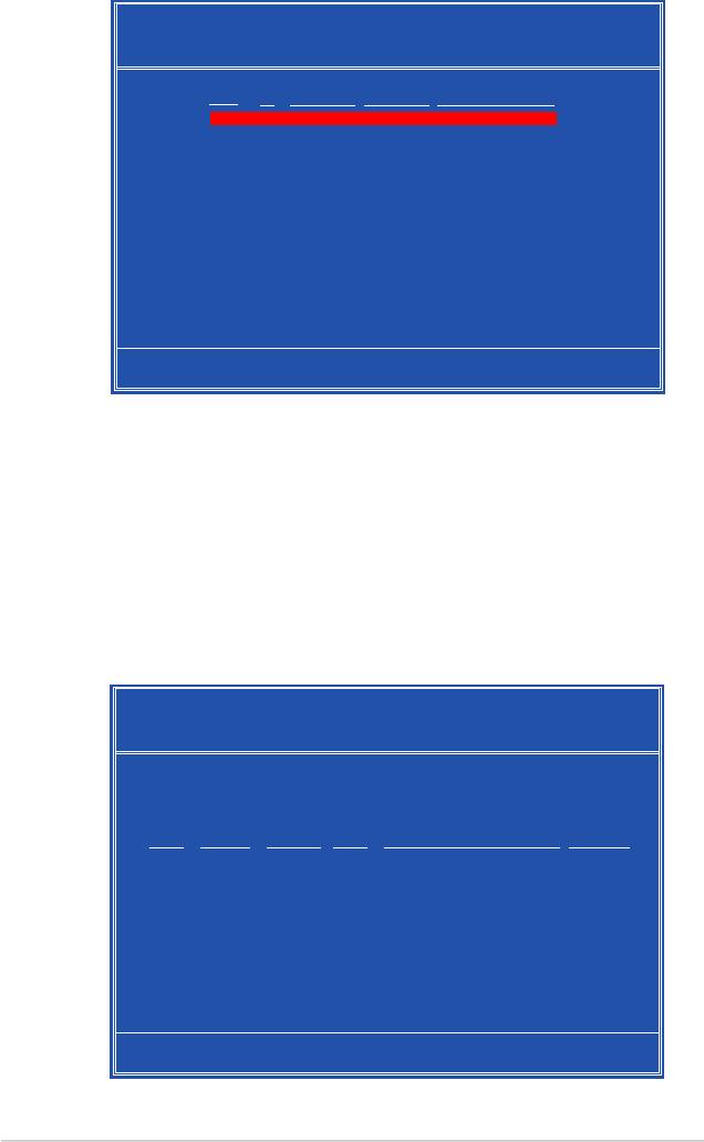
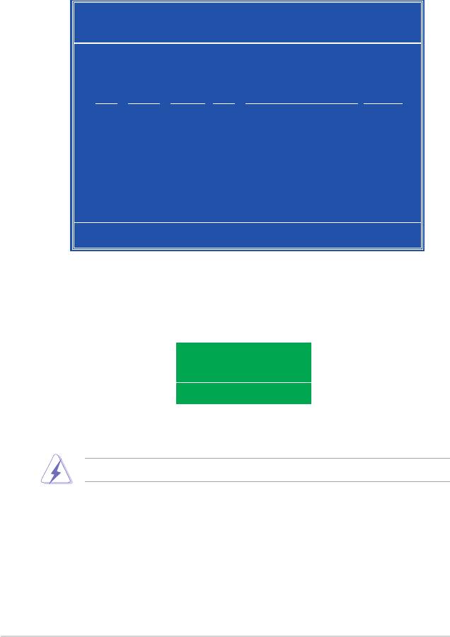
2. During POST, press <F10> to display the main menu of the utility.
The RAID BIOS setup screens shown in this section are for reference only, and
may not exactly match the items on your screen.
NVIDIA RAID Utility Oct 5 2004
- Dene a New Array -
RAID Mode: Striping Striping Block: Optimal
Free Disks Array Disks
Loc Disk Model Name Loc Disk Model Name
1.0.M XXXXXXXXXXXXXXXXXX
1.1.M XXXXXXXXXXXXXXXXXX [→] Add
2.0.M XXXXXXXXXXXXXXXXXX
2.1.M XXXXXXXXXXXXXXXXXX
[←] Del
[F6] Back [F7] Finish [TAB] Navigate [↑↓] Select [ENTER] Popup
At the bottom of the screen are the navigation keys. These keys allow you to move
through and select menu options.
Creating a RAID Volume
To create a RAID volume:
®
1. From the NVIDIA
RAID utility Dene a New Array menu, select RAID Mode
then press <Enter>. The following submenu appears.
Use the up or down arrow keys to select a
Mirroring
RAID mode then press <Enter>.
Striping
Stripe Mirroring
Spanning
5-26
Chapter 5: Software support
2. Press <TAB> select the Striping
8K ↑
Block then press <Enter>. The
16K
32K
following submenu appears:
64K
128K
Optim↓
If you selected Striping or Stripe Mirroring, use the up or down arrow keys to
select the stripe size for your RAID 0 array then press <Enter>.The available
values range from 8 KB to 128 KB. The default selection is 128 KB. The strip
value should be chosen based on the planned drive usage.
• 8 /16 KB - low disk usage
• 64 KB - typical disk usage
• 128 KB - performance disk usage
TIP: For server systems, we recommend using a lower array block size. For
multimedia computer systems used mainly for audio and video editing, we
recommend a higher array block size for optimum performance.
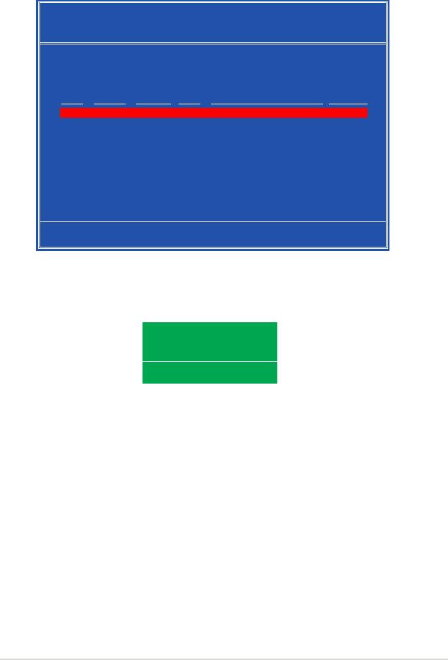
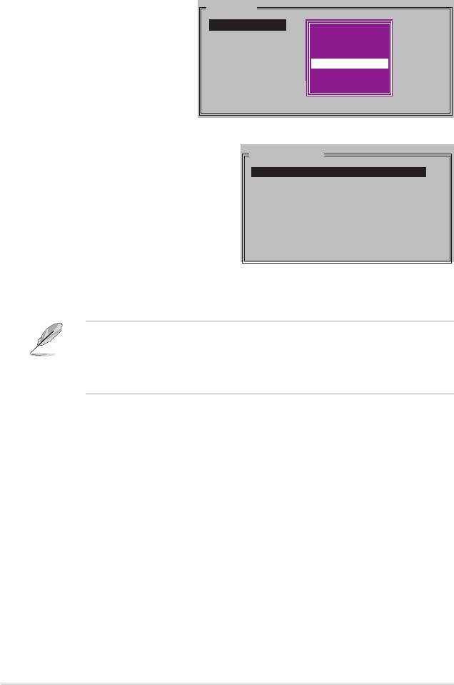
3.` Press <TAB> to select the Free Disks area. Use the left or right arrow keys to
assign the array disks.
4. Press <F7> to create RAID set. The following message box appears.
Clear disk data?
[Y] YES [N] NO
5. Press <Y> to clear the selected disks or <N> to proceed without clearing the
disks. The following screen appears.
Take caution in using this option. All data on the RAID drives will be lost!
ASUS Crosshair
5-27
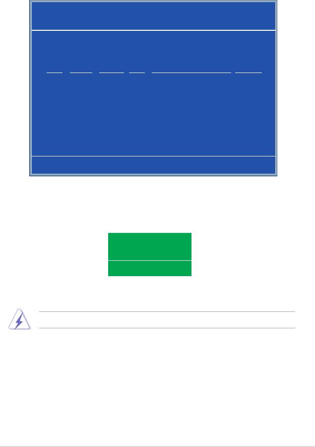
NVIDIA RAID Utility Oct 5 2004
- Array List -
Boot Id Status Vendor Array Model Name
No 4 Healthy NVIDIA MIRROR XXX.XXG
[Ctrl-X]Exit [↑↓]Select [B]Set Boot [N]New Array [ENTER]Detail
A new set of navigation keys is displayed on the bottom of the screen.
6. Press <Ctrl+X> to save settings and exit.
Rebuilding a RAID array
To rebuild a RAID array:
1. From the Array List menu, use the up or down arrow keys to select a RAID
array then press <Enter>. The RAID Array details appear.
Array 1 : NVIDIA MIRROR XXX.XXG
- Array Detail -
RAID Mode: Mirroring
Striping Width: 1 Striping Block: 64K
Adapt Channel M/S Index Disk Model Name Capacity
2 1 Master 0 XXXXXXXXXXXXXXXXX XXX.XXGB
1 0 Master 1 XXXXXXXXXXXXXXXXX XXX.XXGB
[R] Rebuild [D] Delete [C] Clear Disk [ENTER] Return
5-28
Chapter 5: Software support
A new set of navigation keys is displayed on the bottom of the screen.
2. Press <R> to rebuild a RAID array. The following screen appears.
Array 1 : NVIDIA MIRROR XXX.XXG
- Select Disk Inside Array -
RAID Mode: Mirroring
Striping Width: 1 Striping Block: 64K
Adapt Channel M/S Index Disk Model Name Capacity
2 1 Master 0 XXXXXXXXXXXXXXXXX XXX.XXGB
1 0 Master 1 XXXXXXXXXXXXXXXXX XXX.XXGB
[↑↓] Select [F6] Back [F7] Finish
3. Use the up or down arrow keys to select a RAID array to rebuild, then press
<F7>. The following conrmation message appears.
Rebuild array?
[ENTER] OK [ESC] Cancel
4. Press <Enter> to start rebuilding array or press <Esc> to cancel.
5. After the rebuild process, the Array list menu appears.
ASUS Crosshair
5-29
Deleting a RAID array
To delete a RAID array:
1. From the Array List menu, use the up or down arrow keys to select a RAID
array then press <Enter>. The RAID Array details appear.
Array 1 : NVIDIA MIRROR XXX.XXG
- Array Detail -
RAID Mode: Mirroring
Striping Width: 1 Striping Block: 64K
Adapt Channel M/S Index Disk Model Name Capacity
2 1 Master 0 XXXXXXXXXXXXXXXXX XXX.XXGB
1 0 Master 1 XXXXXXXXXXXXXXXXX XXX.XXGB
[R] Rebuild [D] Delete [C] Clear Disk [ENTER] Return
A new set of navigation keys is displayed on the bottom of the screen.
2. Press <D> to delete a RAID array. The following conrmation message
appears.
Delete this array?
[Y] YES [N] No
3. Press <Y> to delete array or press <N> to cancel.
Take caution in using this option. All data on the RAID drives will be lost!
4. If you selected Yes, the Dene a New Array menu appears.
5-30
Chapter 5: Software support
Clearing a disk data
To clear disk data:
1. From the Array List menu, use the up or down arrow keys to select a RAID
array then press <Enter>. The RAID Array details appear.
Array 1 : NVIDIA MIRROR XXX.XXG
- Array Detail -
RAID Mode: Mirroring
Striping Width: 1 Striping Block: 64K
Adapt Channel M/S Index Disk Model Name Capacity
2 1 Master 0 XXXXXXXXXXXXXXXXX XXX.XXGB
1 0 Master 1 XXXXXXXXXXXXXXXXX XXX.XXGB
[R] Rebuild [D] Delete [C] Clear Disk [ENTER] Return
A new set of navigation keys is displayed on the bottom of the screen.
2. Press <C> to clear disk. The following conrmation message appears.
Clear disk data?
[Y] YES [N]
5. Press <Y> to clear the disk data or press <N> to cancel.
Take caution in using this option. All data on the RAID drives will be lost!
ASUS Crosshair
5-31
5.4.2 Silicon Image RAID congurations
The Silicon Image RAID controller supports RAID 0 and RAID 1 congurations. Use
the Silicon Image RAID utility to congure a disk array.
Installing External Serial ATA (E-SATA) hard disks
To install the External SATA hard disks for a RAID conguration:
1. Connect one end of the E-SATA signal cables to the rear panel port.
2. Connect the other end of the E-SATA signal cables to the external SATA disk
drives.
The installation procedure in this section is provided for reference only, refer
to the user’s manual that comes with the external drive for detailed installation
instructions.
Setting the BIOS RAID items
After installing the hard disk drives, make sure to set the necessary RAID items in
the BIOS before setting your RAID conguration.
To set the BIOS RAID items:
1. Boot the system and press <Del> during the Power-On Self-Test (POST) to
enter the BIOS Setup Utility.
2. From the Advanced > Onboard Device Conguration menu item in the BIOS
set the Silicon SATA II Controller item to RAID Mode. See section “4.5.4
Onboard Device Conguration” for details.
3. Save your changes and Exit Setup.
Launching the Silicon Image Array Management Software
®
Launch the Silicon Image Array Management software from Windows
XP by
clicking the Start button and selecting All Programs > Silicon Image > Sam
For details on the Silicon Image SATARaid™ RAID conguration, refer to the
“Sil3132 SATA RAID User’s Manual” in your motherboard support DVD.
5-32 Chapter 5: Software support
Entering the Silicon Image BIOS RAID Conguration Utility
To enter the Silicon Image BIOS RAID conguration utility:
1. Boot up your computer.
2. During POST, press <Ctrl+S> or <F4>.
The RAID BIOS setup screens shown in this section are for reference only, and
may not exactly match the items on your screen.
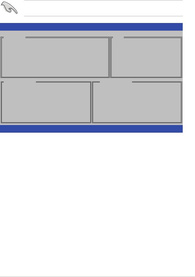
RAID Conguration Utility - Silicon Image Inc. Copyright (C) 2004
MAIN MENU
HELP
Create RAID set
Press “Enter” to create
Delete RAID set
RAID set
Rebuild Raid1 set
Resolve Conicts
Low Level Format
Logical Drive Info
PHYSICAL DRIVE
LOGICAL DRIVE
0 XXXXXXXXXXX XXXXXXMB
STXXXXXXXXX XXXXXXMB
1 XXXXXXXXXXX XXXXXXMB
STXXXXXXXXX XXXXXXMB
2 XXXXXXXXXXX XXXXXXMB
STXXXXXXXXX XXXXXXMB
3 XXXXXXXXXXX XXXXXXMB
STXXXXXXXXX XXXXXXMB
↑↓:Select Menu ESC:Previous Menu Enter:Select Ctrl-E:Exit
The Main Menu on the upper left corner allows you to select an operation to be
performed. The Main Menu options include the following:
Create RAID set - creates a new legacy RAID set or allocates spare drives.
Delete RAID set - deletes a RAID set or deallocates a spare drive.
Rebuild RAID1 set - rebuilds a RAID 1 set (e.g., swapped drives).
Resolve Conicts - automatically restores disrupted drives on a RAID set.
Low Level Format - creates a pattern of reference marks on a drive. Formatting the
disks erases all data previously stored in the drive.
Logical Drive Info -shows the current conguration of each RAID set.
On the upper right corner of the screen is the Help message box. The message
describes the function of each menu item. At the bottom of the screen is the
legend box. The keys on the legend box allow you to navigate through the setup
menu options. The following lists the keys found in the legend box and their
corresponding functions.
↑, ↓ : Select/Move to the next item
ESC : Previous Menu
Enter : Select
Ctrl-E : Exit
ASUS Crosshair 5-33
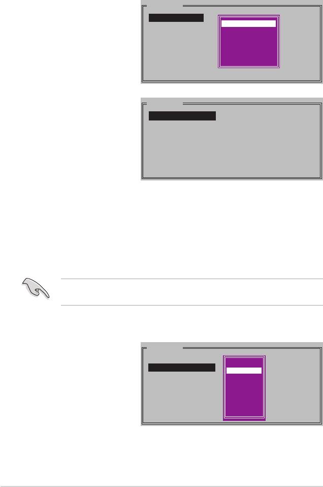
Creating a RAID 0 set (Striped)
To create a RAID set:
1. From the Silicon Image
MAIN MENU
conguration utility main
Create RAID set
menu, select Create RAID
Delete RAID set
RAID0
Rebuild Raid1 set
RAID1
set then press <Enter> to
Resolve Conicts
SPARE DRIVE
display an option menu.
Low Level Format
CONCATENATION
Logical Drive Info
2. Select RAID 0 then press
MAIN MENU
<Enter> to display the
Auto conguration
following.
Manual conguration
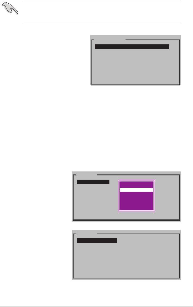
3. Select your desired method of conguration.
Auto conguration
a. Select Auto Conguration the press <Enter>.
b. The utility prompts a message to input the RAID size, use the up
or down arrow keys to set the RAID size then press <Enter>.
c. Press <Y> to conrm or <N> to return to the Main Menu.
By default, Auto conguration sets the stripe size to 64K and sets the logical
drives based on the physical drives installed.
Manual conguration
a. Select Manual
MAIN MENU
conguration and press
Auto conguration
chunk size
<Enter>. The following
Manual conguration
4K
pop-up menu appears.
8K
16K
b. Use the up or down
32K
arrow keys to select a
64K
128K
chunk size appropriate
to your drive usage then
press <Enter>.
5-34 Chapter 5: Software support
TIP: For server systems, we recommend using a lower array block size. For
multimedia computer systems used mainly for audio and video editing, we
recommend a higher array block size for optimum performance.
c. The selection bar moves to the
PHYSICAL DRIVE
Physical Drive menu Using the up
0 XXXXXXXXXXX XXXXXXMB
or down arrowkeys, select a drive
1 XXXXXXXXXXX XXXXXXMB
2 XXXXXXXXXXX XXXXXXMB
then press <Enter> to set the rst
3 XXXXXXXXXXX XXXXXXMB
drive of the RAID set.
d. Repeat step c to set the
second, third, and fourth drive. The
number of available drives depend
on the installed and enabled
physical drives in the system.
e. The utility prompts a message to input the RAID size, use the up or
down arrow keys to set the RAID size then press <Enter>.
f. Press <Y> to conrm or <N> to return to the Main Menu.
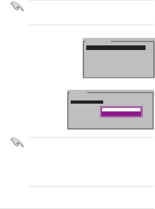
Creating a RAID 1 set (Mirrored)
To create a RAID 1 set:
1. From the Silicon Image
MAIN MENU
conguration utility main
Create RAID set
menu, select Create RAID
Delete RAID set
RAID0
RAID0
set then press <Enter>.
Rebuild Raid1 set
RAID1
RAID1
Resolve Conicts
SPARE DRIVE
RAID10
The following sub-menu
Low Level Format
CONCATENATION
SPARE DRIVE
appears.
Logical Drive Info
MAIN MENU
2. Select RAID 1 then press
<Enter> to display the
Auto conguration
Manual conguration
following.
ASUS Crosshair 5-35
3. Select your desired method of conguration.
Auto conguration
a. Select Auto Conguration then press <Enter>.
b. The utility prompts a message to input the RAID size, use the up
or down arrow keys to set the RAID size then press <Enter>.
c. Press <Y> to conrm or <N> to return to the Main Menu.
• Auto-conguration creates a RAID 1 set without a backup copy of the
current source disk data.
• When migrating a single hard disk drive to a RAID 1 set, use of the Manual
conguration is recommended.
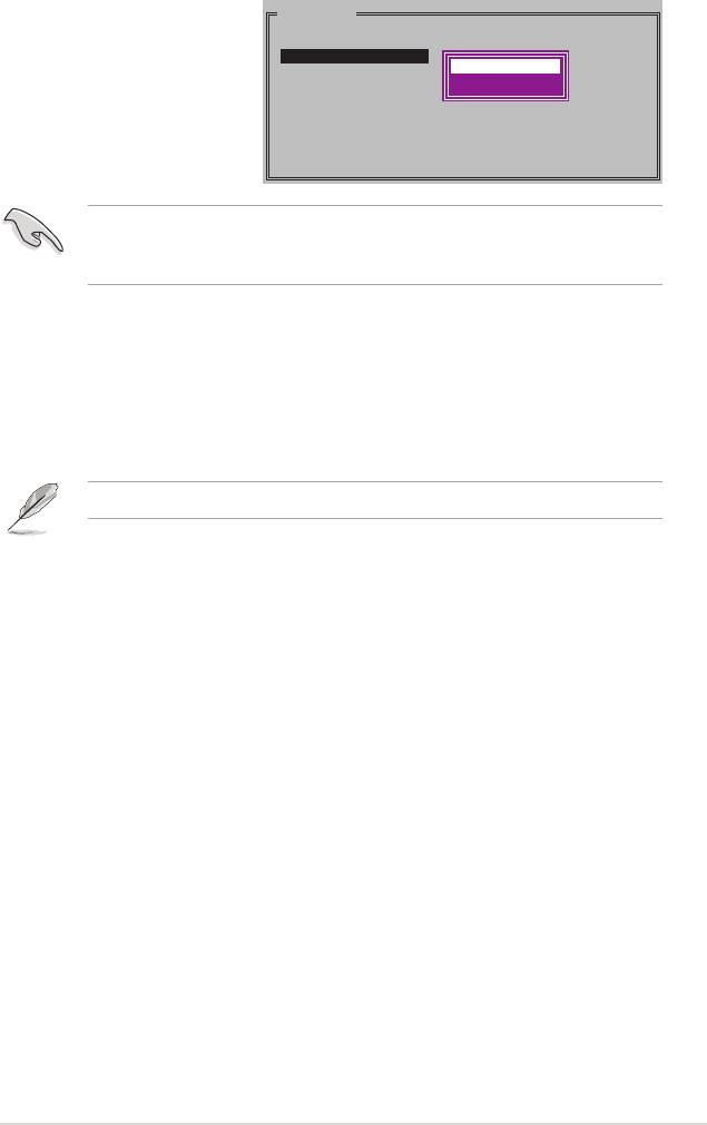
Manual conguration
a. Select Manual conguration
PHYSICAL DRIVE
and press <Enter>. The
0 XXXXXXXXXXX XXXXXXMB
1 XXXXXXXXXXX XXXXXXMB
selection bar moves to the
2 XXXXXXXXXXX XXXXXXMB
Physical Drives menu.
3 XXXXXXXXXXX XXXXXXMB
b. Using the up or down arrow
keys, select the source drive
and press <Enter>.
c. Repeat step b to
MAIN MENU
select the target drive.
Auto conguration
Manual conguration
d. After selecting the
source and target
Create with data copy
Create without data copy
drives, the following
pop-up menu appears.
• The Create with data copy option allows you to copy the current data from
the source drive to the mirror drive.
• Select Create with data copy if you have important data in your source
drive.
• The Create without data copy option disables the disk copy function of the
Mirrored set.
• If you selected Create without data copy, the RAID 1 set must be
repartitioned and reformatted to guarantee the consistency of its contents.
5-36 Chapter 5: Software support
e. If you selected Create
MAIN MENU
with data copy, the
Auto conguration
Manual conguration
following pop-up
online copy
ofine copy
menu appears.
The online copy option automatically copies the data to the target drives on the
background while writing to the source drives. The ofine copy option allows
you to copy the contents of the source drive to the target drives now.
f. Use the up or down arrow keys to select desired copy method, then
press <Enter>.
g. The utility prompts a message to input the RAID size, use the up or
down arrow keys to set the RAID size then press <Enter>.
h. Press <Y> to conrm or <N> to return to the Main Menu.
A copy progress appears if you previously selected ofine copy.
ASUS Crosshair 5-37
Creating a CONCATENATION set
To create a CONCATENATION set:
1. From the Silicon Image
MAIN MENU
conguration utility main
Create RAID set
menu, select Create RAID
Delete RAID set
RAID0
RAID0
Rebuild Raid1 set
RAID1
RAID1
set then press <Enter>.
Resolve Conicts
SPARE DRIVE
RAID10
Low Level Format
CONCATENATION
SPARE DRIVE
2. From the sub-menu Select
Logical Drive Info
CONCATENATION then
press <Enter>.
3. The selection bar moves to the
PHYSICAL DRIVE
Physical Drive menu. Using the up
0 XXXXXXXXXXX XXXXXXMB
or down arrow keys, select a drive
1 XXXXXXXXXXX XXXXXXMB
2 XXXXXXXXXXX XXXXXXMB
then press <Enter> to set a drive
3 XXXXXXXXXXX XXXXXXMB
for the RAID set.
4. The utility prompts a message to
input the RAID size, use the up or
down arrow keys to set the RAID
size then press <Enter>.
5. Press <Y> to conrm or <N> to return to the Main Menu.
• Congure a CONCATENATION set when using a single Serial ATA drive;
otherwise, the system will not recognize the drive.
• You can also create a RAID set using the SATARAID5 GUI utility under a
®
Windows
environment.
5-38 Chapter 5: Software support

5.5 Creating a RAID driver disk
®
A oppy disk with the RAID driver is required when installing Windows
2000/XP
operating system on a hard disk drive that is included in a RAID set.
To create a RAID driver disk:
1. Place the motherboard support DVD into the DVD-ROM drive.
2. Select Make Disk tab.
3. From the Make Disk menu, select the RAID driver disk you want to create or
browse the contents of the support DVD to locate the driver disk utility.
Refer to section “5.2.4 Make Disk menu” for details.
4. Insert oppy disk to oppy disk drive.
5. Follow succeeding screen information to complete process.
6. Write-protect the oppy disk to avoid computer virus infection.
To install the RAID driver:
1. During the OS installation, the system prompts you to press the F6 key to
install third-party SCSI or RAID driver.
2. Press <F6> then insert the oppy disk with RAID driver into the oppy disk
drive.
3. Follow the succeeding screen instructions to complete the installation.
Due to chipset limitation, the Serial ATA ports supported by the NVIDIA chipset
doesn’t support Serial Optical Disk Drives (Serial ODD) under DOS.
ASUS Crosshair 5-39

5-40 Chapter 5: Software support
