Asus Crosshair II Formula: BIOS setup
BIOS setup: Asus Crosshair II Formula
This chapter tells how to change
the system settings through the BIOS
Setup menus. Detailed descriptions
of the BIOS parameters are also
provided.
BIOS setup
4

Chapter summary
4
4.1 Managing and updating your BIOS ............................................ 4-1
4.2 BIOS setup program .................................................................. 4-10
4.3 Main menu .................................................................................. 4-14
4.4 Extreme Tweaker menu ............................................................. 4-19
4.5 Advanced menu ......................................................................... 4-28
4.6 Power menu ................................................................................ 4-34
4.7 Boot menu .................................................................................. 4-40
4.8 Tools menu ................................................................................. 4-45
4.9 Exit menu .................................................................................... 4-49
ASUS Crosshair

4.1 Managing and updating your BIOS
The following utilities allow you to manage and update the motherboard Basic
Input/Output System (BIOS) setup.
®
1. ASUS Update (Updates the BIOS in Windows
environment.)
2. ASUS EZ Flash 2 (Updates the BIOS in DOS using a oppy disk or a USB
ash disk.)
3. Award BIOS Flash Utility (Updates the BIOS in DOS mode using a bootable
oppy disk.)
4. ASUS CrashFree BIOS 3 (Updates the BIOS using a bootable oppy disk or
the motherboard support DVD when the BIOS le fails or gets corrupted.)
Refer to the corresponding sections for details on these utilities.
Save a copy of the original motherboard BIOS le to a bootable oppy disk in
case you need to restore the BIOS in the future. Copy the original motherboard
BIOS using the ASUS Update or Award BIOS Flash utilities.
4.1.1 ASUS Update utility
The ASUS Update is a utility that allows you to manage, save, and update the
®
motherboard BIOS in Windows
environment. The ASUS Update utility allows you
to:
• Save the current BIOS le
• Download the latest BIOS le from the Internet
• Update the BIOS from an updated BIOS le
• Update the BIOS directly from the Internet, and
• View the BIOS version information.
This utility is available in the support DVD that comes with the motherboard
package.
ASUS Update requires an Internet connection either through a network or an
Internet Service Provider (ISP).
Installing ASUS Update
To install ASUS Update:
1. Place the support DVD in the optical drive. The Drivers menu appears.
2. Click the Utilities tab, then click Install ASUS Update VX.XX.XX. See page
5-3 for the Utilities screen menu.
3. The ASUS Update utility is copied to your system.
ASUS Crosshair 4-1
®
Quit all Windows
applications before you update the BIOS using this utility.
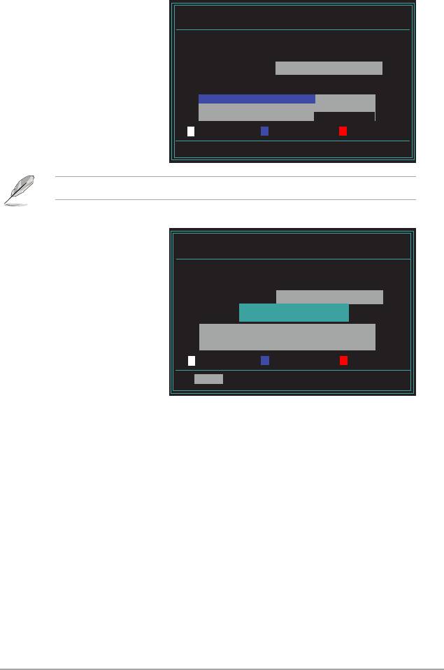
Updating the BIOS through the Internet
To update the BIOS through the Internet:
®
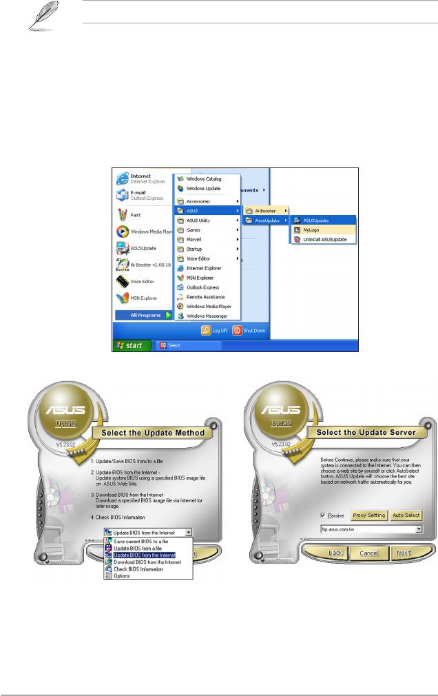
1. Launch the ASUS Update utility from the Windows
desktop by clicking Start
> Programs > ASUS > ASUSUpdate > ASUSUpdate. The ASUS Update
main window appears.
2. Select Update BIOS from the
3. Select the ASUS FTP site nearest
Internet option from the drop-down
you to avoid network trafc, or
menu, then click Next.
click Auto Select. Click Next.
4-2 Chapter 4: BIOS setup
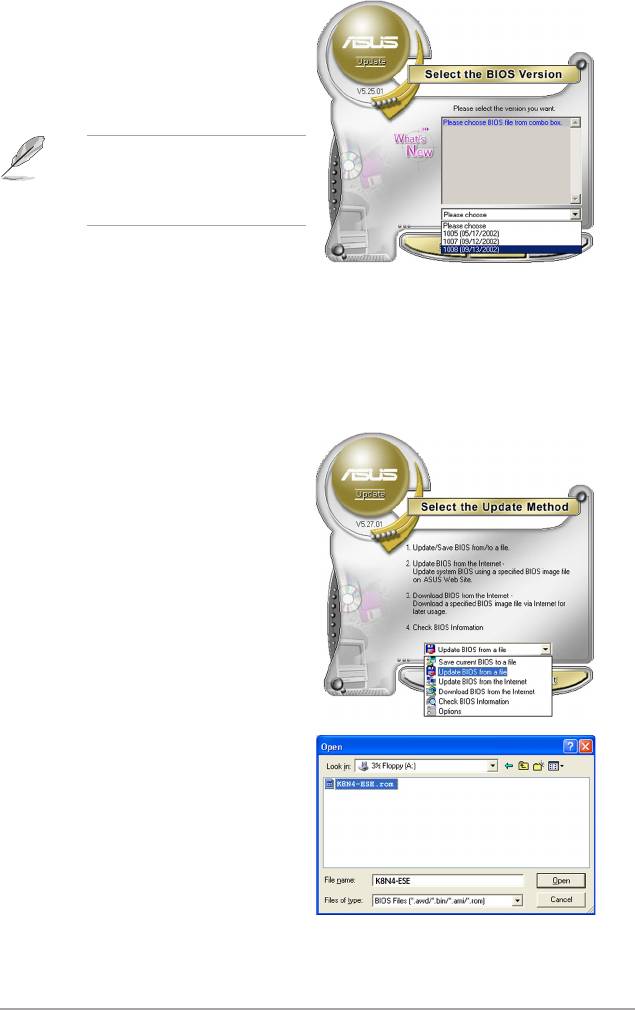
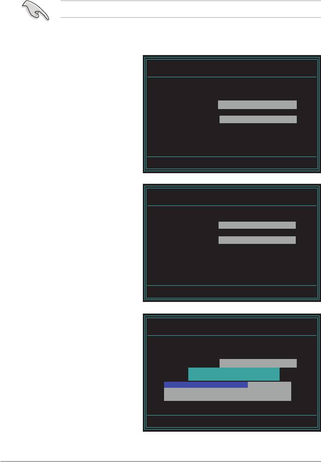
4. From the FTP site, select the BIOS
version that you wish to download.
Click Next.
5. Follow the screen instructions to
complete the update process.
The ASUS Update utility is
capable of updating itself through
the Internet. Always update the
utility to avail all its features.
Updating the BIOS through a BIOS le
To update the BIOS through a BIOS le:
®
1. Launch the ASUS Update utility from the Windows
desktop by clicking Start
> Programs > ASUS > ASUSUpdate > ASUSUpdate. The ASUS Update
main window appears.
2. Select Update BIOS from a le
option from the drop-down menu,
then click Next.
3. Locate the BIOS le from the Open
window, then click Open.
4. Follow the screen instructions to
complete the update process.
ASUS Crosshair 4-3

4.1.2 Creating a bootable oppy disk
1. Do either one of the following to create a bootable oppy disk.
DOS environment
a. Insert a 1.44MB oppy disk into the drive.
b. At the DOS prompt, type
format
A:/S then press <Enter>.
®
Windows
XP environment
a. Insert a 1.44 MB oppy disk to the oppy disk drive.
®
b. Click Start from the Windows
desktop, then select My Computer.
c. Select the 3 1/2 Floppy Drive icon.
d. Click File from the menu, then select Format. A Format 3 1/2 Floppy
Disk window appears.
e. Select Create an MS-DOS startup disk from the format options eld,
then click Start.
®
Windows
2000 environment
®
To create a set of boot disks for Windows
2000:
a. Insert a formatted, high density 1.44 MB oppy disk into the drive.
®
b. Insert the Windows
2000 CD to the optical drive.
c. Click Start, then select Run.
d. From the Open eld, type
D:\bootdisk\makeboot a:
assuming that D: is your optical drive.
e. Press <Enter>, then follow screen instructions to continue.
2. Copy the original or the latest motherboard BIOS le to the bootable oppy
disk.
4-4 Chapter 4: BIOS setup
4.1.3 ASUS EZ Flash 2 utility
The ASUS EZ Flash 2 feature allows you to update the BIOS without having to go
through the long process of booting from a oppy disk and using a DOS-based
utility. The EZ Flash utility is built-in the BIOS chip so it is accessible by pressing
<Alt> + <F2> during the Power-On Self Tests (POST).
To update the BIOS using EZ Flash 2:
1. Visit the ASUS website (www.asus.com) to download the latest BIOS le for
the motherboard.
2. Save the BIOS le to a oppy disk, then restart the system.
3. Press <Alt> + <F2> during POST to display the following.
Insert Disk then press Enter or ESC to continue POST
4. Insert the oppy disk that
AwardBIOS Flash Utility for ASUS V1.14
(C) Phoenix Technologies Ltd. All Rights Reserved
contains the BIOS le
to the oppy disk drive
For C51MCP55-CROSSHAIR-00 DATE:04/10/2006
Flash Type - Unknown Flash
then press <Enter>. The
following screen appears.
File Name to Program:
Message: Please wait...
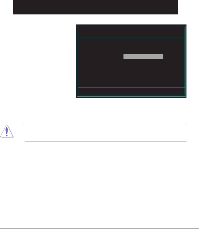
5. When the correct BIOS le is found, EZ Flash 2 performs the BIOS update
process and automatically reboots the system when done.
Do not shut down or reset the system while updating the BIOS to prevent
system boot failure!
ASUS Crosshair 4-5
4.1.4 Updating the BIOS
The Basic Input/Output System (BIOS) can be updated using the AwardBIOS
Flash Utility. Follow these instructions to update the BIOS using this utility.
1. Download the latest BIOS le from the ASUS web site. Unzip the le and
save it to a oppy disk.
Save only the updated BIOS le in the oppy disk to avoid loading the wrong
BIOS le.
2. Copy the AwardBIOS Flash Utility (awdash.exe) from the Software folder of
the support DVD to the oppy disk with the latest BIOS le.
3. Boot the system in DOS mode using the bootable oppy disk you created
earlier.
4. When the A:> appears, replace the bootable oppy disk with the oppy disk
containing the new BIOS le and the Award BIOS Flash Utility.
5. At the prompt, type
AwardBIOS Flash Utility for ASUS V1.14
awdash then press
(C) Phoenix Technologies Ltd. All Rights Reserved
<Enter>. The Award
For C51MCP55-CROSSHAIR-00 DATE:04/10/2006
BIOS Flash Utility screen
Flash Type - Unknown Flash
appears.
File Name to Program:
Message: Please input File Name!
6. Type the BIOS le name in
AwardBIOS Flash Utility for ASUS V1.14
the File Name to Program
(C) Phoenix Technologies Ltd. All Rights Reserved
eld, then press <Enter>.
For C51MCP55-CROSSHAIR-00 DATE:04/10/2006
Flash Type - Unknown Flash
File Name to Program: 0113.bin
Message: Do You Want To Save Bios (Y/N)
4-6 Chapter 4: BIOS setup
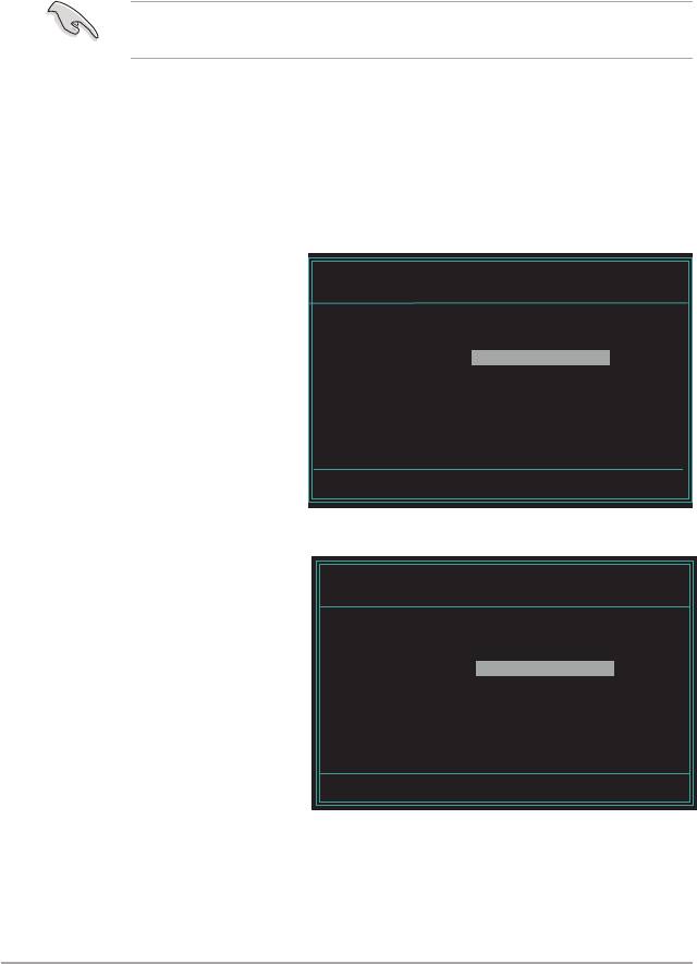
7. Press <N> when the utility prompts you to save the current BIOS le. The
following screen appears.
8. The utility veries the BIOS
AwardBIOS Flash Utility for ASUS V1.14
le in the oppy disk and
(C) Phoenix Technologies Ltd. All Rights Reserved
starts ashing the BIOS le.
For C51MCP55-CROSSHAIR-00 DATE:04/10/2006
Flash Type - Unknown Flash
File Name to Program: 0113.bin
Programming Flash Memory - OFE00 OK
Write OK No Update Write Fail
Warning: Don’t Turn Off Power Or Reset System!
Do not turn off or reset the system during the ashing process!
9. The utility displays a
AwardBIOS Flash Utility for ASUS V1.14
Flashing Complete
(C) Phoenix Technologies Ltd. All Rights Reserved
message indicating that
For C51MCP55-CROSSHAIR-00 DATE:04/10/2006
you have successfully
Flash Type - Unknown Flash
ashed the BIOS le.
File Name to Program: 0113.bin
Remove the oppy disk
Flashing Complete
Press <F1> to Continue
then press <F1> to restart
the system.
Write OK No Update Write Fail
F1
Reset
ASUS Crosshair 4-7
4.1.5 Saving the current BIOS le
You can use the AwardBIOS Flash Utility to save the current BIOS le. You can
load the current BIOS le when the BIOS le gets corrupted during the ashing
process.
Make sure that the oppy disk has enough disk space to save the le.
To save the current BIOS le using the AwardBIOS Flash Utility:
1. Follow steps 1 to 6 of the
AwardBIOS Flash Utility for ASUS V1.14
(C) Phoenix Technologies Ltd. All Rights Reserved
previous section.
For C51MCP55-CROSSHAIR-00 DATE:04/10/2006
2. Press <Y> when the utility
Flash Type - Unknown Flash
prompts you to save the
File Name to Program: 0113.bin
current BIOS le. The
following screen appears.
Save current BIOS as:
Message:
3. Type a lename for the
AwardBIOS Flash Utility for ASUS V1.14
(C) Phoenix Technologies Ltd. All Rights Reserved
current BIOS le in the
Save current BIOS as eld,
For C51MCP55-CROSSHAIR-00 DATE:04/10/2006
Flash Type - Unknown Flash
then press <Enter>.
File Name to Program: 0113.bin
Checksum: D800H
Save current BIOS as: old.bin
Message: Please Wait!
4. The utility saves the
AwardBIOS Flash Utility for ASUS V1.14
current BIOS le to the
(C) Phoenix Technologies Ltd. All Rights Reserved
oppy disk, then returns to
For C51MCP55-CROSSHAIR-00 DATE:04/10/2006
Flash Type - Unknown Flash
the BIOS ashing process.
File Name to Program: 0113.bin
Now Backup System BIOS to
File!
Message: Please Wait!
4-8 Chapter 4: BIOS setup

4.1.6 ASUS CrashFree BIOS 3 utility
The ASUS CrashFree BIOS 3 is an auto recovery tool that allows you to restore
the BIOS le when it fails or gets corrupted during the updating process. You can
update a corrupted BIOS le using the motherboard support DVD or the oppy disk
that contains the updated BIOS le.
Prepare the motherboard support DVD or the oppy disk containing the updated
motherboard BIOS before using this utility.
Recovering the BIOS from the support DVD
To recover the BIOS from the support DVD:
1. Turn on the system.
2. Insert the motherboard support DVD to the optical drive.
3. The utility displays the following message and automatically checks the DVD
for the BIOS le.
Award BootBlock BIOS v1.0
Copyright (c) 2000, Award Software, Inc.
BIOS ROM checksum error
Detecting IDE ATAPI device...
When found, the utility reads the BIOS le and starts ashing the corrupted
BIOS le.
Award BootBlock BIOS v1.0
Copyright (c) 2000, Award Software, Inc.
BIOS ROM checksum error
Detecting IDE ATAPI device...
Found CDROM, try to Boot from it... Pass
DO NOT shut down or reset the system while updating the BIOS! Doing so can
cause system boot failure!
4. Restart the system after the utility completes the updating process.
ASUS Crosshair 4-9

4.2 BIOS setup program
This motherboard supports a programmable Low-Pin Count (LPC) chip that you
can update using the provided utility described in section “4.1 Managing and
updating your BIOS.”
Use the BIOS Setup program when you are installing a motherboard, reconguring
your system, or prompted to“Run Setup.” This section explains how to congure
your system using this utility.
Even if you are not prompted to use the Setup program, you can change the
conguration of your computer in the future. For example, you can enable the
security password feature or change the power management settings. This
requires you to recongure your system using the BIOS Setup program so that the
computer can recognize these changes and record them in the CMOS RAM of the
LPC chip.
The LPC chip on the motherboard stores the Setup utility. When you start up the
computer, the system provides you with the opportunity to run this program. Press
<Del> during the Power-On Self-Test (POST) to enter the Setup utility; otherwise,
POST continues with its test routines.
If you wish to enter Setup after POST, restart the system by pressing
<Ctrl+Alt+Delete>, or by pressing the reset button on the system chassis. You can
also restart by turning the system off and then back on. Do this last option only if
the rst two failed.
The Setup program is designed to make it as easy to use as possible. Being a
menu-driven program, it lets you scroll through the various sub-menus and make
your selections from the available options using the navigation keys.
• The default BIOS settings for this motherboard apply for most conditions
to ensure optimum performance. If the system becomes unstable after
changing any BIOS settings, load the default settings to ensure system
compatibility and stability. Select the Load Default Settings item under the
Exit Menu. See section “4.9 Exit Menu.”
• The BIOS setup screens shown in this section are for reference purposes
only, and may not exactly match what you see on your screen.
• Visit the ASUS website (www.asus.com) to download the latest BIOS le for
this motherboard.
4-10 Chapter 4: BIOS setup

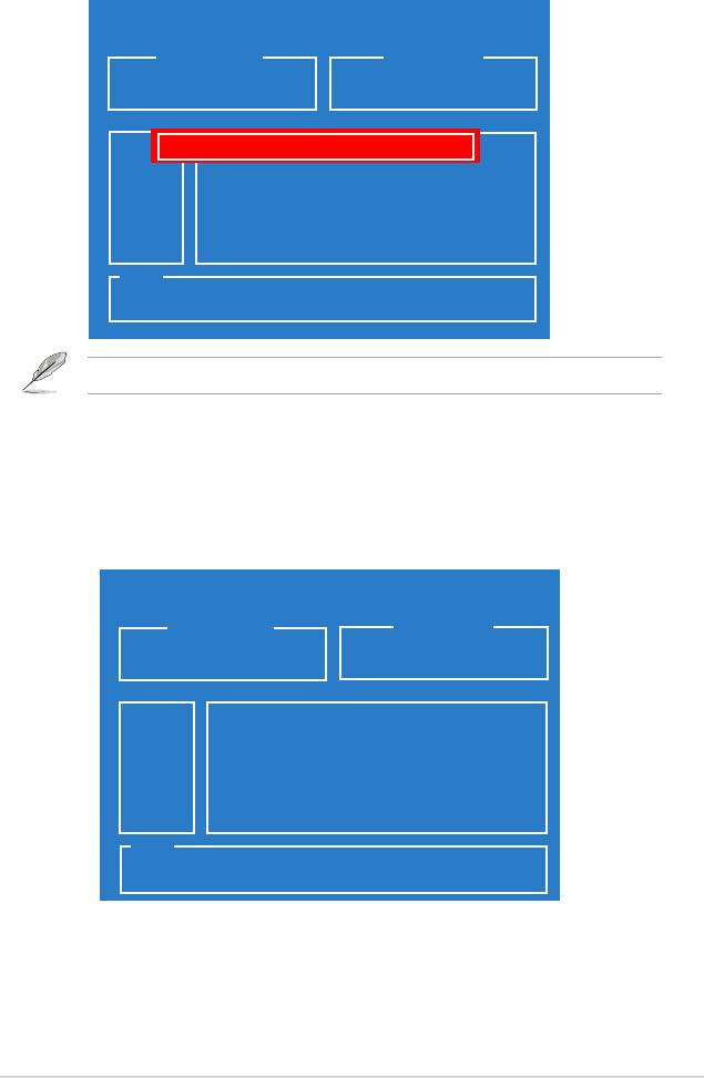
4.2.1 BIOS menu screen
Conguration eldsMenu items
General helpMenu bar
Phoenix-Award BIOS CMOS Setup Utility
Main Extreme Tweaker Advanced Power Boot Tools Exit
System Time 15 : 30 : 36
Select Menu
System Date Thu, Apr 6 2006
Language [English]
Item Specic Help
Legacy Diskette A: [1.44M, 3.5 in.]
Change the day, month,
year and century.
Primary IDE Master [ST321122A]
Primary IDE Slave [ASUS CDS520/A]
SATA1 [None]
SATA2 [None]SATA2 [None] [None]
SATA3 [None]SATA3 [None] [None]
SATA4 [None]SATA4 [None] [None]
SATA5 [None]SATA5 [None] [None]
SATA6 [None]SATA6 [None] [None]
HDD SMART Monitoring [Disabled]
Installed Memory 512MB
Usable Memory 511MB
F1:Help ↑↓ : Select Item -/+: Change Value F5: Setup Defaults
ESC: Exit →←: Select Menu Enter: Select SubMenu F10: Save and Exit
Sub-menu items
Legend bar
4.2.2 Menu bar
The menu bar on top of the screen has the following main items:
Main For changing the basic system conguration
Extreme Tweaker For changing the overclocking settings
Advanced For changing the advanced system settings
Power For changing the advanced power management (APM)
conguration
Boot For changing the system boot conguration
Tools For conguring options for special functions
Exit For selecting the exit options and loading default
settings
To select an item on the menu bar, press the right or left arrow key on the keyboard
until the desired item is highlighted.
• The BIOS setup screens shown in this chapter are for reference purposes
only, and may not exactly match what you see on your screen.
• Visit the ASUS website (www.asus.com) to download the latest BIOS
information.
ASUS Crosshair 4-11

4.2.3 Legend bar
At the bottom of the Setup screen is a legend bar. The keys in the legend bar allow
you to navigate through the various setup menus. The following table lists the keys
found in the legend bar with their corresponding functions.
Navigation Key Function
<F1> Displays the General Help screen
<F5> Loads setup default values
<Esc> Exits the BIOS setup or returns to the main menu from a
sub-menu
Left or Right arrow Selects the menu item to the left or right
Up or Down arrow Moves the highlight up or down between elds
Page Down or – (minus) Scrolls backward through the values for the highlighted eld
Page Up or + (plus) Scrolls forward through the values for the highlighted eld
<Enter> Brings up a selection menu for the highlighted eld
<F10> Saves changes and exit
4.2.4 Menu items
The highlighted item on the menu bar displays the specic items for that menu.
For example, selecting Main shows the Main menu items.
The other items (Advanced, Power, Boot, and Exit) on the menu bar have their
respective menu items.
4.2.5 Sub-menu items
A solid triangle before each item on any menu screen means that the item has a
sub-menu. To display the sub-menu, select the item and press <Enter>.
4.2.6 Conguration elds
These elds show the values for the menu items. If an item is user-congurable,
you can change the value of the eld opposite the item. You cannot select an item
that is not user-congurable.
A congurable eld is enclosed in brackets, and is highlighted when selected. To
change the value of a eld, select it then press <Enter> to display a list of options.
Refer to “4.2.7 Pop-up window.”
4-12 Chapter 4: BIOS setup

4.2.7 Pop-up window
Select a menu item then press <Enter> to display a pop-up window with the
conguration options for that item.
Phoenix-Award BIOS CMOS Setup Utility
Main Extreme Tweaker Advanced Power Boot Tools Exit
System Time 15 : 30 : 36
System Date Thu, Apr 6 2006
Language [English]
Select Menu
Legacy Diskette A: [1.44M, 3.5 in.]
Item Specic Help
Legacy Diskette A:
Primary IDE Master [ST321122A]
Species the capacity and
Primary IDE Slave [ASUS CDS520/A]
physical size of diskette
SATA1 [None]SATA1 [None] [None]
Disabled ..... [ ]
drive A.
SATA2 [None]SATA2 [None] [None]
720K , 3.5 in. ..... [ ]
SATA3 [None]SATA3 [None] [None]
1.44M, 3.5 in. ..... [ ]
SATA4 [None]SATA4 [None] [None]
SATA5 [None]SATA5 [None] [None]
SATA6 [None]SATA6 [None] [None]
HDD SMART Monitoring [Disabled]
Installed Memory 512MB
↑↓ :Move ENTER:Accept ESC:Abort
Usable Memory 512MB
F1:Help ↑↓ : Select Item -/+: Change Value F5: Setup Defaults
ESC: Exit →←: Select Menu Enter: Select SubMenu F10: Save and Exit
Pop-up menu
4.2.8 General help
At the top right corner of the menu screen is a brief description of the selected
item.
ASUS Crosshair 4-13
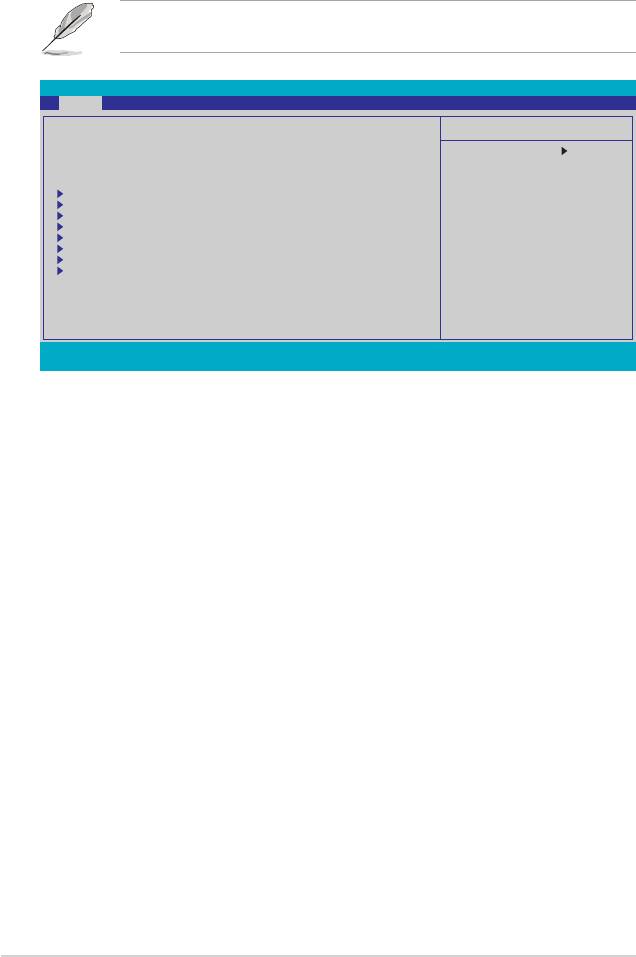
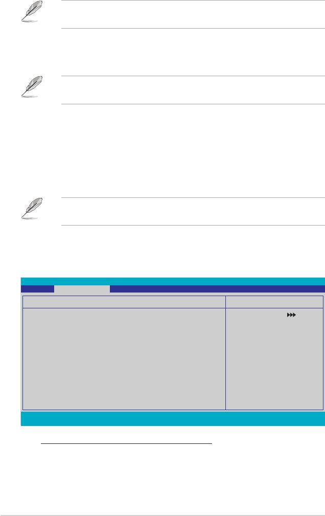
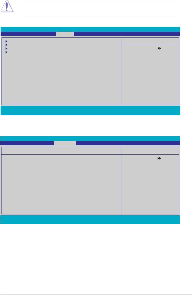
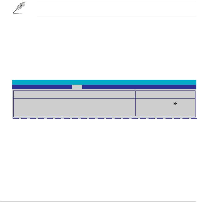
4.3 Main menu
When you enter the BIOS Setup program, the Main menu screen appears, giving
you an overview of the basic system information.
Refer to section “4.2.1 BIOS menu screen” for information on the menu screen
items and how to navigate through them.
Phoenix-Award BIOS CMOS Setup Utility
Main Extreme Tweaker Advanced Power Boot Tools Exit
System Time 15 : 30 : 36
Select Menu
System Date Thu, Apr 6 2006
Language [English]
Item Specic Help
Legacy Diskette A: [1.44M, 3.5 in.]
Change the day, month,
year and century.
Primary IDE Master [ST321122A]
Primary IDE Slave [ASUS CDS520/A]
SATA1 [None]SATA1 [None] [None]
SATA2 [None]SATA2 [None] [None]
SATA3 [None]SATA3 [None] [None]
SATA4 [None]SATA4 [None] [None]
SATA5 [None]SATA5 [None] [None]
SATA6 [None]SATA6 [None]6 [None]
HDD SMART Monitoring [Disabled]
Installed Memory 512MB
Usable Memory 511MB
F1:Help ↑↓ : Select Item -/+: Change Value F5: Setup Defaults
ESC: Exit →←: Select Menu Enter: Select SubMenu F10: Save and Exit
4.3.1 System Time [xx:xx:xx]
Allows you to set the system time.
4.3.2 System Date [Day xx/xx/xxxx]
Allows you to set the system date.
4.3.3 Language [English]
Allows you to choose the BIOS language version from the options. Conguration
options: [English] [French] [Deutsch] [Chines (Trad.)] [Chinese (Simp.)] [Japanese]
4.3.4 Legacy Diskette A [1.44M, 3.5 in.]
Sets the type of oppy drive installed.
Conguration options: [Disabled] [720K , 3.5 in.] [1.44M, 3.5 in.]
4-14 Chapter 4: BIOS setup

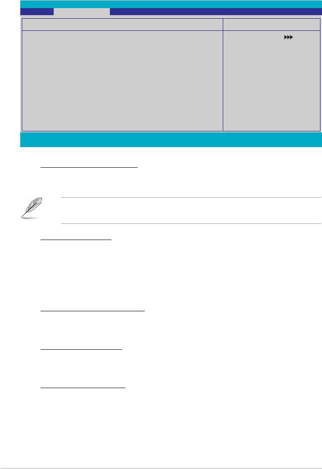
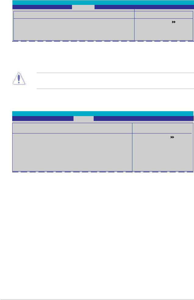
4.3.5 Primary IDE Master/Slave
While entering Setup, the BIOS automatically detects the presence of IDE devices.
There is a separate sub-menu for each IDE device. Select a device item then
press <Enter> to display the IDE device information.
Phoenix-Award BIOS CMOS Setup Utility
Main
Primary IDE Master
Select Menu
PIO Mode [Auto]
Item Specic Help
UDMA Mode [Auto]
Set a PIO mode for IDE
Primary IDE Master [Auto]
device. Mode0 through 4
Access Mode [Auto]
for successive increase in
performance.
Capacity 82 GB
Cylinder 39420
Head 16
Sector 255
Transfer Mode UDMA 5
F1:Help ↑↓ : Select Item -/+: Change Value F5: Setup Defaults
ESC: Exit →←: Select Menu Enter: Select SubMenu F10: Save and Exit
The BIOS automatically detects the values opposite the dimmed items
(Capacity, Cylinder, Head, Sector and Transfer Mode). These values are not
user-congurable. These items show N/A if no IDE device is installed in the
system.
PIO Mode [Auto]
Sets the PIO mode for the IDE device.
Conguration options: [Auto] [Mode 0] [Mode 1] [Mode 2] [Mode 3] [Mode 4]
UDMA Mode [Auto]
Disables or sets the UDMA mode. Conguration options: [Disable] [Auto]
Primary IDE Master/Slave [Auto]
Select [Auto] to automatically detect an IDE hard disk drive. If automatic detection
is successful, the BIOS automatically lls in the correct values for the remaining
elds on this sub-menu. If the hard disk was already formatted on a previous
system, the setup BIOS may detect incorrect parameters. Select [Manual] to
manually enter the IDE hard disk drive parameters. If no drive is installed select
[None]. Conguration options: [None] [Auto] [Manual]
ASUS Crosshair 4-15

Access Mode [Auto]
The default [Auto] allows automatic detection of an IDE hard disk drive.
Select [CHS] for this item if you set the IDE Primary Master/Slave to [Manual].
Conguration options: [CHS] [LBA] [Large] [Auto]
Before attempting to congure a hard disk drive, make sure you have the
correct conguration information supplied by the drive manufacturer. Incorrect
settings may cause the system to fail to recognize the installed hard disk.
Capacity
Displays the auto-detected hard disk capacity. This item is not congurable.
Cylinder
Shows the number of the hard disk cylinders. This item is not congurable.
Head
Shows the number of the hard disk read/write heads. This item is not congurable.
Sector
Shows the number of sectors per track. This item is not congurable.
Transfer Mode
Shows the Transfer mode. This item is not congurable.
After entering the IDE hard disk drive information into BIOS, use a disk utility,
such as FDISK, to partition and format new IDE hard disk drives. This is
necessary so that you can write or read data from the hard disk. Make sure to
set the partition of the Primary IDE hard disk drives to active.
4-16 Chapter 4: BIOS setup
4.3.6 SATA1/2/3/4/5/6
While entering Setup, the BIOS automatically detects the presence of Serial ATA
devices. There is a separate sub-menu for each SATA device. Select a device item
then press <Enter> to display the SATA device information.
Phoenix-Award BIOS CMOS Setup Utility
Main
SATA1
Select Menu
Extended IDE Drive [Auto]
Item Specic Help
Access Mode [Auto]
Selects the type of xed
Capacity 0 MB
disk connected to the
system.
Cylinder 0
Head 0
Landing Zone 0
Sector 0
F1:Help ↑↓ : Select Item -/+: Change Value F5: Setup Defaults
ESC: Exit →←: Select Menu Enter: Select SubMenu F10: Save and Exit
The BIOS automatically detects the values opposite the dimmed items (Capacity,
Cylinder, Head, Landing Zone and Sector). These values are not user-
congurable. These items show 0 if no SATA device is installed in the system.
Extended IDE Drive [Auto]
Selects the type of xed disk connected to the system.
Conguration options: [None] [Auto]
Access Mode [Auto]
Sets the sector addressing mode. Conguration options: [Large] [Auto]
Before attempting to congure a hard disk drive, make sure you have the
correct conguration information supplied by the drive manufacturer. Incorrect
settings may cause the system to fail to recognize the installed hard disk.
Capacity
Displays the auto-detected hard disk capacity. This item is not congurable.
Cylinder
Shows the number of the hard disk cylinders. This item is not congurable.
ASUS Crosshair 4-17

Head
Shows the number of the hard disk read/write heads. This item is not congurable.
Landing Zone
Shows the number of landing zone per track. This item is not congurable.
Sector
Shows the number of sectors per track. This item is not congurable.
After entering the IDE hard disk drive information into BIOS, use a disk utility,
such as FDISK, to partition and format new IDE hard disk drives. This is
necessary so that you can write or read data from the hard disk. Make sure to
set the partition of the Primary IDE hard disk drives to active.
4.3.7 HDD SMART Monitoring [Disabled]
Allows you to enable or disable the HDD Self-Monitoring Analysis and Reporting
Technology (SMART) feature. Conguration options: [Disabled] [Enabled]
4.3.8 Installed Memory [xxx MB]
Shows the size of installed memory.
4.3.9 Usable Memory [XXX MB]
Shows the size of usable memory.
4-18 Chapter 4: BIOS setup
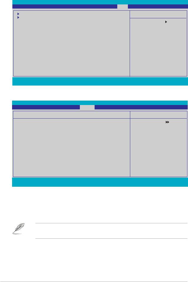
4.4 Extreme Tweaker menu
The Extreme menu items allow you to congure overclocking-related items.
Take caution when changing the settings of the Extreme menu items. Incorrect
eld values can cause the system to malfunction.
Phoenix-Award BIOS CMOS Setup Utility
Main Extreme Tweaker Advanced Power Boot Tools Exit
LinkBoost [Enabled]
Select Menu
AI Tuning [Auto]
x Overclock Options Disabled
Item Specic Help
x N.O.S Mode Auto
x N.O.S Sensitivity Normal
Press [Enter] to select
x N.O.S Overclock 3%
overclock prole.
x Overclocking
x Over Voltage
DRAM Conguration
SLI-Ready Memory [Disabled]
x SLI-Ready Memory CPUOC CPUOC 0%
AMD Live! [Disabled]
AMD Cool ‘n’ Quiet Function [Disabled]
NVIDIA GPU Ex [Disabled]
F1:Help ↑↓ : Select Item -/+: Change Value F5: Setup Defaults
ESC: Exit →←: Select Menu Enter: Select SubMenu F10: Save and Exit
4.4.1 LinkBoost [Enabled]
When you install 7900GTX or 7950 GX2 graphics card, this model will auto overclock to get a
better performance. Conguration options: [Disabled] [Enabled]
4.4.2 AI Tuning [Auto]
Allows selection of CPU overclocking options to achieve desired CPU internal
frequency. Selct either one of the preset overclocking conguration options:
Manual Allows you to individually set overclocking parameters.
Auto Loads the optimal settings for the system.
Standard Loads the standard settings for the system.
AI Overclock Loads overclocking proles with optimal parameters for
stability when overclocking.
AI N.O.S. The ASUS Non-delay Overclocking System feature
intelligently determines the system load and automatically
boosts the performance for the most demanding tasks.
The following item becomes user-congurable when you set AI Tuning to
[AI Overclock]
Overclock Options [Disabled]
Allows you to set the overclocking options.
Conguration options: [Disabled] [Overclock 3%] [Overclock 5%] [Overclock 8%]
[Overclock 10%]
ASUS Crosshair 4-19
The following item becomes user-congurable when you set AI Tuning to
[AI N.O.S.]
N.O.S. Mode [Auto]
Allows you to set the Non-delay Overclocking System mode.
Conguration options: [Auto] [Manual]
The following items become user-congurable when you set N.O.S. Mode to
[Manual].
N.O.S. Sensitivity [Normal]
Allows you to set the Non-delay Overclocking System sensitivity.
Conguration options: [Normal] [Sensitive] [Less-Sensitive]
N.O.S. Overclock [3%]
Allows you to set the Non-delay Overclocking System overclocking options.
Conguration options: [3%] [5%] [8%] [10%]
The Overclocking and Over Voltage items become user-congurable when
you set AI Tuning to [Manual].
Overclocking
This sub-menu allows you to adjust the system frequency-related items. Select an
item, then press <Enter> to edit.
Phoenix-Award BIOS CMOS Setup Utility
Extreme Tweaker
Overclocking
Select Menu
CPU Type AMD Athlon(tm) 64 Processor 3800+
Item Specic Help
CPU Speed 2000 MHz
Cache RAM 512K
CPU Frequency [Auto][Auto]
Memory Clock Frequency [Auto]
PCIEX16_1 Clock [Auto]
PCIEX16_2 Clock [Auto]
CPU<->NB HT Speed [Auto]
NB to SB HT Frequency [Auto][Auto]
NB --> SB HT Speed [5xNB to SB HT Frequency]
SB --> NB HT Speed [5xSB to NB HT Frequency]
CPU<->NB HT Width [↓16 ↑16]
NB<->SB HT Width [↓16 ↑16]
F1:Help ↑↓ : Select Item -/+: Change Value F5: Setup Defaults
ESC: Exit →←: Select Menu Enter: Select Sub-menu F10: Save and Exit
CPU Frequency [XXX] (value is auto-detected)
Indicates the frequency sent by the clock generator to the system bus and
PCI bus. The bus frequency (external frequency) multiplied by the bus
multiple equals the CPU speed. The BIOS auto-detects the value of this item.
The values range from 200.0 to 400.0.
4-20 Chapter 4: BIOS setup

Setting a very high CPU frequency may cause the system to become unstable.
If this happens, revert to the default setting.
CPU Multiplier [Auto]
Allows you to set the operating CPU multiplier. the conguration options may
vary depending on the type of CPU installed.
Conguration options:[Auto] [5x] [6x]~[25x]
Memory Clock Frequency [Auto]
Sets the memory clock frequency.
Conguration options: [Auto] [DDR2 400] [DDR2 533] [DDR2 667] [DDR2
800]
PCIEX16_1 / PCIEX16_2 Clock [Auto]PCIEX16_2 Clock [Auto]Clock [Auto]
Allows you to set the PCI Express clock.
Conguration options: [Auto] [100MHz] ~[200MHz]
CPU<->NB HT Speed [Auto]
Allows you to set the CPU to Northbridge HT Speed.
Conguration options: [Auto] [1xCPU Frequency] [2xCPU Frequency]
[3xCPU Frequency] [4xCPU Frequency] [5xCPU Frequency]
NB to SB HT Frequency [Auto]
Allows you to set the Northbridge to Southbridge HT frequency.
Conguration options: [Auto] [200MHz] ~ [400MHz]
NB-->SB HT Speed [5xNB to SB HT Frequency]
Allows you to set the Northbridge to Southbridge HT Speed.
Conguration options: [1xNB to SB HT Frequency] [2xNB to SB HT
Frequency] [3xNB to SB HT Frequency] [4xNB to SB HT Frequency] [5xNB
to SB HT Frequency]
SB-->NB HT Speed [5xSB to NB HT Frequency]
Allows you to set the Southbridge to Northbridge HT Speed.
Conguration options: [1xSB to NB HT Frequency] [2xSB to NB HT
Frequency] [3xSB to NB HT Frequency] [4xSB to NB HT Frequency] [5xSB to
NB HT Frequency]
CPU<->NB HT Width [↓16 ↑16]
Allows you to set the CPU to Northbridge HT width.
Conguration options: [↓8 ↑8] [↓16 ↑16]
NB<->SB HT Width [↓16 ↑16]
Allows you to set the Northbridge to Southbridge HT width.
Conguration options: [↓4 ↑4] [↓8 ↑8] [↓16 ↑16]
ASUS Crosshair 4-21
Over Voltage
This sub-menu allows you to adjust the voltage-related items. Select an item, then
press <Enter> to edit.
Phoenix-Award BIOS CMOS Setup Utility
Extreme Tweaker
Advanced Voltage Control
Select Menu
CPU Voltage Range [Auto]
Item Specic Help
x CPU Voltage Auto
DDR2 Voltage Control [Auto]
Press [Enter] to set.
HT Link Voltage [Auto]
NB Core Voltage [Auto]
SB Core Voltage [Auto]
SB PLL Voltage [Auto]
DDR2 Termination Voltage [Auto]
DDR2 Controller Ref Voltage [Auto]
DDR2 Channel A Ref Voltage [Auto]
DDR2 Channel B Ref Voltage [Auto]
F1:Help ↑↓ : Select Item -/+: Change Value F5: Setup Defaults
ESC: Exit →←: Select Menu Enter: Select Sub-menu F10: Save and Exit
CPU Voltage Range [Auto]
Allows you to set the operating CPU voltage range.
Conguration options: [Auto] [0.85V-0.95V] [0.95V-1.05V] ~ [1.75V-1.85V]
The following item becomes user-congurable when you set the CPU Voltage
Range to any of the available options, except [Auto].
CPU Voltage [Auto]
Allows you to set the operating CPU voltage.
Conguration options: [Auto] [1.75000V] [1.75625V] [1.76250V] [1.76875V]
[1.77500V] [1.78125V] [1.78750V] [1.79375V] [1.8000V] [1.80625V]
[1.81250V] [1.81875V] [1.82500V] [1.83125V] [1.83750V] [1.84375V]
[1.85000V]
DDR2 Voltage Control [Auto]
Allows you to set the operating DDR2 voltage.
Conguration options: [Auto] [1.850V] [1.875V] [1.900V] ~ [3.425V]
HT Link Voltage [Auto]
Allows you to set the HT Link voltage.
Conguration options: [Auto] [1.200V] [1.225V] [1.250V] [1.275V] ~ [1.575V]
NB Core Voltage [Auto]
Allows you to set the NB Core voltage.
Conguration options: [Auto] [1.200V] [1.225V] [1.250V] [1.275V]~[1.575V]
4-22 Chapter 4: BIOS setup
SB Core Voltage [Auto]
Allows you to set the SB Core voltage.
Conguration options: [Auto] [1.500V] [1.525V] [1.550V]~[1.875V]
SB PLL Voltage [Auto]
Allows you to set the SB PLL voltage.
Conguration options: [Auto] [1.50V] [1.55V]~[1.85V]
DDR2 Termination Voltage [Auto]
Allows you to set the DDR2 termination voltage.
Conguration options: [Auto] [DDR2_Vol/2] [DDR2_Vol/2 -50mV]
[DDR2_Vol/2-100mV] [DDR2_Vol/2-150mV] [DDR2_Vol/2+ 50mV]
[DDR2_Vol/2+100mV] [DDR2_Vol/2+150mV]
DDR2 Controller Ref Voltage [Auto]
Allows you to set the DDR2 Controller Ref Voltage
Conguration options: [Auto] [DDR2_Vol/2] [DDR2_Vol/2- 50mV]
[DDR2_Vol/2-100mV] [DDR2_Vol/2-150mV] [DDR2_Vol/2+ 50mV]
[DDR2_Vol/2+100mV] [DDR2_Vol/2+150mV]
DDR2 Channel A Ref Voltage / DDR2 Channel B Ref Voltage [Auto]
Allows you to set the DDR2 Controller/ChannelA/B Ref voltage.
Conguration options: [Auto] [DDR2_Vol/2] [DDR2_Vol/2-100mV] [DDR2_
Vol/2+ 50mV] [DDR2_Vol/2+100mV] [DDR2_Vol/2+150mV]
4.4.3 DRAM Conguration
The items in the sub-menu show the DRAM-related information auto-detected by
the BIOS.
Phoenix-Award BIOS CMOS Setup Utility
Extreme Tweaker
DRAM Conguration
Select Menu
Tcl [Auto]
Item Specic Help
Trcd [Auto]
Trp [Auto]
Press [Enter] to set.
Tras [Auto]
Width of DRAM Interface [Auto]
1T/2T Memory Timing [Auto]
AI Clock Skew [Auto]
x Channel A Clock Skew Normal
X Channel B Clock Skew Normal
Advanced Memory Settings
DRAM Timing Control
Output Driver Control
Current DRAM Timing 533MHz-4-4-4-11-1T
F1:Help ↑↓ : Select Item -/+: Change Value F5: Setup Defaults
ESC: Exit →←: Select Menu Enter: Select Sub-menu F10: Save and Exit
ASUS Crosshair 4-23

Tcl [Auto]
Conguration options: [Auto] [3] [4] [5] [6]
Trcd [Auto]
Conguration options: [Auto] [3] [4] [5] [6]
Trp [Auto]
Conguration options: [Auto] [3] [4] [5] [6]
Tras [Auto]
Conguration options: [Auto] [5] [6] [7]~[18]
Width of DRAM Interface [Auto]
Conguration options: [Auto] [64-bit]
1T/2T Memory Timing [Auto]
Conguration options: [Auto] [1T] [2T]
DRAM ECC Enable [Disabled]
Enables or disables the DRAM ECC function.
Conguration options: [Disabled] [Enabled]
This item appears only when you install DRAM modules that support ECC
function.
AI Clock Skew [Auto]
Below items become user-congurable when you set the AI Clock Skew to
[Manual].
Channel A Clock Skew: [Advance 900ps] [Advance 750ps] [Advance 600ps]
[Advance 450ps] [Advance 300ps] [Advance 150ps] [Normal] [Delay 150ps]
[Delay 300ps] [Delay 450ps] [Delay 600ps] [Delay 750ps] [Delay 900ps]
Channel B Clock Skew: [Advance 900ps] [Advance 750ps] [Advance 600ps]
[Advance 450ps] [Advance 300ps] [Advance 150ps] [Normal] [Delay 150ps]
[Delay 300ps] [Delay 450ps] [Delay 600ps] [Delay 750ps] [Delay 900ps]
4-24 Chapter 4: BIOS setup

Advanced Memory Settings
Phoenix-Award BIOS CMOS Setup Utility
Extreme Tweaker
Advanced Memory Settings
Select Menu
CPU On-die Termination [Auto]
Item Specic Help
Trc [Auto]
Twr [Auto]
Press [Enter] to set.
Trrd [Auto]
Trwt [Auto]
Twtr [Auto]
Trtp [Auto]
Twrrd [Auto]
Twrwr [Auto]
Trdrd [Auto]
Tref [Auto]
Trfc [Auto]
DRAM Termination [Auto]
Max Async Latency [Auto][Auto]
R/W Queue Bypass [Auto]
Dynamic Idle Cycle Counter [Auto]
Idle Cycle Limit [Auto]
DCQ Bypass Maximum [Auto]
DRAM Burst Length [Auto]
DRAM Bank Interleaving [Enabled]
F1:Help ↑↓ : Select Item -/+: Change Value F5: Setup Defaults
ESC: Exit →←: Select Menu Enter: Select Sub-menu F10: Save and Exit
CPU On-die Termination [Auto]
Conguration options: [Auto] [300 ohm] [150 ohm] [75 ohm]
Trc [Auto]
Conguration options: [Auto] [11] [12] [13]~[26]
Twr [Auto]
Conguration options: [Auto] [3] [4] [5] [6]
Trrd [Auto]
Conguration options: [Auto] [2] [3] [4] [5]
Trwt [Auto]
Conguration options: [Auto] [2] [3] [4] [5] ~ [9]
Twtr [Auto]
Conguration options: [Auto] [1] [2] [3]
Trtp [Auto]
Conguration options: [Auto] [2/4] [3/5]
Twrrd [Auto]
Conguration options: [Auto] [0] [1] [2] [3]
Twrwr [Auto]
Conguration options: [Auto] [1] [2] [3]
Trdrd [Auto]
Conguration options: [Auto] [2] [3] [4] [5]
Tref [Auto]
Conguration options: [Auto] [7.8 us] [3.9 us]
Trfc [Auto]
Conguration options: [Auto] [0] [1] [2] [3]
DRAM Termination [Auto]
Conguration options: [Auto] [Disabled] [75 ohms] [150 ohms] [50 ohms]
Max Async Latency [Auto]
Conguration options: [Auto] [0 ns] [1 ns] [2 ns] ~ [15 ns]
ASUS Crosshair 4-25

R/W Queue Bypass [Auto]
Conguration options: [Auto] [2x] [4x] [8x] [16x]
Dynamic Idle Cycle Counter [Auto]
Conguration options: [Auto] [Disabled] [Enabled]
Idle Cycle Limit [Auto]
Conguration options: [Auto] [0 cycles] [4 cycles] [8 cycles] [16 cycles] [32 cycles]
[64 cycles] [128 cycles] [256 cycles]
DCQ Bypass Maximum [Auto]
Conguration options: [Auto] [0x] [1x] [2x]~[15x]
DRAM Burst Length [Auto]
Conguration options: [Auto] [64-byte] [32-byte]
DRAM Bank Interleaving [Enabled]
Conguration options: [Disabled] [Enabled]
DRAM Timing Control
Phoenix-Award BIOS CMOS Setup Utility
Extreme Tweaker
DRAM Timing Control
Select Menu
CHA CKE Fine Delay [Auto]
Item Specic Help
CHB CKE Fine Delay [Auto]
CHA CKE Setup Time [Auto]
Press [Enter] to set.
CHB CKE Setup Time [Auto]
CHA CS/ODT Fine Delay [Auto]
CHB CS/ODT Fine Delay [Auto]
CHA CS/ODT Setup Time [Auto]
CHB CS/ODT Setup Time [Auto]
CHA Add/CMD Fine Delay [Auto]
CHB Add/CMD Fine Delay [Auto]
CHA Add/CMD Setup Time [Auto]
CHB Add/CMD Setup Time [Auto]
Read DQS Timing Control [Auto]
Write Data Timing Control [Auto]
DQS Receiver Enable Timing [Auto]
F1:Help ↑↓ : Select Item -/+: Change Value F5: Setup Defaults
ESC: Exit →←: Select Menu Enter: Select Sub-menu F10: Save and Exit
CHA/CHB CKE Fine Delay [Auto]
Conguration options: [Auto] [No delay] [1/64 MEMCLK delay] [2/64 MEMCLK delay]
[3/64 MEMCLK delay] ~ [31/64 MEMCLK delay]
CHA/CHB CKE Setup Time [Auto]
Conguration options: [Auto] [1/2 MEMCLK] [1 MEMCLK]
CHA/CHB C/S ODT Fine Delay [Auto]
Conguration options: [Auto] [No delay] [1/64 MEMCLK delay] [2/64 MEMCLK delay]
[3/64 MEMCLK delay] ~ [31/64 MEMCLK delay]
CHA/CHB C/S ODT Setup Time [Auto]
Conguration options: [Auto] [1/2 MEMCLK] [1 MEMCLK]
CHA/CHB Add/CMD Fine Delay [Auto]
Conguration options: [Auto] [No delay] [1/64 MEMCLK delay] [2/64 MEMCLK delay]
[3/64 MEMCLK delay] ~ [31/64 MEMCLK delay]
CHA/CHB Add/CMD Setup Time [Auto]
Conguration options: [Auto] [1/2 MEMCLK] [1 MEMCLK]
Read DQS Timing Control [Auto]
Conguration options: [Auto] [No delay] [1/96 MEMCLK delay] [2/96 MEMCLK delay]
[3/96 MEMCLK delay] ~ [47/96 MEMCLK delay]
4-26 Chapter 4: BIOS setup

Write Data Timing Control [Auto]
Conguration options: [Auto] [No delay] [1/96 MEMCLK delay] [2/96 MEMCLK delay]
[3/96 MEMCLK]...[47/96 MEMCLK delay]
DQS Receiver Enable Timing [Auto]
Conguration options: [Auto] [0 ps] [50 ps] [100 ps] [150 ps] ~ [8700 ps]
Output Driver Control
Phoenix-Award BIOS CMOS Setup Utility
Extreme Tweaker
Output Driver Control
Select Menu
CHA CKE Drive Strength [Auto]
Item Specic Help
CHB CKE Drive Strength [Auto]
CHA CS/ODT Drive Strength [Auto]
Press [Enter] to set.
CHB CS/ODT Drive Strength [Auto]
CHA Add/CMD Drive Strength [Auto]Add/CMD Drive Strength [Auto]
CHB Add/CMD Drive Strength [Auto]Add/CMD Drive Strength [Auto]
MEMCLK Drive Strength [Auto]MEMCLK Drive Strength [Auto]
Data Drive Strength [Auto]
DQS Drive Strength [Auto]
DRAM Drivers Weak Mode [Auto]
F1:Help
↑↓
: Select Item -/+: Change Value F5: Setup Defaults
ESC: Exit
→←
: Select Menu Enter: Select Sub-menu F10: Save and Exit
CHA/CHB CKE Drive Strength [Auto]
Conguration options: [Auto] [1.00x] [1.25x] [1.50x] [2.00x]
CHA/CHB C/S ODT Drive Strength [Auto]
Conguration options: [Auto] [1.00x] [1.25x] [1.50x] [2.00x]
CHA/CHB Add/CMD Drive Strength [Auto]
Conguration options: [Auto] [1.00x] [1.25x] [1.50x] [2.00x]
MEMCLK Drive Strength [Auto]
Conguration options: [Auto] [0.75x] [1.00x] [1.25x] [1.50x]
Data Drive Strength [Auto]
Conguration options: [Auto] [0.75x] [1.00x] [1.25x] [1.50x]
DQS Drive Strength [Auto]
Conguration options: [Auto] [0.75x] [1.00x] [1.25x] [1.50x]
DRAM Drivers Weak Mode [Auto]
Conguration options: [Auto] [Normal] [Weak]
ASUS Crosshair 4-27

4.4.4 SLI-Ready Memory [Disabled]
Allows you to select the SPD prole for SLI-Ready memory modules. The
conguration options may vary depending on the type of module you installed.
Conguration options: [Disabled] [Optimal] [High Performance] [High Frequency]
The following item becomes user-congurable when SLI-Ready Memory is set
to Enabled.
4.4.5 SLI-Ready Memory CPUOC [CPUOC 0%]
Conguration options: [CPUOC 0%] [CPUOC 1%]~[CPUOC 14%] [CPUOC MAX]
4.4.6 AMD Live! [Disabled]
Enables or disables AMD Live!
Conguration options: [Disabled] [Enabled]
4.4.7 AMD Cool ‘n’ Quiet Function [Disabled]
Enables or disables the AMD Cool ‘n’ Quiet technology.
Conguration options: [Auto] [Disabled]
4.4.8 NVIDIA GPU Ex [Disabled]
Enables or disables with the optimized NVIDIA Ex graphics driver.
Conguration options: [Auto] [Disabled]
4-28 Chapter 4: BIOS setup
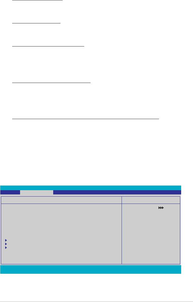
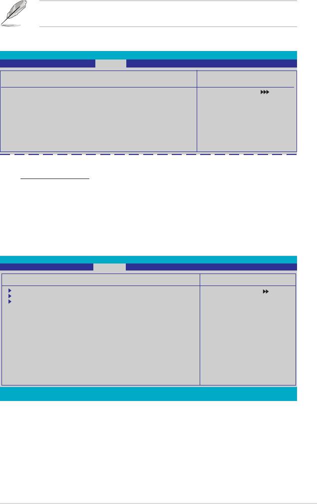
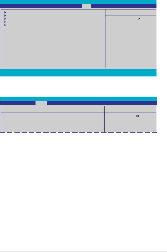
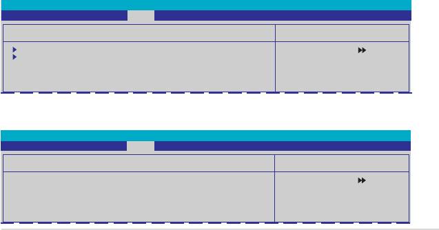
4.5 Advanced menu
The Advanced menu items allow you to change the settings for system devices.
Take caution when changing the settings of the Advanced menu items. Incorrect
eld values can cause the system to malfunction.
Phoenix-Award BIOS CMOS Setup Utility
Main Extreme Tweaker Advanced Power Boot Tools Exit
AI NET2
Select Menu
PEG Link Mode
PCIPnP
Item Specic Help
Onboard Device Conguration
Press [Enter] to set.
F1:Help ↑↓ : Select Item -/+: Change Value F5: Setup Defaults
ESC: Exit →←: Select Menu Enter: Select SubMenu F10: Save and Exit
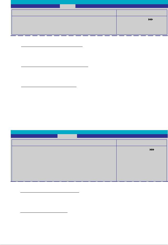
4.5.1 AI NET2
Phoenix-Award BIOS CMOS Setup Utility
Advanced
AI NET2
Select Menu
POST Check LAN Cable [Disabled]
Item Specic Help
POST Check LAN2 Cable [Disabled]
Enable or Disable LAN
Pair Status Length
cable check during POST.
LAN1(1-2) Open N/A
LAN1(3-6) Open N/A
LAN1(4-5) Open N/A
LAN1(7-8) Open N/A
LAN2(1-2) Open N/A
LAN2(3-6) Open N/A
LAN2(4-5) Open N/A
LAN2(7-8) Open N/A
F1:Help ↑↓ : Select Item -/+: Change Value F5: Setup Defaults
ESC: Exit →←: Select Menu Enter: Select Sub-menu F10: Save and Exit
POST Check LAN Cable [Disabled]
POST Check LAN2 Cable [Disabled]
Enables or disables checking of the LAN/LAN2 cable during the Power-On
Self-Test (POST). Conguration options: [Disabled] [Enabled]
ASUS Crosshair 4-29
4.5.2 PEG Link Mode
Phoenix-Award BIOS CMOS Setup Utility
Advanced
PEG Link Mode
Select Menu
PEG Link Mode [Auto]
Item Specic Help
Enhance performance on
PCIE serial graphic card.
PEG Link Mode [Auto]
Allows you to enhance the performance of your PCI Express graphics card.
Conguration options: [Auto] [Disabled] [Normal] [Fast] [Faster]
Setting to [Fast] or [Faster] may cause your system to be unstable. If this
happens, revert to the default setting [Auto].
4.5.3 PCIPnP
Phoenix-Award BIOS CMOS Setup Utility
Advanced
PCIPnP
Select Menu
Plug & Play O/S [No]
Item Specic Help
Resources Controlled By [Auto]
Select Yes if you are using
x IRQ Resources
a Plug and Play capable
operating system. Select
No if you need the BIOS to
congure non-boot devices.
Plug & Play O/S [No]
When set to [No], the BIOS congures all the devices in the system. When set to
[Yes] and if you install a Plug and Play operating system, the operating system
congures the Plug and Play devices not required for boot. Conguration options:
[No] [Yes]
Resources Controlled By [Auto]
When set to [Auto], the BIOS automatically congures all the boot and Plug and
Play compatible devices. Set to [Manual] if you want to assign the IRQ DMA and
memory base address elds. Conguration options: [Auto] [Manual]
4-30 Chapter 4: BIOS setup
The item IRQ Resources becomes user-congurable when you set Resources
Controlled By to [Manual].
IRQ Resources
Phoenix-Award BIOS CMOS Setup Utility
Advanced
IRQ Resources
Select Menu
IRQ-5 assigned to [PCI Device]
Item Specic Help
IRQ-7 assigned to [PCI Device]
IRQ-9 assigned to [PCI Device]
Legacy ISA for devices
IRQ-10 assigned to [PCI Device]
compliant with the original
IRQ-11 assigned to [PCI Device]
PC AT bus specication,
IRQ-14 assigned to [PCI Device]
PCI/ISA PnP for devices
IRQ-15 assigned to [PCI Device]
compliant with the Plug
and Play standard whether
designed for PCI or ISA
bus architecture.
IRQ-xx assigned to
When set to [PCI Device], the specic IRQ is free for use of PCI/PnP
devices. When set to [Reserved], the IRQ is reserved for legacy ISA devices.
Conguration options: [PCI Device] [Reserved]
4.5.4 Onboard Device Conguration
Phoenix-Award BIOS CMOS Setup Utility
Advanced
Onboard Device Conguration
Select Menu
IDE Function Setup
Item Specic Help
Serial-ATA Conguration
USB Conguration
Onboard 1394 Controller [Enabled]
Onboard 1st nVidia LAN [Enabled]
Onboard 2nd nVidia LAN [Enabled]
Onboard nVidia Lan Boot ROM [Disabled]
Primary Display Adapter [PCIEX16_1]
HD Audio [Auto]
Front Panel Support Type [AC97][AC97]
Silicon SATAII Controller [SATA Mode]
Internal Connector LED [Disabled]
LCD Poster Back Light [Disabled]
LCD Poster Mode [Current Time]
x LCD Poster String
F1:Help ↑↓ : Select Item -/+: Change Value F5: Setup Defaults
ESC: Exit →←: Select Menu Enter: Select SubMenu F10: Save and Exit
ASUS Crosshair 4-31
IDE Function Setup
This sub-menu contains IDE function-related items. Select an item then press
<Enter> to edit.
Phoenix-Award BIOS CMOS Setup Utility
Advanced
IDE Function Setup
Select Menu
OnChip IDE Channel0 [Enabled]
Item Specic Help
IDE DMA transfer access [Enabled]
IDE Prefetch Mode [Enabled]
OnChip IDE Channel0 [Enabled]
Allows you to enable or disable the onchip IDE channel 0 controller .
Conguration options: [Disabled] [Enabled]
IDE DMA transfer access [Enabled]
Allows you to enable or disable the IDE DMA transfer access.
Conguration options: [Disabled] [Enabled]
IDE Prefetch Mode [Enabled]
Allows you to enable or disable the IDE PIO read prefetch mode.
Conguration options: [Disabled] [Enabled]
Serial-ATA Conguration
This sub-menu allows you to change Serial ATA settings. Select an item then press
<Enter> to edit.
Phoenix-Award BIOS CMOS Setup Utility
Advanced
Serial-ATA Conguration
Select Menu
Serial-ATA Controller [Enabled]
Item Specic Help
RAID Enabled [Disabled]
x SATA1 RAID Disabled
x SATA2 RAID Disabled
x SATA3 RAID Disabled
x SATA4 RAID Disabled
x SATA5 RAID Disabled
x SATA6 RAID Disabled
Serial-ATA Controller [Enabled]
Allows you to enable or disable the onboard Serial ATA controller.
Conguration options: [Disabled] [Enabled]
RAID Enabled [Disabled]
Enables or disables the onboard RAID controller. When set to [Enabled],
the succeeding items become user-congurable. Conguration options:
[Disabled] [Enabled]
4-32 Chapter 4: BIOS setup

SATA1/2/3/4/5/6 [Disabled]
Enables or disables the RAID function of the rst to sixth SATA master drive.
Conguration options: [Disabled] [Enabled]
USB Conguration
The items in this menu allows you to change the USB-related features. Select an
item then press <Enter> to display the conguration options.
Phoenix-Award BIOS CMOS Setup Utility
Advanced
USB Conguration
Select Menu
USB Controller [Enabled]
Item Specic Help
USB2.0 Controller [Enabled]
USB Legacy support [Enabled]
Enable or disable
the USB 1.1 and 2.0
Controller.
USB Controller [Enabled]
Allows you to enable or disable the onchip USB controller.
Conguration options: [Disabled] [Enabled]
USB 2.0 Controller [Enabled]
Allows you to enable or disable the USB 2.0 controller.
Conguration options: [Disabled] [Enabled]
USB Legacy Support [Enabled]
Allows you to enable or disable support for USB devices on legacy operating
systems (OS). Conguration options: [Disabled] [Enabled]
Onboard 1394 [Enabled]
Allows you to disable or enable the onboard 1394 device support.
Conguration options: [Disabled] [Enabled]
Onboard 1st/2nd Nvidia LAN [Enabled]
®
Enables or disables the onboard NVIDIA
LAN controller.
Conguration options: [Disabled] [Enabled]
OnBoard nVidia LAN Boot ROM [Disabled]
Allows you to enable or disable the onboard LAN boot ROM.
Conguration options: [Enabled] [Disabled]
Primary Display Adapter [PCIEX16_1]
Allows you to select the graphics controller to use as the primary boot device.
Conguration options: [PCI Slot] [PCIEX16_2] [PCIEX16_1]
ASUS Crosshair 4-33

HD Audio [Auto]
Allows you to disable or set the High-Denition audio function.
Conguration options: [Auto] [Disabled]
Front Panel Support Type [AC97]
Allows you to set the front panel audio connector (AAFP) mode to legacy AC`97
or high-denition audio depending on the audio standard that the front panel audio
module supports. Conguration options: [AC97] [HD Audio]
Silicon SATAII Controller [SATA Mode]
Allows you to disable or set the function of the extended SATA II controller.
Conguration options: [Disabled] [SATA Mode] [RAID Mode]
Internal Connector LED [by Switch]
Allows you to control the internal connector LED by Switch or Always on.
Conguration options: [By Switch] [Always On]
LCD Poster Back Light [Disabled]
Allows you to enable or disable the LCD poster backlight.
Conguration options: [Disabled] [Enabled]
LCD Poster Mode [Current Time]
Allows you to select the LCD poster mode.
Conguration options: [Current Time] [User String]
The following item becomes congurable when the “LCD Poster Mode” item is
set to [User String].
LCD Poster String
Allows you to enter a string on the LCD poster.
4-34 Chapter 4: BIOS setup

4.6 Power menu
The Power menu items allow you to change the settings for the Advanced
Conguration and Power Interface (ACPI) and the Advanced Power Management
(APM). Select an item then press <Enter> to display the conguration options.
Phoenix-Award BIOS CMOS Setup Utility
Main Extreme Tweaker Advanced Power Boot Tools Exit
ACPI Suspend Type [S1&S3]
Select Menu
ACPI APIC support [Enabled]
APM Conguration
Item Specic Help
Hardware Monitor
Press [Enter] to select
overclock prole.
F1:Help ↑↓ : Select Item -/+: Change Value F5: Setup Defaults
ESC: Exit →←: Select Menu Enter: Select SubMenu F10: Save and Exit
4.6.1 ACPI Suspend Type [S1&S3]
Allows you to select the Advanced Conguration and Power Interface (ACPI)
state to be used for system suspend. Conguration options: [S1 (POS)] [S3(STR)]
[S1&S3]
4.6.2 ACPI APIC Support [Enabled]
Allows you to enable or disable the Advanced Conguration and Power Interface
(ACPI) support in the Application-Specic Integrated Circuit (ASIC). When set
to Enabled, the ACPI APIC table pointer is included in the RSDT pointer list.
Conguration options: [Disabled] [Enabled]
ASUS Crosshair 4-35

4.6.3 APM Conguration
Phoenix-Award BIOS CMOS Setup Utility
Power
APM Conguration
Select Menu
Restore on AC Power Loss [Power-Off]
Item Specic Help
PWR Button < 4 secs [Instant-Off]
Power Up On PCI/PCIE Devices [Disabled]
Press [Enter] to select
USB Resume from S5 [Disabled]
Power On by RTC Alarm [Disabled]
whether or not to restart
x Date (of Month) Alarm [ 0]
the system after AC power
x Alarm Time (hh:mm) 0 : 0 : 0
loss.
Power Up By PS/2 Mouse [Disabled]
Power Up By PS/2 Keyboard [Disabled]
F1:Help ↑↓ : Select Item -/+: Change Value F5: Setup Defaults
ESC: Exit →←: Select Menu Enter: Select SubMenu F10: Save and Exit
Restore on AC Power Loss [Power-Off]
Allows you to enable or disable the Restore on AC Power Loss function.
Conguration options: [Power-Off] [Power-On]
PWR Button < 4 secs [Instant-Off]
Allows you to set the event after the power button is pressed for more than 4
seconds. Conguration options: [Suspend] [Instant-Off]
Power Up On PCI/PCIE Devices [Disabled]
Allows you to enable or disable the PME to wake up from S5 by PCI devices & NV
Onboard LAN. Conguration options: [Disabled] [Enabled]
USB Resume from S5 [Disabled]
Allows you to enable or disable the support of USB keyboard or mouse resumption
from S5. Conguration options: [Disabled] [Enabled]
Power On By RTC Alarm [Disabled]
Allows you to enable or disable RTC to generate a wake event. When this item is
set to Enabled, the items Date of Month Alarm and Time (hh:mm:ss) Alarm items
become user-congurable with set values.
Conguration options: [Disabled] [Enabled]
Date (of Month) Alarm [XX]
To set the date of alarm, highlight this item and press <Enter> to display the Date
of Month Alarm pop-up menu. Key-in a value within the specied range then press
<Enter>. Value ‘0’ means everyday. Conguration options: [Min=0] [Max=31]
4-36 Chapter 4: BIOS setup
Alarm Time (hh:mm) [ X: X: X]
To set the time of alarm:
1. Highlight this item and press <Enter> to display a pop-up menu for the hour
eld.
2. Key-in a value (Min=0, Max=23), then press <Enter>.
3. Press <TAB> to move to the minutes eld then press <Enter>.
4. Key-in a minute value (Min=0, Max=59), then press <Enter>.
Power Up By PS/2 Mouse [Disabled]
When set to [Enabled], this parameter allows you to use the PS/2 mouse to turn on
the system. This feature requires an ATX power supply that provides at least 1A on
the +5VSB lead. Conguration options: [Disabled] [Enabled]
Power Up By PS/2 Keyboard [Disabled]
Allows you to disable the Power On by PS/2 keyboard function or set specic
keys on the PS/2 keyboard to turn on the system. This feature requires an ATX
power supply that provides at least 1A on the +5VSB lead. Conguration options:
[Disabled] [Space Bar] [Ctrl-ESC] [Power Key]
4.6.4 Hardware Monitor
The items in this sub-menu displays the hardware monitor values automatically
detected by the BIOS. It also allows you to change CPU Q-Fan feature-related
parameters. Select an item then press <Enter> to display the conguration options.
Phoenix-Award BIOS CMOS Setup Utility
Power
Hardware Monitor
Select Menu
Voltage Monitor
Item Specic Help
Temperature Monitor
Fan Speed Monitor
Press [Enter] to go to
Fan Speed Control
the sub-menu.
CPU Fan Connector Type [4-Pin Fan]
Fan Boost Function [Disabled]
CPU Fan Speed warning [800 RPM]
F1:Help ↑↓ : Select Item -/+: Change Value F5: Setup Defaults
ESC: Exit →←: Select Menu Enter: Select SubMenu F10: Save and Exit
ASUS Crosshair 4-37
Voltage Monitor
Phoenix-Award BIOS CMOS Setup Utility
Power
Voltage Monitor
Select Menu
+12V Voltage [12.03V]
Item Specic Help
+5V Voltage [ 4.99V]
+3.3V Voltage [ 3.26V]
Press [Enter] to set.
DDR2 Voltage [ 1.87V]
DDR2 Termination Voltage [ 0.92V]
CPU Core Voltage [ 1.44V]
CPU-NB HT Voltage [ 1.26V]
NB 2.5V Voltage [ 2.75V]
NB Core Voltage [ 1.21V]
SB Core Voltage [ 1.58V]
SB PLL Voltage [ 1.58V]
Sil3132 ESATA Voltage [ 1.82V]
Marvell LAN PHY Voltage [ 1.77V]
F1:Help ↑↓ : Select Item -/+: Change Value F5: Setup Defaults
ESC: Exit →←: Select Menu Enter: Select SubMenu F10: Save and Exit
+12V / +5V / +3.3V Voltage
DDR2 / DDR2 Termination / CPU Core/ CPU-NB HT Voltage
NB 2.5V / NB Core / SB Core / SB PLL Voltage / Sil3132 ESATA / Marvell
LAN PHY Voltage
The onboard hardware monitor automatically detects the voltage output
through the onboard voltage regulators.
Temperature Monitor
Phoenix-Award BIOS CMOS Setup Utility
Power
Temperature Monitor
Select Menu
CPU Temperature 57ºC
Item Specic Help
M/B Temperature 37ºC
OPT1 Temperature 0ºC
OPT2 Temperature 0ºC
OPT3 Temperature 0ºC
CPU, M/B, OPT1/2/3 Temperature
The onboard hardware monitor automatically detects and displays the motherboard,
CPU, and OPT1/2/3 temperatures. These items are not user-congurable.
4-38 Chapter 4: BIOS setup
Fan Speed Monitor
Phoenix-Award BIOS CMOS Setup Utility
Power
Fan Speed Monitor
Select Menu
CPU FAN Speed 2960 RPM
Item Specic Help
CHA Rear FAN Speed 0 RPM
CHA Front FAN Speed 0 RPM
OPT1 FAN Speed 0 RPM
OPT2 FAN Speed 0 RPM
OPT3 FAN Speed 0 RPM
OPT4 FAN Speed 0 RPM
OPT5 FAN Speed 0 RPM
CPU FAN / CHA Rear FAN Speed
OPT1/2/3/4/5 FAN Speed
The onboard hardware monitor automatically detects and displays the CPU,
Chassis, and OPT1/2/3/4/5 fan speed in rotations per minute (RPM). If any of the
fans is not connected to the motherboard, the eld shows 0. These items are not
user-congurable.
Fan Speed Control
Phoenix-Award BIOS CMOS Setup Utility
Power
Voltage Monitor
Select Menu
CPU Fan Control [Duty Cycle Mode]
Item Specic Help
CPU Fan Duty Cycle [100%]
CHA Rear Fan Control [Duty Cycle Mode]
Press [Enter] to enable
CHA Rear Fan Duty Cycle [100%]
or disable.
x CHA Rear Fan Q-Fan Sense CPU Temperature
CHA Front Fan Control [Duty Cycle Mode]
CHA Front Fan Duty Cycle [100%]
x CHA Rear Fan Q-Fan Sense CPU Temperature
OPT Fan1 Control [Duty Cycle Mode]
OPT Fan1 Duty Cycle [100%]
x OPT Fan1 Target Temperature 40ºC/104ºF
OPT Fan2 Control [Duty Cycle Mode]
OPT Fan2 Duty Cycle [100%]
x OPT Fan2 Target Temperature 40ºC/104ºF
OPT Fan3 Control [Duty Cycle Mode]
OPT Fan3 Duty Cycle [100%]
x OPT Fan3 Target Temperature 40ºC/104ºF
OPT Fan4 Duty Cycle [100%]
OPT Fan5 Duty Cycle [100%]
CPU / CHA Rear / CHA Front / OPT Fan1, 2, 3, Fan Control
[Duty Cycle Mode]
Allows you to select the fan control mode.
Conguration options: [Duty Cycle Mode] [Q-FAN Mode]
CPU / CHA Rear / CHA Front / OPT Fan1, 2 , 3 , 4, 5 Fan Duty Cycle [100%]Fan Duty Cycle [100%]
Allows you to set the fan duty cycle. When the Fan Control item is set to
Q-FAN Mode, this item is not user-congurable.
Conguration options: [60%] [70%] [80%] [90%] [100%]
ASUS Crosshair 4-39

CHA Rear/Front Fan Q-Fan Sense [CPU Temperature]
Allows the Q-Fan to sense CPU/MB temperature and to adjust the fan speed.
When the previous items are set to Q-FAN Mode, these items become user-
congurable. Conguration options: [CPU Temperature] [MB Temperature]
OPT Fan1/2/3 Target Temperature [40ºC/104ºF]
Allows the Q-Fan to sense the temperature of fans connected to OPT
Fan1/2/3 and to adjust the fan speed. When the OPT Fan1/2/3 Control items
are set to Q-FAN Mode, these items become user-congurable.
Conguration options: [10ºC/50ºF] [15ºC/59ºF] [20ºC/68ºF] [25ºC/77ºF]
[30ºC/86ºF] [35ºC/95ºF] [40ºC/104ºF] [45ºC/113ºF] [50ºC/122ºF] [55ºC/131ºF]
[60ºC/140ºF] [65ºC/149ºF] [70ºC/158ºF] [75ºC/167ºF] [80ºC/176ºF] [85ºC/
185ºF]
The thermo sensor cables need to be connected to the optional fans rst for this
function.
CPU Fan Connector Type [4-Pin Fan]
Allows you to select the type of CPU fan cable connected to the CPU fan.
Conguration options: [4-Pin Fan] [3-Pin Fan]
Fan Boost Function [Disabled]
Allows you to enable or disable the fan boost function.
Conguration options: [Disabled] [Enabled]
When the Fan Boost Function is enabled, the 3-pin CPU fan will run at full
speed.
CPU Fan Speed warning [800 RPM]
Allows you to set the CPU fan warning speed function, which gives off a warning
when the CPU fan speed is too low. If you set this item to [Disabled], the system If you set this item to [Disabled], the system
will not warn you even if no fan is installed or if the fan is not functioning properly.
Conguration options: [Disabled] [800 RPM] [1200 RPM] [1600 RPM]
4-40 Chapter 4: BIOS setup
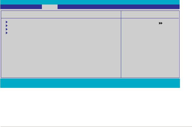
4.7 Boot menu
The Boot menu items allow you to change the system boot options. Select an item
then press <Enter> to display the sub-menu.
Phoenix-Award BIOS CMOS Setup Utility
Main Extreme Tweaker Advanced Power Boot Tools Exit
Boot Device Priority
Select Menu
Removable Drives
Hard Disk Drives
Item Specic Help
Boot Settings Conguration
Security
Select Boot Device
Priority
F1:Help ↑↓ : Select Item -/+: Change Value F5: Setup Defaults
ESC: Exit →←: Select Menu Enter: Select Sub-menu F10: Save and Exit
4.7.1 Boot Device Priority
Phoenix-Award BIOS CMOS Setup Utility
Boot
Boot Device Priority
Select Menu
1st Boot Device [Removable]
Item Specic Help
2nd Boot Device [Hard Disk]
3rd Boot Device [CDROM]
Select Your Boot
4th Boot Device [Disabled]
Device Priority
1st ~ 4th Boot Device [Removable]
These items specify the boot device priority sequence from the available devices.
The number of device items that appears on the screen depends on the number of
devices installed in the system.
Conguration options: [Removable] [Hard Disk] [CDROM] [Disabled]
ASUS Crosshair 4-41

4.7.2 Removable Drives
Phoenix-Award BIOS CMOS Setup Utility
Boot
Removable Drives
Select Menu
1. Floppy Disks
Item Specic Help
1. Floppy Disks
Allows you to assign a removable drive attached to the system.
4.7.3 Hard Disk Drives
Phoenix-Award BIOS CMOS Setup Utility
Boot
Hard Disk Drives
Select Menu
1. SATA 1: XXXXXXXXX
Item Specic Help
1. SATA 1: XXXXXXXXX
Allows you to assign hard disk drives attached to the system.
4-42 Chapter 4: BIOS setup

4.7.4 Boot Settings Conguration
Phoenix-Award BIOS CMOS Setup Utility
Boot
Boot Settings Conguration
Select Menu
Case Open Warning [Enabled]
Item Specic Help
Quick Boot [Enabled]
Boot Up Floppy Seek [Disabled]
Press [Enter] to
Bootup Num-Lock [On]
Typematic Rate Setting [Disabled]
enable or disable.
x Typematic Rate (Chars/Sec) 6
x Typematic Delay (Msec) 250
OS Select For DRAM > 64MB [Non-OS2]
Full Screen LOGO [Enabled]
Halt On [All Errors]
F1:Help ↑↓ : Select Item -/+: Change Value F5: Setup Defaults
ESC: Exit →←: Select Menu Enter: Select Sub-menu F10: Save and Exit
Case Open Warning [Enabled]
Enables or disables the chassis open status feature. Setting to Enabled, clears the
chassis open status. Refer to section “2.8.2 Internal connectors” for setting details.
Conguration options: [Disabled] [Enabled]
Quick Boot [Enabled]
Allows you to enable or disable the system quick boot feature. When Enabled, the
system skips certain tests while booting.
Conguration options: [Disabled] [Enabled]
Boot Up Floppy Seek [Disabled]
Enables or disables the chassis open status feature. Setting to Enabled, clears the
chassis open status. Conguration options: [Disabled] [Enabled]
Bootup Num-Lock [On]
Allows you to select the power-on state for the NumLock.
Conguration options: [Off] [On]
Typematic Rate Setting [Disabled]
Allows you to set the keystroke rate. Enable this item to congure the Typematic
Rate (Chars/Sec) and the Typematic Delay (Msec).
Conguration options: [Disabled] [Enabled]
The items Typematic Rate (Chars/Sec) and Typematic Delay (Msec) become
user-congurable only when the item Typematic Rate Setting is enabled.
ASUS Crosshair 4-43
Typematic Rate (Chars/Sec) [6]
Allows you to select the rate at which a character repeats when you hold a key.
Conguration options: [6] [8] [10] [12] [15] [20] [24] [30]
Typematic Delay (Msec) [250]
Allows you to set the delay before keystrokes begin to repeat.
Conguration options: [250] [500] [750] [1000]
OS Select for DRAM > 64MB [Non-OS2]
Set this item to OS2 only when you are running on an OS/2 operating system with
an installed RAM of greater than 64 MB. Conguration options: [Non-OS2] [OS2]
Full Screen LOGO [Enabled]
Allows you to enable or disable the full screen logo display feature.
Conguration options: [Disabled] [Enabled]
Make sure that the above item is set to [Enabled] if you want to use the ASUS
MyLogo3™ feature.
Halt On [All Errors]
Allows you to set the error report type.
Conguration options: [All Errors] [No Errors] [All, But Keyboard] [All, But Diskette]
[All, But Disk/Key]
4.7.5 Security
Phoenix-Award BIOS CMOS Setup Utility
Boot
Security
Select Menu
Supervisor Password Clear
Item Specic Help
User Password Clear
Password Check [Setup]
Supervisor Password
User Password
These elds allow you to set passwords:
To set a password:
1. Select an item then press <Enter>.
2. Type in a password using a combination of a maximum of eight (8)
alpha-numeric characters, then press <Enter>.
4-44 Chapter 4: BIOS setup

3. When prompted, conrm the password by typing the exact characters again,
then press <Enter>. The password eld setting is changed to Set.
To clear the password:
1. Select the password eld and press <Enter> twice. The following message
appears:
PASSWORD DISABLED !!!
Press any key to continue...
2. Press any key to continue. The password eld setting is changed to Clear.
A note about passwords
The Supervisor password is required to enter the BIOS Setup program
preventing unauthorized access. The User password is required to boot the
system preventing unauthorized use.
Forgot your password?
If you forget your password, you can clear it by erasing the CMOS Real Time
Clock (RTC) RAM. The RAM data containing the password information is
powered by the onboard button cell battery. If you need to erase the CMOS
RAM, refer to section “2.6 Jumper” for instructions.
Password Check
This eld requires you to enter the password before entering the BIOS setup or the
system. Select [Setup] to require the password before entering the BIOS Setup.
Select [System] to require the password before entering the system.
Conguration options: [Setup] [System]
ASUS Crosshair 4-45
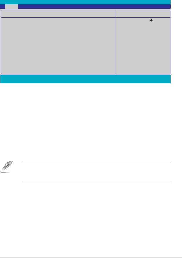
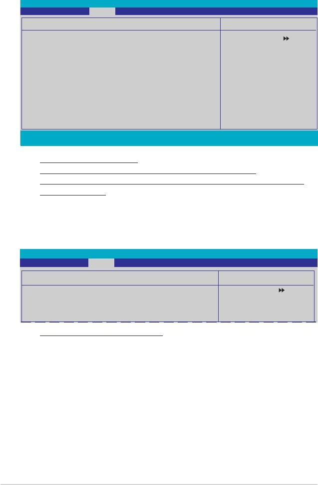
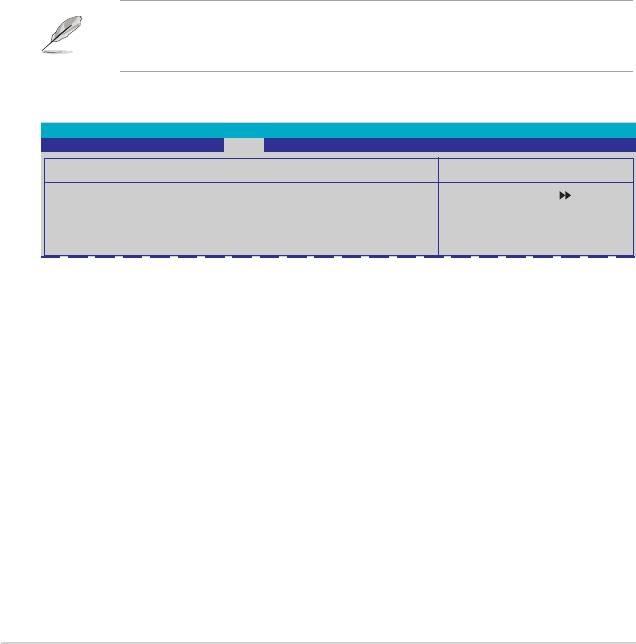
4.8 Tools menu
The Tools menu items allow you to congure options for special functions. Select
an item then press <Enter> to display the sub-menu.
Phoenix-Award BIOS CMOS Setup Utility
Main Extreme Tweaker Advanced Power Boot Tools Exit
ASUS Music Alarm
Select Menu
ASUS O.C. Prole
ASUS EZ Flash 2
Item Specic Help
F1:Help ↑↓ : Select Item -/+: Change Value F5: Setup Defaults
ESC: Exit →←: Select Menu Enter: Select Sub-menu F10: Save and Exit
4.8.1 ASUS Music Alarm
Phoenix-Award BIOS CMOS Setup Utility
Tools
ASUS Music Alarm
Select Menu
ASUS Music Alarm [Disabled]
Item Specic Help
x Alarm Date: Sunday Enabled
x Monday Enabled
Press [Enter] to select.
x Tuesday Enabled
x Wednesday Enabled
x Thursday Enabled
x Friday Enabled
x Saturday Enabled
x Alarm Time (hh:mm) 0 : 0
x Audio CD Drive Primary IDE Master
x Detect CD Enter
x Starting Track N/A
x Repeat Track Disabled
x Length 10 Mins
x Volume 16
F1:Help ↑↓ : Select Item -/+: Change Value F5: Setup Defaults
ESC: Exit →←: Select Menu Enter: Select SubMenu F10: Save and Exit
ASUS Music Alarm [Disabled]
Allows you to enable or disable the ASUS Music Alarm function.
Conguration options: [Disabled] [Enabled]
The succeeding items become user-congurable when you enable the ASUS
Music Alarm.
Alarm Date: Sunday/Monday/Tuesday/Wednesday/Thursday/Friday/
Saturday [Enabled]
Allows you to enable or disable the alarm for a particular day.
Conguration options: [Disabled] [Enabled]
4-46 Chapter 4: BIOS setup
Alarm Time (hh:mm) 0 : 0
Allows you to set the alarm time. Press <Tab> to select the eld, then use <+> or
<-> to change the value. Conguration options: [Disabled] [Enabled]
Audio CD Drive [Primary IDE Master]
Allows you to select the connection conguration of the optical storage device from
which the alarm music will play from.
Conguration options: [Primary IDE Master] [Primary IDE Slave]
Detect CD [Enter]
Press <Enter> to search the CD track number.
Starting Track
Allows you to choose the starting track from the CD from which you would like the
alarm music to play.
Repeat Track [Disabled]
Allows you to enable or disable the repeat track function.
Conguration options: [Disabled] [Single] [All]
Length [10 Mins]
Allows you to set the length of the music alarm.
Conguration options: [10 Mins] [20 Mins] [30 Mins] [1 Hour]
Volume [16]
Allows you to set the volume level of the music alarm.
Conguration options: [01] ~ [32]
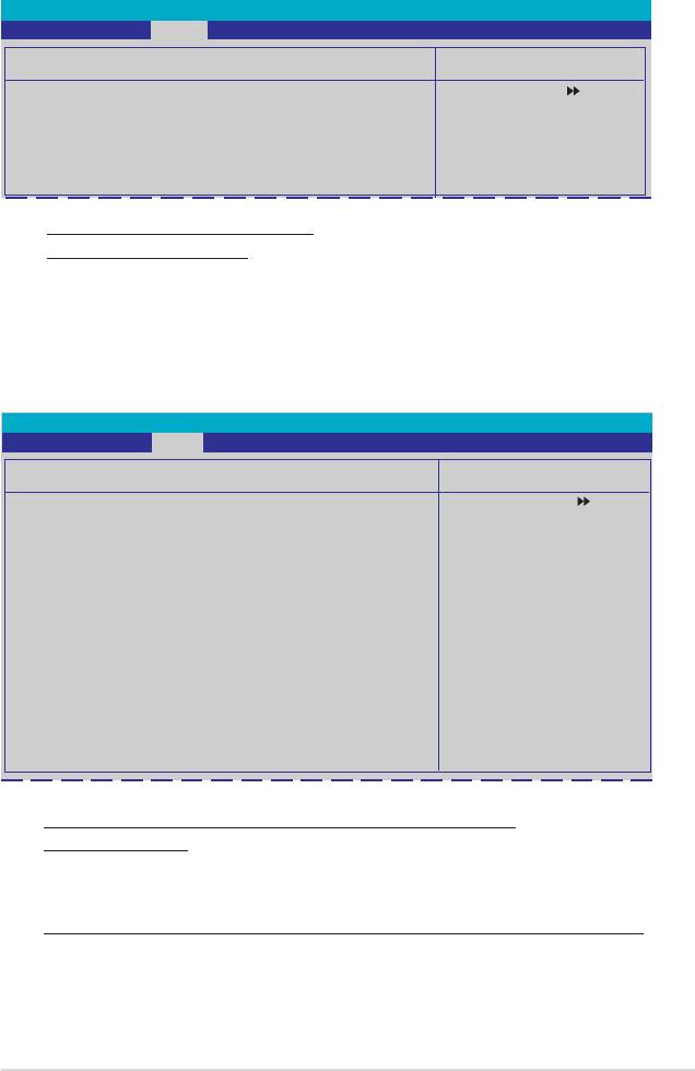
4.8.2 ASUS O.C. Prole
This item allows you to store or load multiple BIOS settings.
Phoenix-Award BIOS CMOS Setup Utility
Tools
ASUS BIOS Prole
Select Menu
Load BIOS Prole
Item Specic Help
Save BIOS Prole
Press [Enter] to select.
Load BIOS Prole
Phoenix-Award BIOS CMOS Setup Utility
Tools
Load BIOS Prole
Select Menu
Load from Prole 1
Item Specic Help
Load from Prole 2
Load from File
Load BIOS Prole from
Prole 1.
ASUS Crosshair 4-47
Load from Prole 1/2
Allows you to load the previous BIOS settings saved in the BIOS Flash. Press
<Enter> to load the le.
Load from File
Allows you to load the previous BIOS le saved in the hard disk/oppy disk/USB
ash disk with the FAT32/16/12 format. Follow the instructions below to load the
BIOS le.
1. Insert the storage devices that contains the “xxx.CMO” le.
2. Turn on the system.
3. Enter BIOS setup program. Go to the “Tools” menu to select “Load from
File.” Press <Enter> then the setup screen will appear.
4. Press <Tab> to switch between drives before the correct “xxx.CMO” le
is found. Then press <Enter> to load the le.
5. A pop-up message will inform you when the loading process nishes.
• Suggest only to update the BIOS le coming from the same memory/CPU
conguration and BIOS version.
• Only the “xxx.CMO” le can be loaded.
Save BIOS Prole
Phoenix-Award BIOS CMOS Setup Utility
Tools
Save BIOS Prole
Select Menu
Save to Prole 1
Item Specic Help
Save to Prole 2
Save to File
Save current BIOS Prole
to Prole 1.
Save to Proe 1/2
Allows you to save the current BIOS le to the BIOS Flash. Press <Enter> to save
the le.
Save to File
Allows you to save the current BIOS le to the hard disk/oppy disk/USB ash disk
with FAT32/16/12 format. Follow the instructions below to save the BIOS le.
1. Insert the storage devices with enough space.
2. Turn on the system.
3. Enter the BIOS setup program. Go to the “Tools” menu to select “Save to
File.” Press <Enter> then the setup screen will appear.
4. Press <Tab> to switch between the drives. Press hot-key <S> to save
the le.
4-48 Chapter 4: BIOS setup
5. Key in the le name. Then press <Enter>.
6. A pop-up message will inform you when the saving process nishes.
ASUSTek O.C. Prole Utility B313
Current CMOS
Update CMOS
BOARD: CROSSHAIR
BOARD: Unknown
VER: 0115
VER: Unknown
DATE: 05/04/2006
DATE: Unknown
PATH: A:\
A:
CMOS backup is done! Press any key to Exit.
Note
[Enter] Select [S] Save [ESC]: Exit
[Tab] Switch [Up/Down/Home/End] Move
The BIOS le will be saved as “xxx.CMO“.
4.8.3 ASUS EZ Flash 2
Allows you to run ASUS EZ Flash 2. When you press <Enter>, a conrmation
message appears. Use the left/right arrow key to select between [Yes] or [No],
then press <Enter> to conrm your choice.
ASUSTek EZ Flash 2 BIOS ROM Utility B311
FLASH TYPE: Winbond W39V080A 8Mb LPC
Current ROM
Update ROM
BOARD: CROSSHAIR
BOARD: Unknown
VER: 0115
VER: Unknown
DATE: 05/04/2006
DATE: Unknown
PATH: A:\
A:
Note
[Enter] Select [S] Save [ESC] Exit
[Tab] Switch [Up/Down/Home/End] Move
ASUS Crosshair 4-49
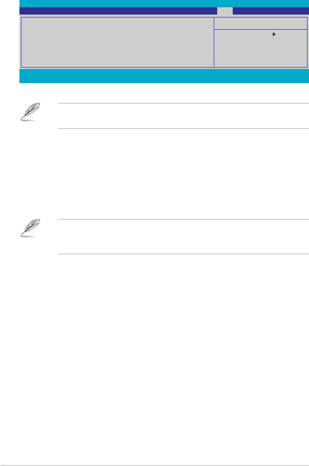
4.9 Exit menu
The Exit menu items allow you to load the optimal or failsafe default values for the
BIOS items, and save or discard your changes to the BIOS items.
Phoenix-Award BIOS CMOS Setup Utility
Main Extreme Tweaker Advanced Power Boot Tools Exit
Exit & Save Changes
Select Menu
Exit & Discard Changes
Load Setup Default
Item Specic Help
Discard Changes
This option save data
to CMOS and exiting
the setup menu.
F1:Help ↑↓ : Select Item -/+: Change Value F5: Setup Defaults
ESC: Exit →←: Select Menu Enter: Select SubMenu F10: Save and Exit
Pressing <Esc> does not immediately exit this menu. Select one of the options
from this menu or <F10> from the legend bar to exit.
Exit & Save Changes
Once you are nished making your selections, choose this option from the Exit
menu to ensure the values you selected are saved to the CMOS RAM. An onboard
backup battery sustains the CMOS RAM so it stays on even when the PC is turned
off. When you select this option, a conrmation window appears. Select YES to
save changes and exit.
If you attempt to exit the Setup program without saving your changes, the
program prompts you with a message asking if you want to save your changes
before exiting. Press <Enter> to save the changes while exiting.
Exit & Discard Changes
Select this option only if you do not want to save the changes that you made to the
Setup program. If you made changes to elds other than System Date, System
Time, and Password, the BIOS asks for a conrmation before exiting.
Load Setup Default
This option allows you to load the default values for each of the parameters on the
Setup menus. When you select this option or if you press <F5>, a conrmation
window appears. Select YES to load default values. Select Exit & Save Changes
or make other changes before saving the values to the non-volatile RAM.
Discard Changes
This option allows you to discard the selections you made and restore the
previously saved values. After selecting this option, a conrmation appears. Select
YES to discard any changes and load the previously saved values.
4-50 Chapter 4: BIOS setup
