Asus Crosshair II Formula: Hardware
Hardware: Asus Crosshair II Formula
This chapter lists the hardware setup
procedures that you have to perform
when installing system components. It
includes description of the jumpers and
connectors on the motherboard.
Hardware
2
information

Chapter summary
2
2.1 Before you proceed ..................................................................... 2-1
2.2 Motherboard overview ................................................................. 2-2
2.3 Central Processing Unit (CPU) ................................................... 2-6
2.4 System memory ......................................................................... 2-12
2.5 Expansion slots .......................................................................... 2-20
2.6 Jumper ........................................................................................ 2-23
2.7 Audio Card and EL I/O Installation ........................................... 2-24
2.8 Connectors ................................................................................. 2-25
ASUS Crosshair
2.1 Before you proceed
Take note of the following precautions before you install motherboard components
or change any motherboard settings.
• Use a grounded wrist strap or touch a safely grounded object or to
a metal object, such as the power supply case, before handling
components to avoid damaging them due to static electricity.
• Hold components by the edges to avoid touching the ICs on them.
• Whenever you uninstall any component, place it on a grounded
antistatic pad or in the bag that came with the component.
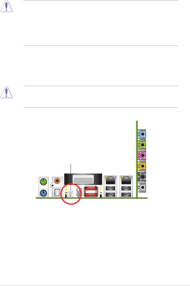
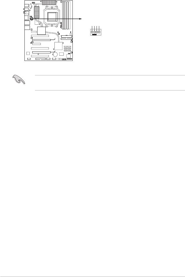
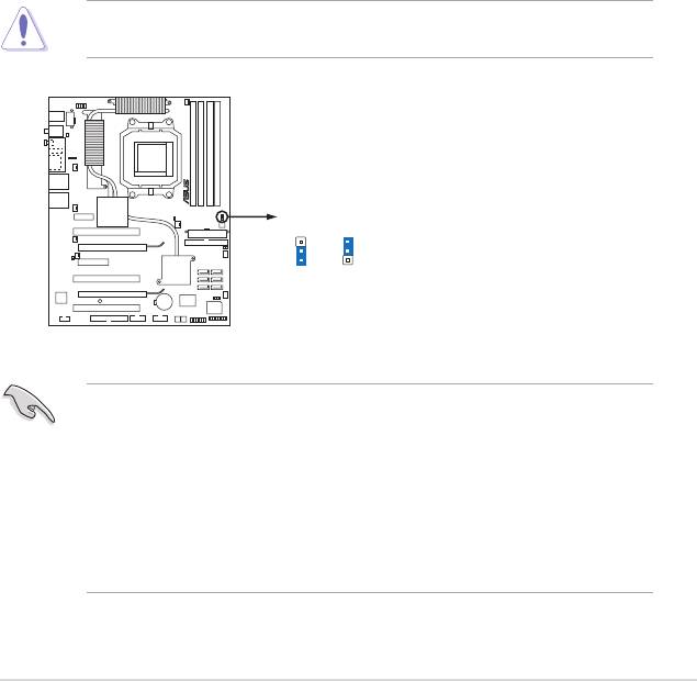
Onboard LED
Blue lights strategically located beside key motherboard connectors allow you
to install components conveniently, even without a ashlight.
Before you install or remove any component, make sure to press the onboard
LED switch rst and the standby power LED is off. Failure to do so may cause
injury or severe damage to the motherboard, peripherals, and/or components.
On Board LED switch
ASUS Crosshair 2-1
2.2 Motherboard overview
Before you install the motherboard, study the conguration of your chassis to
ensure that the motherboard ts into it.
• Make sure to unplug the power cord before installing or removing the
motherboard. Failure to do so can cause you physical injury and damage
motherboard components.
• Remove the lm on the heatsink before installation.
2.2.1 Placement direction
When installing the motherboard, make sure that you place it into the chassis in
the correct orientation. The edge with external ports goes to the rear part of the
chassis as indicated in the image below.
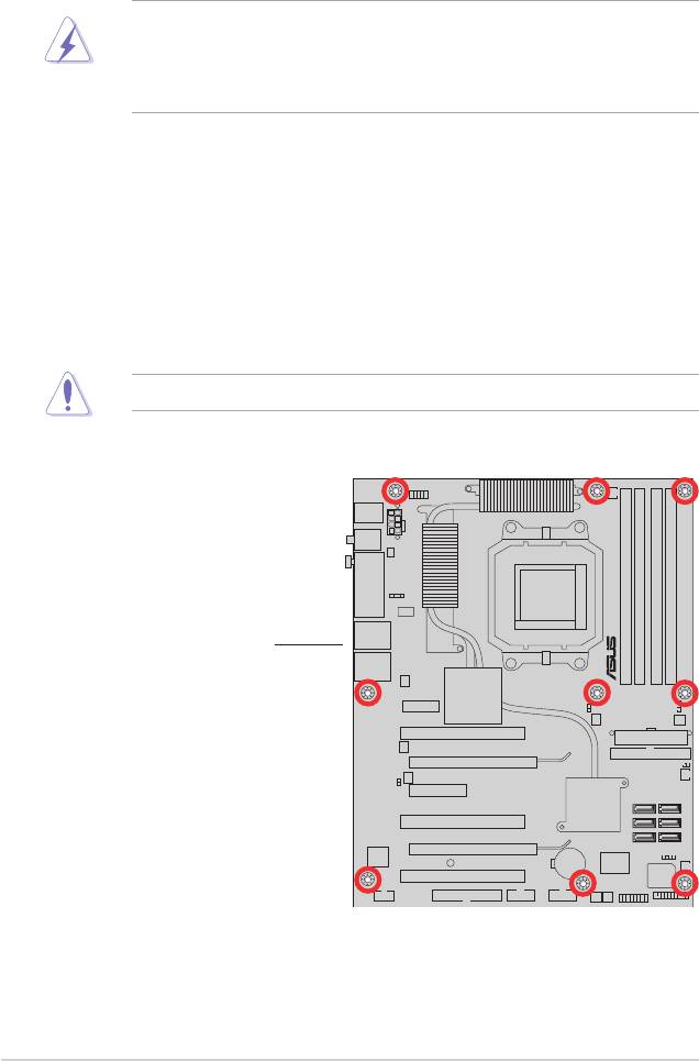
2.2.2 Screw holes
Place nine (9) screws into the holes indicated by circles to secure the motherboard
to the chassis.
Do not overtighten the screws! Doing so can damage the motherboard.
Place this side towards
the rear of the chassis
2-2 Chapter 2: Hardware information
CROSSHAIR
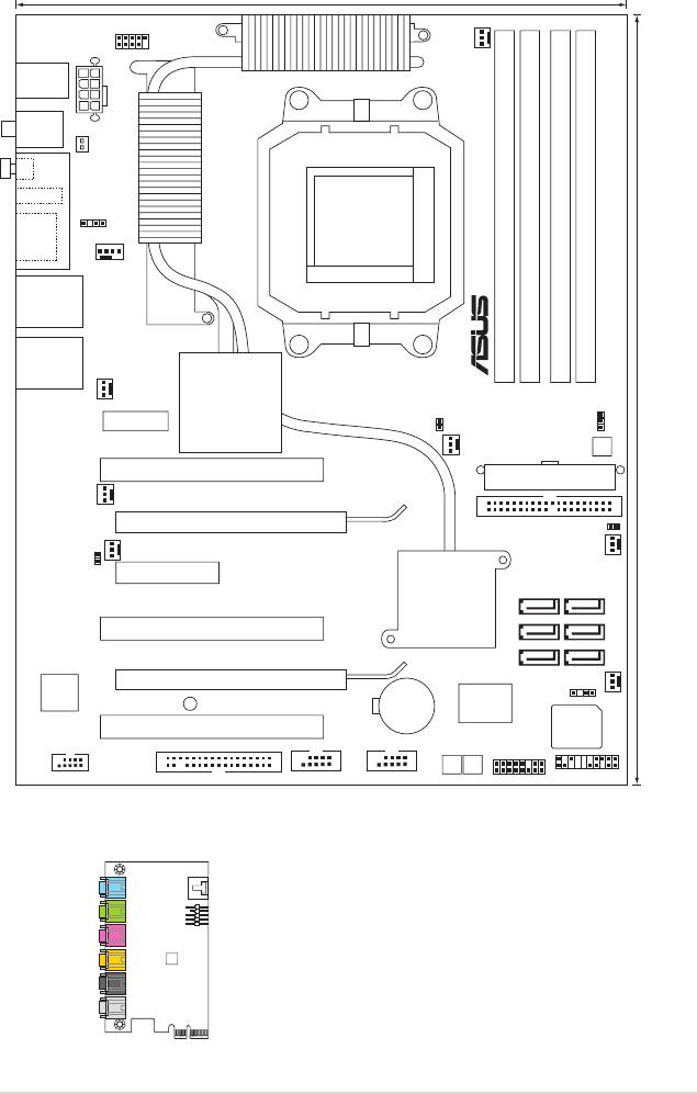
2.2.3 Motherboard layout
ASUS Crosshair 2-3ASUS Crosshair 2-3
24.5cm
WIFI_G_USB910
OPT_FAN5
ATX12V1
SPDIF_OUT
P_ELJ1
O_SW1
O_SW1
IE1394_1
SPDIF_OUT
ESA T A12
CPU_FAN
LAN1_USB12
LAN2_USB34
OPT_F AN4
AUDIO_1
WJ3
CLRTC_EN
OPT_FAN3
O_SW2
PCI1
PCIEX16_1
WJ1
OPT_FAN2
OPT_FAN1
WJ2
PCIEX4_1
SA T A5 SA T A6
PCI2
SA T A3 SA T A4
SA T A1 SA T A2
PCIEX16_2
TSB43AB22A
CHASSIS1
CR2032 3V
Super
SB_PWR
Lithium Cell
F _ _ T N O R F _ A H C N A
CMOS Power
I/O
PCI3
IE1394_2
ADFP1
PANEL
FLOPPY USB78 USB56
PWN_SW RST_SW
(
9.6in
)
)
n i 0 . 2 1
(
PS2/2KBMS
T :Mouse
B:Keyboard
9 3 9 t e k c o
S
DDR2 DIMM_B1 (64 bit, 240-pin module)
DDR2 DIMM_B2 (64 bit, 240-pin module)
DDR2 DIMM_A1 (64 bit, 240-pin module)
DDR2 DIMM_A2 (64 bit, 240-pin module)
m c 5 . 0 3
®
NVIDIA
C51XE
EATXPWR
CHA_REAR_FAN
PRI_IDE
®
NVIDIA
CROSSHAIR
MCP55PXE
8Mb
BIOS
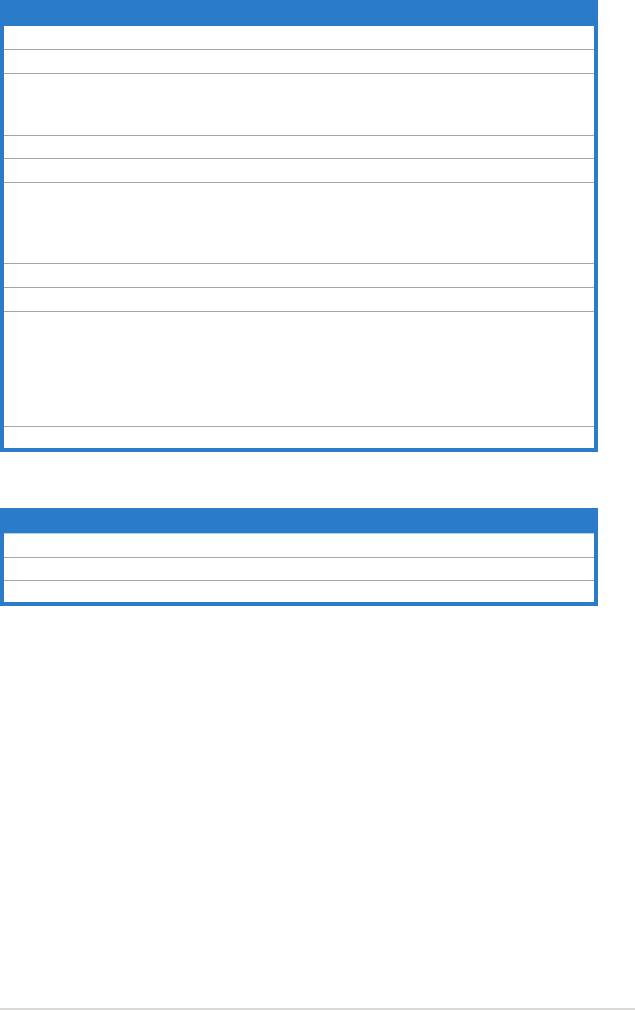
2.2.4 Audio card layout
LCD Poster
SPDIF OUT
1 2
1394
eSATA
LED SW

2.2.5 Layout contents
Slots Page
1. DDR2 DIMM slots 2-12
2. PCI slots 2-22
3. PCI Express x 4 slot 2-22
4. PCI Express x16 slots 2-22
Jumper Page
1. Clear RTC RAM (3-pin CLRTC) 2-23
Rear panel connectors Page
1. PS/2 mouse port (green) 2-25
2. Coaxial S/PDIF Out port 2-25
3. Onboard LED switch 2-25
4. IEEE 1394a port 2-25
5. External SATA ports 2-25
6. LAN 2 (RJ-45) port. 2-26
7. LAN 1 (RJ-45) port 2-26
8. USB 2.0 ports 1 and 2, 3 and 4 2-27
9. Optical S/PDIF Out port 2-27
10. PS/2 keyboard port (purple) 2-27
Supreme FX Page
1. Line In port (light blue) 2-27
2. Line Out port (lime) 2-27
3. Microphone port (pink) 2-27
4. Center/Subwoofer port (orange) 2-27
5. Side Speaker Out port (gray) 2-27
6. Rear Speaker Out port (black) 2-27
2-4 Chapter 2: Hardware information
Internal connectors Page
1. Floppy disk drive connector (34-1 pin FLOPPY) 2-28
2. IDE connector (40-1 pin PRI_IDE) 2-28
®
3. NVIDIA
NF590-SLI Southbridge Serial ATA connectors
2-29
(7-pin SATA1 [blue], SATA2 [blue], SATA3 [blue], SATA4 [blue],
SATA5 [blue], SATA6 [blue])
4. USB connectors (10-1 pin USB56, USB78) 2-30
5. IEEE 1394a port connector (10-1 pin IE1394_2) 2-30
6. CPU, chassis, and optional fan connectors (4-pin CPU_FAN,
2-31
3-pin CHA_REAR_FAN, 3-pin CHA_FRONT_FAN, 3-pin
OPT_FAN1, 3-pin OPT_FAN2, 3-pin OPT_FAN3, 3-pin
OPT_FAN4, 3-pin OPT_FAN5)
7. Chassis intrusion connector (4-1 pin CHASSIS) 2-31
8. ATX power connectors (24-pin EATXPWR, 8-pin EATX12V, 2-32
9. System panel connector (20-pin PANEL)
2-33
•
System power LED (Green 3-pin PLED)
•
Hard disk drive activity LED (Red 2-pin IDE_LED)
•
System warning speaker (Orange 4-pin SPEAKER)
•
ATX power button/soft-off button (Yellow 2-pin PWR)
•
Reset button (Blue 2-pin RESET)
10. Thermo sensor cable connectors (WJ1/2/3, 2-pin) 2-34
Onboard switches Page
1. Clear CMOS switch 2-33
2. Power-on switch 2-33
3. Reset switch 2-34
ASUS Crosshair 2-5
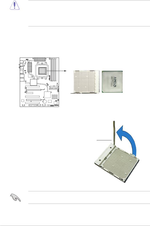
2.3 Central Processing Unit (CPU)
The motherboard comes with a 940-pin AM2 socket designed for the AMD
Athlon™ 64 X2/Athlon™ 64/Athlon™ FX/Sempron™ processor.
The AM2 socket has a different pinout from the 940-pin socket designed for the
AMD Opteron™ processor. Make sure you use a CPU is designed for the AM2
socket. The CPU ts in only one correct orientation. DO NOT force the CPU into
the socket to prevent bending the connectors on the socket and damaging the
CPU!
2.3.1 Installing the CPU
To install a CPU:
1. Locate the CPU socket on the motherboard.
2. Unlock the socket by pressing the
lever sideways, then lift it up to a
90º angle.
Socket lever
Make sure that the socket lever is lifted up to 90º angle; otherwise, the CPU will
not t in completely.
2-6 Chapter 2: Hardware information
CROSSHAIR
CROSSHAIR CPU AM2 940
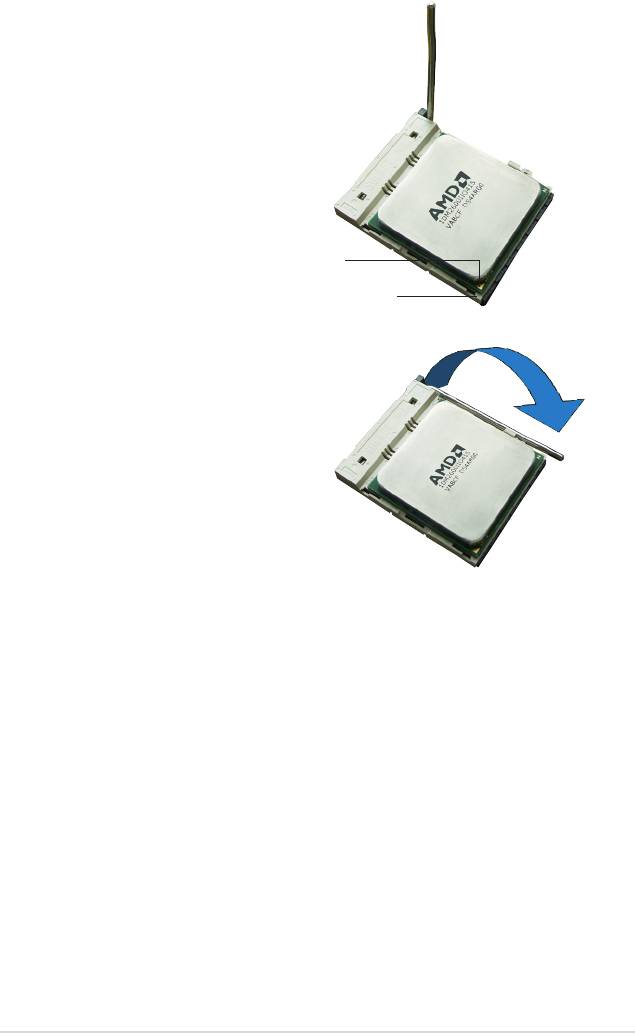
3. Position the CPU above the socket
such that the CPU corner with the
gold triangle matches the socket
corner with a small triangle.
4. Carefully insert the CPU into the
socket until it ts in place.
Gold triangle
Small triangle
5. When the CPU is in place, push
down the socket lever to secure the
CPU. The lever clicks on the side tab
to indicate that it is locked.
6. Install a CPU heatsink and fan
following the instructions that came
with the heatsink package.
ASUS Crosshair 2-7
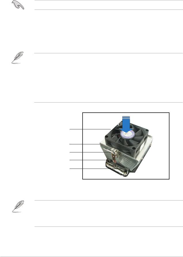
2.3.2 Installing the heatsink and fan
The AMD Athlon™ 64FX/Athlon™ 64/Athlon™ 64 X2/Sempron™ processor
requires a specially designed heatsink and fan assembly to ensure optimum
thermal condition and performance.
Make sure that you use only AMD-certied heatsink and fan assembly.
To install the CPU heatsink and fan:
1. Place the heatsink on top of the installed CPU, making sure that the heatsink
ts properly on the retention module base.
•
The retention module base is already installed on the motherboard
upon purchase.
•
You do not have to remove the retention module base when
installing the CPU or installing other motherboard components.
•
If you purchased a separate CPU heatsink and fan assembly, make
sure that a Thermal Interface Material is properly applied to the CPU
heatsink or CPU before you install the heatsink and fan assembly.
CPU fan
CPU heatsink
Retention bracket lock
Retention bracket
Retention module base
Your boxed CPU heatsink and fan assembly should come with installation
instructions for the CPU, heatsink, and the retention mechanism. If the
instructions in this section do not match the CPU documentation, follow the
latter.
2-8 Chapter 2: Hardware information
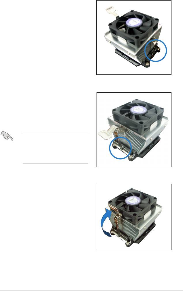
2. Attach one end of the retention bracket
to the retention module base.
3. Align the other end of the retention
bracket (near the retention bracket
lock) to the retention module base.
A clicking sound denotes that the
retention bracket is in place.
Make sure that the fan and
heatsink assembly perfectly ts
the retention mechanism module
base, otherwise you cannot snap
the retention bracket in place.
4. Push up the retention bracket lock on
the retention mechanism to secure the
heatsink and fan to the module base.
ASUS Crosshair
2-9
5. When the fan and heatsink assembly is in place, connect the CPU fan cable
to the connector on the motherboard labeled CPU_FAN.
Do not forget to connect the CPU fan connector! Hardware monitoring errors
can occur if you fail to plug this connector.
2-10
Chapter 2: Hardware information
CPU_FAN
CPU_FAN
GND
+12V
Rotation
RPM adjustment
CROSSHAIR
CROSSHAIR CPU fan connector
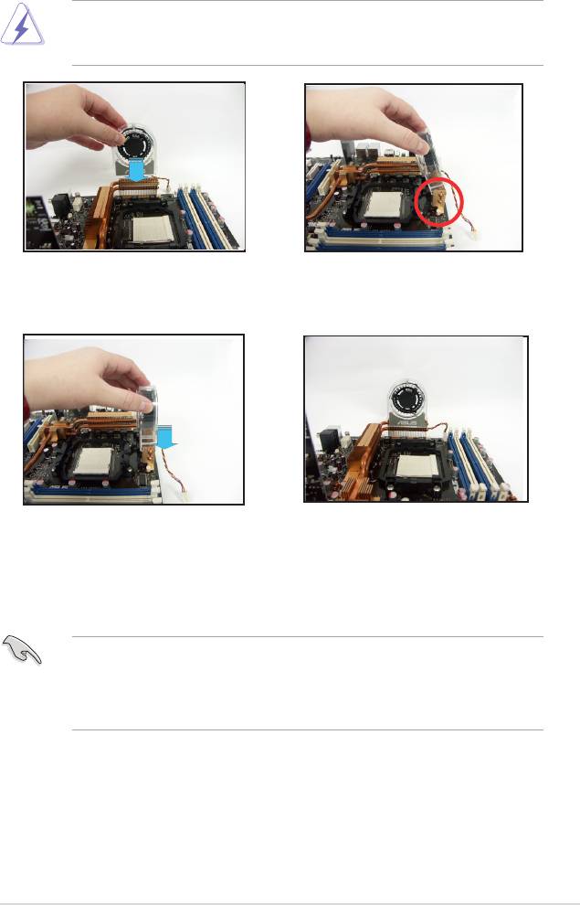
2.3.3 Installing the optional fan
Install the optional fan only if you are using a passive cooler or a water cooler.
Installing the optional fan with an active CPU cooler will interfere with the airow
and destabilize the system.
1. Position the fan above the pipe
2. Fit the grooved edge to the
and heatsink assembly.
heatsink.
3. Carefully push down the fan until
4. The above photo shows the fans
it snugly ts the heatsink, then
installed on the motherboard.
connect the fan cables.
•
Plug the optional fan cables to any of the OPT FAN1~5 connectors on the
motherboard.
•
Make sure the optional fan is installed correctly to prevent damage to the
fan and motherboard components.
ASUS Crosshair
2-11
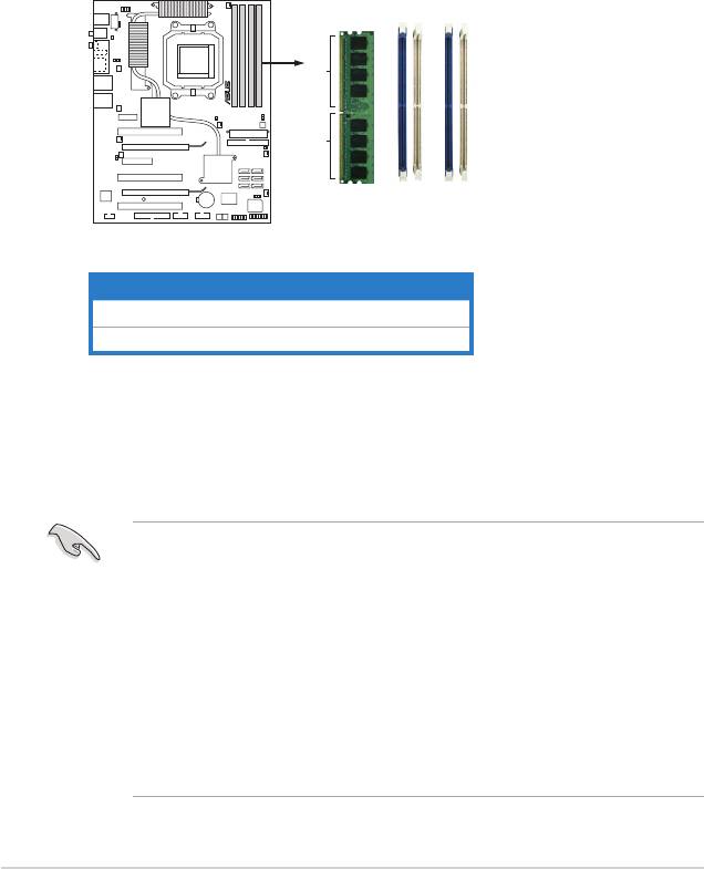
2.4 System memory
2.4.1 Overview
The motherboard comes with four Double Data Rate 2 (DDR2) Dual Inline Memory
Modules (DIMM) sockets.
A DDR2 module has the same physical dimensions as a DDR DIMM but has a
240-pin footprint compared to the 184-pin DDR DIMM. DDR2 DIMMs are notched
differently to prevent installation on a DDR DIMM socket.
The gure illustrates the location of the DDR2 DIMM sockets:
Channel Sockets
Channel A DIMM_A1 and DIMM_A2
Channel B DIMM_B1 and DIMM_B2
2-12
Chapter 2: Hardware information
1B_MMID
2B_MMID
1A_MMID
2A_MMID
112 Pins 128 Pins
CROSSHAIR
CROSSHAIR 240-pin DDR DIMM Sockets
2.4.2 Memory congurations
You may install 256 MB, 512 MB, 1 GB, and 2 GB unbuffered ECC/non-ECC
DDR2 DIMMs into the DIMM sockets.
®
• If you installed Windows
XP 32-bit version operating system, we
®
recommend that you install less than 3 GB of total memory. For Windows
XP 64-bit version operating system, the maxium support is 8 GB of total
memory.
• For dual-channel conguration, the total size of memory module(s) installed
per channel must be the same (DIMM_A1 + DIMM_A2 = DIMM_B1 +
DIMM_B2).
• Always install DIMMs with the same CAS latency. For optimum
compatibility, we recommend that you obtain memory modules from the
same vendor. Refer to the DDR2 Qualied Vendors List on the next page
for details.

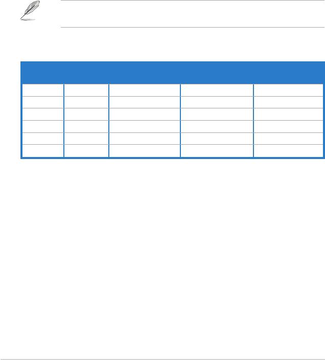
Qualied Vendors Lists (QVL)
DDR2-800 MHz capability
Qualied Vendors List (QVL) Standard table for user manual
DIMM Support
Chip
SS/
Size Vendor Chip No. CL
Brand
DS Part No.
A* B* C*
512MB KINGSTON Heat-Sink Package N/A N/A SS KHX6400D2/512
512MB KINGSTON K4T51083QC N/A N/A SS KVR800D2N5/512 V V V
1024MB KINGSTON K4T51083QC N/A N/A DS KVR800D2N5/1G V
256MB SAMSUNG K4T56083QF-ZCE7 N/A N/A SS M378T3253FZ3-CE7
256MB SAMSUNG K4T56083QF-ZCE7(ECC) N/A N/A SS M391T3253FZ3-CE7 V V V
512MB SAMSUNG EDD339XX N/A N/A SS M378T6553CZ3-CE7
512MB Inneon HYB18T256800AF25 N/A N/A DS HYS64T64520HU-2.5-A V V
512MB Inneon HYB18T256800AF25F N/A N/A DS HYS64T64020HU-25F-A V V
512MB Hynix HY5PS12821BFP-S5 N/A N/A SS HYMP564U64BP8-S5 V V
1024MB Hynix HY5PS12821BFP-S5 N/A N/A DS HYMP512U64BP8-S5 V V
512MB MICRON 5JAIIZ9DQQ N/A N/A SS MT8HTF6464AY-80EA3 V V V
1024MB MICRON 5JAIIZ9DQQ N/A N/A DS MT16HTF12864AY-80EA3 V V V
512MB MICRON 5ZD22D9GKX N/A N/A SS MT8HTF6464AY-80ED4 V V V
1024MB MICRON 5ZD22D9GKX N/A N/A DS MT16HTF12864AY-80ED4 V V
512MB MICRON 6CD22D9GKX N/A N/A SS MT8HTF6464AY-80ED4 V V
1024MB MICRON 6CD22D9GKX N/A N/A DS MT16HTF12864AY-80ED4 V V
512MB CORSAIR Heat-Sink Package N/A N/A SS CM2X512A-6400
1024MB CORSAIR Heat-Sink Package N/A N/A DS CM2X1024-6400PRO
1024MB CORSAIR Heat-Sink Package N/A N/A DS CM2X1024-6400C4 V
256MB A-DATA E2508AB-GE-E N/A N/A SS M20EL6F3G3170A1D0Z
256MB A-DATA E2508AB-GE-E N/A N/A SS M20EL6F3G3160A1D0Z
256MB A-DATA E2508AB-GE-E N/A N/A SS M2OEL6F3G3160A1D0Z V V
512MB A-DATA E2508AB-GE-E N/A N/A DS M2OEL6F3H4170A1D0Z
512MB A-DATA N/A N/A N/A SS M2OAD6G3H3160J1E52
512MB A-DATA AD29608A8A-25EG N/A N/A SS M20AD6G3H3160I1E5E
256MB Apacer E2508AB-GE-E N/A N/A SS 78.81091.420 V
512MB Apacer E2508AB-GE-E N/A N/A DS 78.91091.420
512MB Crucial Heat-Sink Package N/A N/A SS BL6464AA804.8FA
(Continued on the next page)
ASUS Crosshair
2-13
DDR2-800 MHz capability
Qualied Vendors List (QVL) Standard table for user manual
DIMM Support
Chip
SS/
Size Vendor Chip No. CL
Brand
DS Part No.
A* B* C*
1024MB Crucial Heat-Sink Package N/A N/A DS BL12864AA804.16FA V V
256MB TwinMOS E2508AB-GE-E N/A N/A SS 8G-24IK2-EBT
512MB OCZ Heat-Sink Package N/A N/A SS OCZ28001024EBDCPE-K
512MB Elixir N2TU51280AE-25C N/A N/A SS M2Y51264TU88A2B-25C
512MB NANYA NT5TU64M8AE-25C N/A N/A SS NT512T64U88A1BY-25C
512MB NANYA NT5TU64M8BE-25C N/A N/A SS NT512T64U88B0BY-25C
1024MB NANYA NT5TU64M8BE-25C N/A N/A DS NT1GT64U8HB0BY-25C
1024MB GEIL Heat-Sink Package N/A N/A DS GX22GB6400UDC
SS - Single-sided DS - Double-sided
DIMM support:
A - Supports one module inserted into either slot, in Single-channel memory conguration.
B - Supports one pair of modules inserted into either Channel A or Channel B as one pair of
Dual-channel memory conguration.
C - Supports four modules inserted into the yellow and black slots as two pairs of
Dual-channel memory conguration.
Visit the ASUS website for the latest DDR2-800 MHz QVL.
2-14
Chapter 2: Hardware information

DDR2-667 MHz capability
Qualied Vendors List (QVL) Standard table for user manual
DIMM support
SS/
Size Vendor Chip No. CL Brand
DS Part No.
A* B* C*
512MB KINGSTON E5108AE-6E-E N/A N/A SS KVR667D2N5/512 V V V
1024MB KINGSTON E5108AE-6E-E N/A N/A DS KVR667D2N5/1G V
512MB KINGSTON E5108AE-6E-E N/A N/A SS KVR667D2E5/512 V V V
256MB KINGSTON HYB18T256800AF3 N/A N/A SS KVR667D2N5/256 V V V
256MB SAMSUNG K4T56083QF-ZCE6 N/A N/A SS M378T3253FZ0-CE6 V V V
512MB SAMSUNG K4T56083QF-ZCE6 N/A N/A DS M378T6453FZ0-CE6 V V V
256MB SAMSUNG K4T56083QF-ZCE6(ECC) N/A N/A SS M391T3253FZ0-CE6 V V
512MB SAMSUNG K4T56083QF-ZCE6(ECC) N/A N/A DS M391T6453FZ0-CE6 V V
256MB SAMSUNG K4T51163QC-ZCE6 N/A N/A SS M378T3354CZ0-CE6 V V
512MB SAMSUNG ZCE6K4T51083QC N/A N/A SS M378T6553CZ0-CE6 V V V
1024MB SAMSUNG ZCE6K4T51083QC N/A N/A DS M378T2953CZ0-CE6 V V V
512MB MICRON 4VB41D9CZM N/A N/A DS MT16HTF6464AY-667B4 V V V
256MB Inneon HYB18T512160AF-3S N/A N/A SS HYS64T32000HU-3S-A V V V
512MB Inneon HYB18T512800AF3S N/A N/A SS HYS64T64000HU-3S-A V V V
1024MB Inneon HYB18T512800AF3S N/A N/A DS HYS64T128020HU-3S-A V V
256MB Inneon HYB18T256800AF3S(ECC) N/A N/A SS HYS72T32000HU-3S-A V V
512MB Inneon HYB18T512800AF3S(ECC) N/A N/A SS HYS72T64000HU-3S-A V V V
1024MB Inneon HYB18T512800AF3S(ECC) N/A N/A DS HYS72T128020HU-3S-A V V V
512MB Inneon HYB18T512800BF3S(ECC) N/A N/A SS HYS72T64000HU-3S-B V V V
1024MB Inneon HYB18T512800BF3S(ECC) N/A N/A DS HYS72T128020HU-3S-B V V V
256MB Inneon HYB18T512160BF-3S N/A N/A SS HYS64T32000HU-3S-B V V V
512MB Inneon HYB18T512800BF3S N/A N/A SS HYS64T64000HU-3S-B V V V
1024MB Inneon HYB18T512800BF3S N/A N/A DS HYS64T128020HU-3S-B V V V
512MB Hynix HY5PS12821AFP-Y5 N/A N/A SS HYMP564U64AP8-Y5 V V V
1024MB Hynix HY5PS12821AFP-Y5 N/A N/A DS HYMP512U64AP8-Y5 V V V
1024MB Hynix HY5PS1G831FP-Y5(ECC) N/A N/A SS HYMP112U72P8-Y5 V
512MB Hynix HY5PS12821AFP-Y5(ECC) N/A N/A SS HYMP564U72AP8-Y5 V
1024MB Hynix HY5PS12821AFP-Y5(ECC) N/A N/A DS HYMP512U72AP8-Y5 V V V
512MB Hynix HY5PS12821AFP-Y4 N/A N/A SS HYMP564U64AP8-Y4 V V V
1024MB Hynix HY5PS12821AFP-Y4 N/A N/A DS HYMP512U64AP8-Y4 V V V
512MB Hynix HY5PS12821AFP-Y4(ECC) N/A N/A SS HYMP564U72AP8-Y4 V V V
1024MB Hynix HY5PS12821AFP-Y4(ECC) N/A N/A DS HYMP512U72AP8-Y4 V V V
256MB ELPIDA E2508AB-6E-E N/A N/A SS EBE25UC8ABFA-6E-E V
512MB ELPIDA E5108AE-6E-E N/A N/A SS EBE51UD8AEFA-6E-E V V V
1024MB ELPIDA Engineering Sample N/A N/A DS EBE11UD8AEFA-6E-E V
512MB crucial Heat-Sink Package N/A N/A DS BL6464AA664.16FB V V V
(Continued on the next page)
ASUS Crosshair
2-15
DDR2-667 MHz capability
Qualied Vendors List (QVL) Standard table for user manual
DIMM Support
Chip
SS/
Size Vendo Chip No. CL
Brand
DS Part No.
A* B* C*
1024MB crucial Heat-Sink Package N/A N/A DS BL12864AA664.16FA V V V
512MB crucial Heat-Sink Package N/A N/A DS BL6464AL664.16FB V V V
1024MB crucial Heat-Sink Package N/A N/A DS BL12864AL664.16FA V V
512MB crucial Heat-Sink Package N/A N/A DS BL6464AA663.8FA V V
1024MB crucial Heat-Sink Package N/A N/A DS BL12864AA663.16FA
512MB Kingmax E5108AE-6E-E N/A N/A SS KLCC28F-A8EB5 V V V
1024MB Kingmax E5108AE-6E-E N/A N/A DS KLCD48F-A8EB5
512MB Apacer E5108AE-6E-E N/A N/A SS 78.91092.420
1024MB Apacer E5108AE-6E-E N/A N/A DS 78.01092.420
512MB A-DATA E5108AE-6E-E N/A N/A SS M20EL5G3H3160B1C0Z V V V
512MB A-DATA AD29608A8B-3EG N/A N/A SS M20AD5Q3H3163J1C52
512MB Transcend E5108AE-6E-E N/A N/A SS TS64MLQ64V6J V V V
1024MB Transcend E5108AE-6E-E N/A N/A DS TS128MLQ64V6J V V
512MB TwinMOS E5108AE-GE-E N/A N/A SS 8G-25JK5-EBT
512MB GEIL Heat-Sink Package N/A N/A SS GX21GB5300UDC
512MB GEIL Heat-Sink Package N/A N/A SS GX21GB5300DC
256MB NANYA NT5TU32M16AG-3C N/A N/A SS NT256T64UH4A0FY-3C
512MB NANYA NT5TU64M8AE-3C N/A N/A SS NT512T64U88A0BY-3C
512MB NANYA NT5TU64M8BE-3B N/A N/A SS NT512T64U88B0BY-3C
1024MB NANYA NT5TU64M8BE-3B N/A N/A DS NT1GT64U8HB0BY-3C
512MB Elixir N2TU51280AF-3C N/A N/A SS M2U51264TU88A0F-3C
1024MB Elixir N2TU51280AF-3C N/A N/A DS M2U1G64TU8HA2F-3C
512MB OCZ Heat-Sink Package N/A N/A SS OCZ26671024EBDCPE-K
1024MB OCZ Heat-Sink Package N/A N/A DS OCZ26672048EBDCPE-K
512MB OCZ Heat-Sink Package N/A N/A SS OCZ2P6671GK
1024MB PQI E5108AE-5C-E N/A N/A DS MEAD-403LA
512MB WINTEC 4UAI2D9CRZ N/A N/A SS 39127282
1024MB WINTEC 4WAIID9CWX N/A N/A DS 39137282
512MB MDT 18D51280D-30518 N/A N/A SS M512-667-8
1024MB MDT 18D51280D-30528 N/A N/A DS M924-667-16
512MB Kingbox DD2640800-667 N/A N/A SS N/A
1024MB Kingbox DD2640800-667 N/A N/A DS N/A
SS - Single-sided DS - Double-sided
DIMM support:
A - Supports one module inserted into either slot, in Single-channel memory conguration.
B - Supports one pair of modules inserted into either Channel A or Channel B as one pair of
Dual-channel memory conguration.
C - Supports four modules inserted into the yellow and black slots as two pairs of
Dual-channel memory conguration.
Visit the ASUS website for the latest DDR2-667 MHz QVL.
2-16
Chapter 2: Hardware information

DDR2-533 MHz capability
Qualied Vendors List (QVL) Standard table for user manual
DIMM Support
Chip
SS/
Size Vendor Chip No. CL
Brand
DS Part No.
A* B* C*
256MB KINGSTON E5116AF-5C-E N/A N/A SS KVR533D2N4/256 V V V
512MB KINGSTON HYB18T512800AF37 N/A N/A SS KVR533D2N4/512 V V V
1024MB KINGSTON 5YDIID9GCT N/A N/A DS KVR533D2N4/1G V V V
512MB SAMSUNG K4T51083QB-GCD5 N/A N/A SS M378T6553BG0-CD5 V
256MB SAMSUNG K4T56083QF-GCD5 N/A N/A SS M378T3253FG0-CD5 V V V
512MB SAMSUNG K4T56083QF-GCD5 N/A N/A DS M378T6453FG0-CD5 V V V
512MB SAMSUNG K4T56083QF-GCD5(ECC) N/A N/A DS M391T6453FG0-CD5 V V V
1024MB SAMSUNG K4T51083QB-GCD5(ECC) N/A N/A DS M391T2953BG0-CD5 V V V
256MB MICRON 4DBIIZ9BQT N/A N/A SS N/A V V V
512MB Inneon HYB18T512800AF3(ECC) N/A N/A SS HYS72T64000HU-3.7-A
512MB Inneon HYB18T512800AC37 N/A N/A SS HYS64T64000GU-3.7-A V V
256MB Inneon HYB18T512160AF-3.7 N/A N/A SS HYS64T32000HU-3.7-A V V V
512MB Inneon HYB18T512800AF37 N/A N/A SS HYS64T64000HU-3.7-A V V V
1024MB Inneon HYB18T512800AF37 N/A N/A DS HYS64T128020HU-3.7-A V V V
2048MB Inneon HYB18T1G800AF-3.7 N/A N/A DS HYS64T256020HU-3.7-A V V V
256MB Inneon HYB18T5121608BF-3.7 N/A N/A SS HYS64T32000HU-3.7-B V V V
512MB Inneon HYB18T512800BF37 N/A N/A SS HYS64T64000HU-3.7-B V V V
1024MB Inneon HYB18T512800BF37 N/A N/A DS HYS64T128020HU-3.7-B V V V
256MB Inneon HYB18T256800AF37(ECC) N/A N/A SS HYS72T32000HU-3.7-A V V V
1024MB Inneon HYB18T512800AF37(ECC) N/A N/A DS HYS72T128020HU-3.7-A V V
512MB Hynix HY5PS12821F-C4 N/A N/A SS HYMP564U648-C4 V V V
512MB Hynix HY5PS12821F-C4(ECC) N/A N/A SS HYMP564U728-C4 V V V
1024MB Hynix HY5PS12821F-C4 N/A N/A DS HYMP512U648-C4 V V V
1024MB Hynix HY5PS12821F-C4(ECC) N/A N/A DS HYMP512U728-C4 V V V
1024MB Hynix HY5PS12821F-E3(ECC) N/A N/A DS HYMP512U728-C4
512MB Hynix HY5PS12821FP-C4(ECC) N/A N/A SS HYMP564U728-C4 V V V
1024MB Hynix HY5PS12821FP-C4 N/A N/A DS HYMP512U648-C4 V V
512MB Hynix HY5PS12821AFP-C3 N/A N/A SS HYMP564U64AP8-C3 V V V
1024MB Hynix HY5PS12821AFP-C3 N/A N/A DS HYMP512U64AP8-C3 V V V
512MB ELPIDA E5108AB-5C-E(ECC) N/A N/A SS EBE51ED8ABFA-5C-E V V V
512MB ELPIDA E5108AB-5C-E N/A N/A SS EBE51UD8ABFA-5C V V V
512MB ELPIDA E5108AB-5C-E N/A N/A SS EBE51UD8ABFA-5C-E V V V
1024MB ELPIDA E5108AB-5C-E N/A N/A DS EBE11UD8ABFA-5C-E V V
2048MB ELPIDA E1108AA-5C-E N/A N/A DS EBE21EE8AAFA-5C-E V
256MB CORSAIR MIII0051832M8CEC N/A N/A SS VS256MB533D2 V V
512MB CORSAIR MI110052432M8CEC N/A N/A DS VS512MB533D2 V V
256MB Apacer E5116AB-5C-E N/A N/A SS 78.81077.420 V V V
256MB KINGMAX E5116AB-5C-E N/A N/A SS KLBB68F-36EP4 V V
(Continued on the next page)
ASUS Crosshair
2-17

DDR2-533 MHz capability
Qualied Vendors List (QVL) Standard table for user manual
DIMM Support
Chip
SS/
Size Vendor Chip No. CL
Brand
DS Part No.
A* B* C*
512MB KINGMAX E5108AE-5C-E N/A N/A SS KLBC28F-A8EB4 V V V
1024MB KINGMAX E5108AE-5C-E N/A N/A DS KLBD48F-A8EB4 V V V
512MB KINGMAX KKEA88E4AAK-37 N/A N/A SS KLBC28F-A8KE4 V V V
1024MB KINGMAX 5MB22D9DCN N/A N/A DS KLBD48F-A8ME4 V V V
512MB Transcend K4T51083QB-GCD5 N/A N/A SS TS64MLQ64V5J V V V
1024MB Transcend K4T51083QB-GCD5 N/A N/A DS TS128MLQ64V5J V V V
256MB CENTURY K4T56083QF-GCD5 N/A N/A SS 25V6S8SSD5F4-K43
512MB CENTURY E5108AB-5C-E N/A N/A SS 25V2H8EL5CB4-J43
1024MB CENTURY E5108AB-5C-E N/A N/A DS 25V0H8EL5CB4-J45
1024MB CENTURY E5108AB-5C-E N/A N/A DS 25VOH8EL5C
256MB elixir N2TU51216AF-37B N/A N/A SS M2U25664TUH4A0F-37B
512MB elixir N2TU51280AF-37B N/A N/A SS M2U51264TU88A0F-37B
256MB Aeneon AET960UD00-37C88X N/A N/A SS AET560UD00-370A98X
512MB Aeneon AET960UD00-37C88X N/A N/A SS AET660UD00-370A98X
512MB Aeneon AET93F370AG0513 N/A N/A SS AET660UD00-370A98X
256MB Aeneon AET94F370A N/A N/A SS AET560UD00-370A98Z
256MB Aeneon AET94F370A N/A N/A SS AET560UD00-370A98X
512MB Aeneon AET93F370A N/A N/A SS AET660UD00-370A98Z
512MB Aeneon AET93F370A N/A N/A SS AET660UD00-370A98X
512MB Aeneon AET93F370 N/A N/A SS AET660UD00-370A98X
1024MB Aeneon AET93F370A N/A N/A DS AET760UD00-370A98X
256MB NANYA NT5TU32M16AF-37B N/A N/A SS NT256T64UH4A0F-37B
512MB NANYA NT5TU64M8AF-37B N/A N/A SS NT512T64U88A0F-37B
512MB NANYA NT5TU64M8AF-37B(ECC) N/A N/A SS NT512T72U89A0F-37B
1024MB NANYA NT5TU64M8AF-37B N/A N/A DS NT1GT64U8HA0F-37B
1024MB PQI 64MX8D2-E N/A N/A DS MEAB-323LA
512MB PQI 64MX8D2-E N/A N/A SS MEAB-423LA
512MB TwinMOS K4T51083QB-GCD5 N/A N/A SS 8D-22JB5-K2T
256MB SimpleTech 858S032F25A N/A N/A SS SVM-42DR2/256
512MB SimpleTech 858S064F25A N/A N/A SS SVM-42DR2/512
1024MB Patriot Heat-Sink Package N/A N/A SS PDC21G5600+XBLK
512MB MDT 18D51280D-3.70S20 N/A N/A SS M512-533-8
1024MB MDT 18D51280D-3.70448 N/A N/A DS M924-533-16
Side(s): SS - Single-sided DS - Double-sided
DIMM support:
A - Supports one module inserted into either slot, in Single-channel memory conguration.
B - Supports one pair of modules inserted into either Channel A or Channel B as one pair of
Dual-channel memory conguration.
C - Supports two pairs of modules inserted into the yellow and black slots as two pairs of
Dual-channel memory conguration.
Visit the ASUS website for the latest DDR2-533 MHz QVL.
2-18
Chapter 2: Hardware information
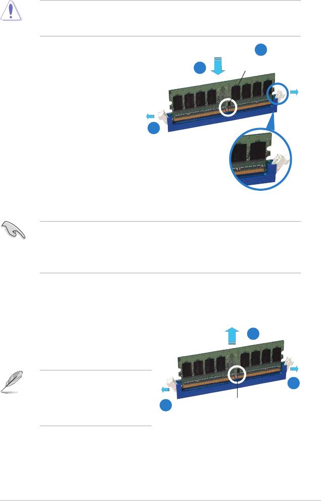
2.4.3 Installing a DIMM
Unplug the power supply before adding or removing DIMMs or other
system components. Failure to do so can cause severe damage to both the
motherboard and the components.
2
To install a DIMM:
DDR2 DIMM notch
3
1. Unlock a DIMM socket by
pressing the retaining clips
outward.
2. Align a DIMM on the socket
such that the notch on the DIMM
matches the break on the socket.
1
3. Firmly insert the DIMM into the
socket until the retaining clips
snap back in place and the
DIMM is properly seated.
Unlocked retaining clip
• A DDR2 DIMM is keyed with a notch so that it ts in only one direction. Do
not force a DIMM into a socket to avoid damaging the DIMM.
• The DDR2 DIMM sockets do not support DDR DIMMs. DO not install DDR
DIMMs to the DDR2 DIMM sockets.
2.4.4 Removing a DIMM
To remove a DIMM:
2
1. Simultaneously press the retaining
clips outward to unlock the DIMM.
Support the DIMM lightly with
1
your ngers when pressing the
retaining clips. The DIMM might
1
DDR2 DIMM notch
get damaged when it ips out
with extra force.
2. Remove the DIMM from the socket.
ASUS Crosshair
2-19

2.5 Expansion slots
In the future, you may need to install expansion cards. The following sub-sections
describe the slots and the expansion cards that they support.
Make sure to unplug the power cord before adding or removing expansion
cards. Failure to do so may cause you physical injury and damage motherboard
components.
2.5.1 Installing an expansion card
To install an expansion card:
1. Before installing the expansion card, read the documentation that came with
it and make the necessary hardware settings for the card.
2. Remove the system unit cover (if your motherboard is already installed in a
chassis).
3. Remove the bracket opposite the slot that you intend to use. Keep the screw
for later use.
4. Align the card connector with the slot and press rmly until the card is
completely seated on the slot.
5. Secure the card to the chassis with the screw you removed earlier.
6. Replace the system cover.
2.5.2 Conguring an expansion card
After installing the expansion card, congure the it by adjusting the software
settings.
1. Turn on the system and change the necessary BIOS settings, if any. See
Chapter 4 for information on BIOS setup.
2. Assign an IRQ to the card. Refer to the tables on the next page.
3. Install the software drivers for the expansion card.
When using PCI cards on shared slots, ensure that the drivers support “Share
IRQ” or that the cards do not need IRQ assignments. Otherwise, conicts will
arise between the two PCI groups, making the system unstable and the card
inoperable. Refer to the table on the next page for details.
2-20
Chapter 2: Hardware information
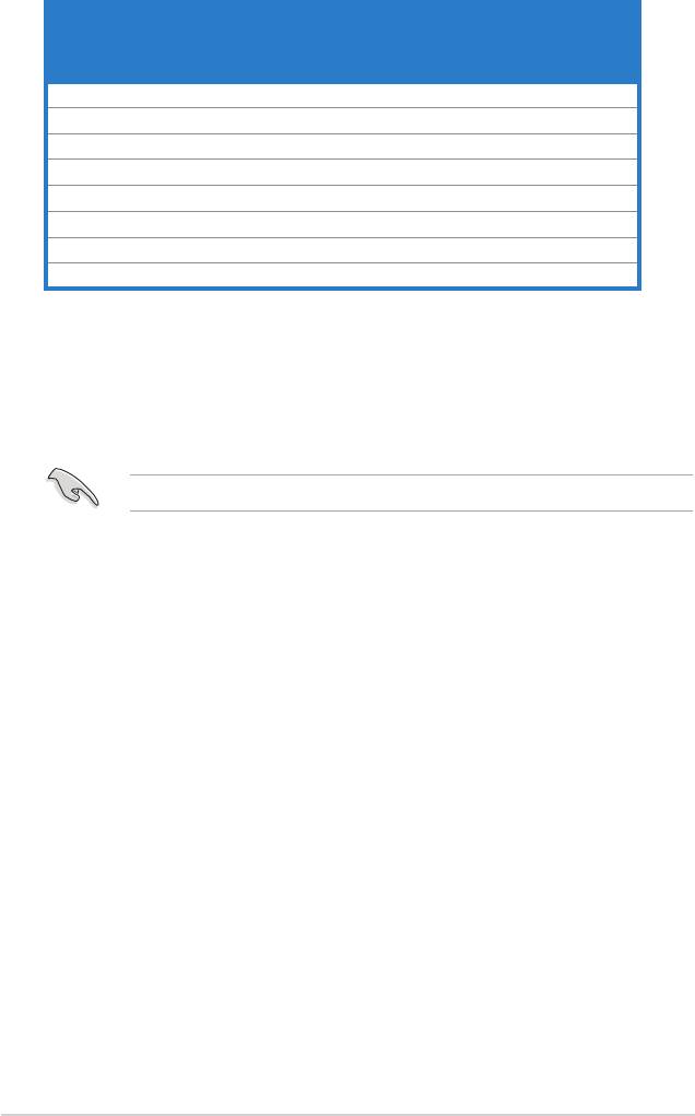
2.5.3 Interrupt assignments
Standard interrupt assignments
IRQ Priority Standard function
0 1 System Timer
1 2 Keyboard Controller
2 - Redirect to IRQ#9
5 13 IRQ Holder for PCI Steering*
6 14 Floppy Disk Controller
7 15 Nvidia nForce PCI system
8 3 System CMOS/Real Time Clock
9 4 Nvidia nForce Networking Controller
10 5 IRQ Holder for PCI Steering*
11 6 IRQ Holder for PCI Steering*
12 7 PS/2 Compatible Mouse Port*
13 8 Numeric Data Processor
14 9 Primary IDE Channel
* These IRQs are usually available for ISA or PCI devices.
IRQ assignments for this motherboard
A B C D E F G H
PCI Slot 1
shared
- - - - - - -
PCI Slot 2 -
shared
- - - - - -
PCI Slot 3
shared
Onboard 1394
shared
- - - - - - -
PCIE x 16 1
shared
- - - - - - -
PCIE x 16 2 - - - - -
shared
- -
PCIE x 4 - - - - - -
shared
-
ASUS Crosshair
2-21
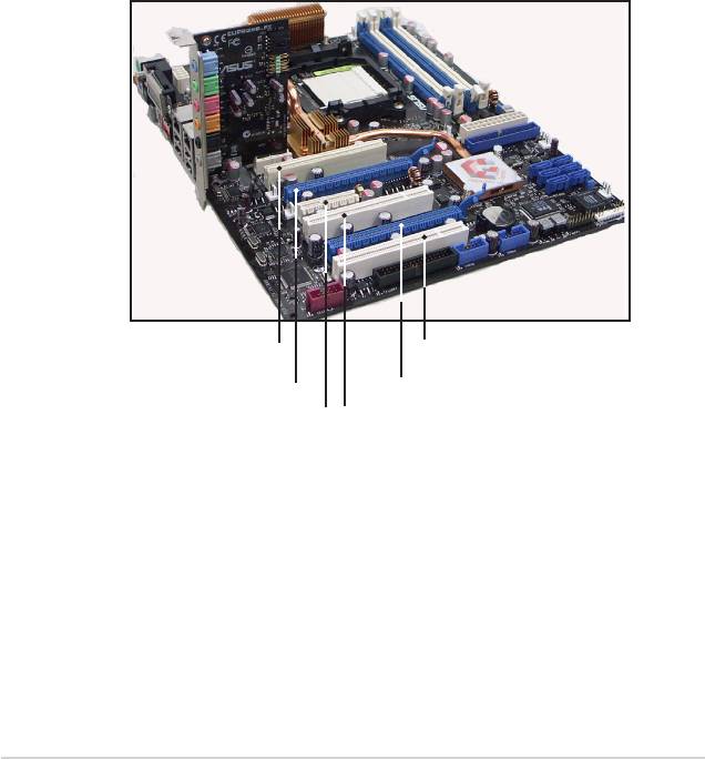
2.5.4 PCI slots
The PCI slots support cards such as a LAN card, SCSI card, USB card, and other
cards that comply with PCI specications. Refer to the gure below for the location
of the slots.
2.5.5 PCI Express x4 slot
This motherboard supports PCI Express x4 network cards, SCSI cards and other
cards that comply with the PCI Express specications. Refer to the gure below for
the location of the slot.
2.5.6 PCI Express x16 slots
This motherboard supports PCI Express x16 graphics cards that comply with the
PCI Express specications. Refer to the gure below for the location of the slots.
PCI slot
PCI slot
PCI Express x 16 slot
PCI Express x 16 slot
PCI Express x4 slot
PCI slot
2-22
Chapter 2: Hardware information
2.6 Jumper
Clear RTC RAM (CLRTC)
This jumper allows you to enable the CLRTC switch. You can clear the
CMOS memory of date, time, and system setup parameters by erasing the
CMOS RTC RAM data. The onboard clr CMOS switch helps you easily to
clear the system setup information such as system passwords. See page
2-35 for details.
To erase the RTC RAM:
1. Turn OFF the computer and unplug the power cord.
2. Move the jumper cap from pins 1-2 (default) to pins 2-3 to enable the
CLRTC function.
3. Press down the clr CMOS button and again to release it.
4. Plug the power cord and turn ON the computer.
5. Hold down the <Del> key during the boot process and enter BIOS setup
to re-enter data.
The clr CMOS button will not function until the jumper cap on CLRTC is moved
to the ENABLE position. Removing the cap will cause system boot failure!
• Make sure to re-enter your previous BIOS settings after you clear the
CMOS.
• You do not need to clear the RTC when the system hangs due to
overclocking. For system failure due to overclocking, use the C.P.R. (CPU
Parameter Recall) feature. Shut down and reboot the system so the BIOS
can automatically reset parameter settings to default values.
• To prevent accidental pressing of the Clear CMOS switch, the CLRTC
jumper default setting disables the switch.
ASUS Crosshair
2-23
CLRTC_EN
3
2
2
1
CROSSHAIR
Disable
Enable
(Default)
CROSSHAIR Clear RTC RAM
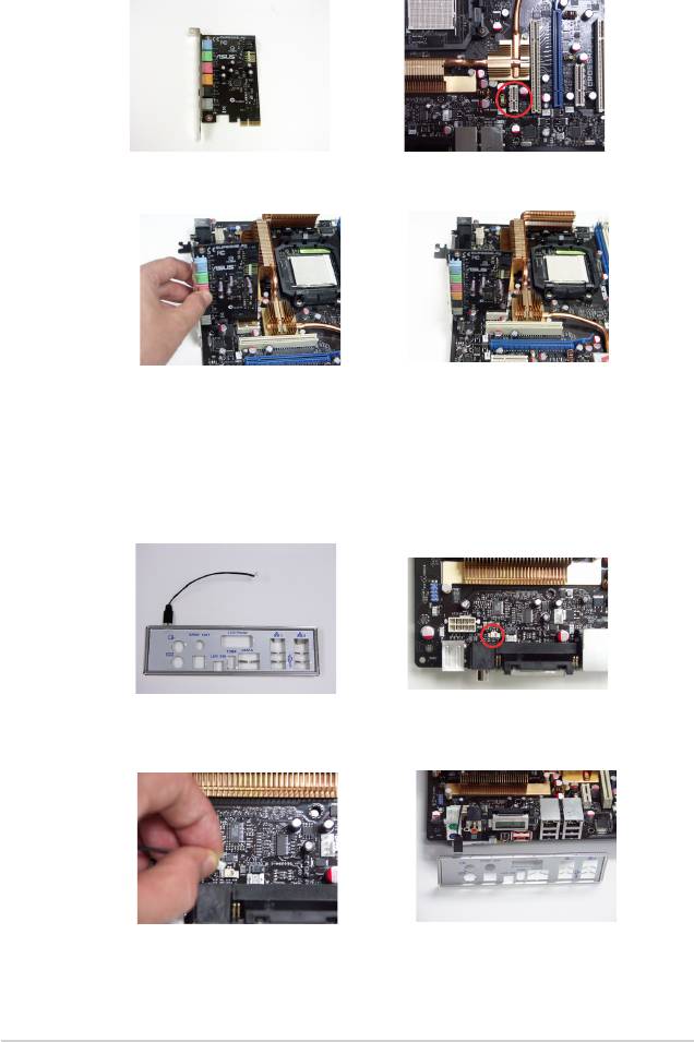
2.7 Audio Card and EL I/O Installation
2.7.1 Audio Card Installation
1. Take out the Audio card from
2. Locate the slot on the
the package.
motherboard.
3. Align the card connector
4. The above photo shows the
with the slot and press rmly
audio card installed on the
until the card sits on the slot
motherboard.
completely.
2.7.2 EL I/O Installation
1. Take out the EL I/O from the
2. Locate the connector on the
package.
motherboard.
3. Connector the cable to
4. The above photo shows
the connector in a correct
the EL I/O installed on the
orientation.
motherboard.
2-24
Chapter 2: Hardware information
2.8 Connectors
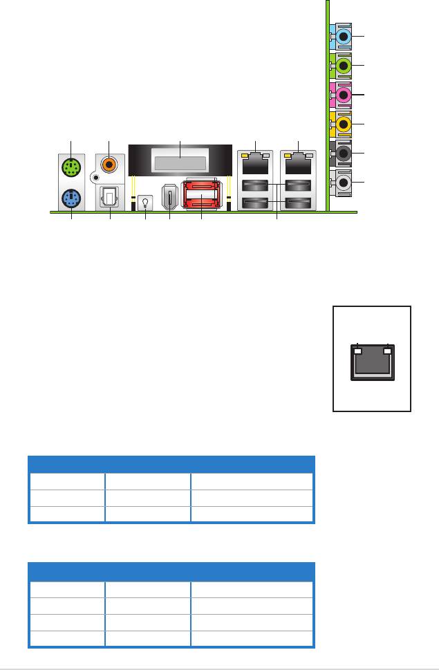
2.8.1 Rear panel connectors
1. PS/2 mouse port (green). This port is for a PS/2 mouse.
2. Coaxial S/PDIF Out port. This port connects an external audio output device
via an optical S/PDIF cable.
3. LCD Poster. This poster displays actual boot error messages.
ASUS Crosshair
2-25
6
7
8
9
1
2 3 4 5
10
11
17
16
12131415
4. LAN 1 (RJ-45) port. Supported by NV Gigabit LAN
controller, this port allows Gigabit connection to a Local
Area Network (LAN) through a network hub. Refer to the
table on the next page for the LAN port LED indications.
5. LAN 2 (RJ-45) port. Supported by the NV Gigabit LAN
controller, this port allows Gigabit connection to a Local
Area Network (LAN) through a network hub. Refer to the
table below for the LAN port LED indications.
ACTIVITY/
SPEED
LINK LED
LED
LAN port
32-bit OS LAN port LED indications
Activity/Link Speed LED Description
OFF OFF Soft-off Mode
YELLOW* OFF During Power ON/OFF
YELLOW* ORANGE 100 Mbps connection
* Blinking
64-bit OS LAN port LED indications
Activity/Link Speed LED Description
DNR DNR Soft-off Mode
DNR DNR During Power ON/OFF
DNR DNR 100 Mbps connection
DNR DNR 1 Gbps connection
6. Line In port (light blue). This port connects the tape, CD, DVD player, or
other audio sources.
7. Line Out port (lime). This port connects a headphone or a speaker. In
4-channel, 6-channel, and 8-channel conguration, the function of this port
becomes Front Speaker Out.
8. Microphone port (pink). This port connects a microphone.
9. Center/Subwoofer port (orange). This port connects the center/subwoofer
speakers.
10. Rear Speaker Out port (black). This port connects the rear speakers on a
4-channel, 6-channel, or 8-channel audio conguration.
11. Side Speaker Out port (gray). This port connects the side speakers in an
8-channel audio conguration.
Refer to the audio conguration table below for the function of the audio ports in
2, 4, 6, or 8-channel conguration.
Audio 2, 4, 6, or 8-channel conguration
Headset
Port
4-channel 6-channel 8-channel
2-channel
Light Blue Line In Line In Line In Line In
Lime Line Out Front Speaker Out Front Speaker Out Front Speaker Out
Pink Mic In Mic In Mic In Mic In
Orange – – Center/Subwoofer Center/Subwoofer
Black – Rear Speaker Out Rear Speaker Ou Rear Speaker Out
Gray – – Side Speaker Out
–
12. USB 2.0 ports 1 and 2, 3 and 4. These 4-pin Universal Serial Bus (USB)
ports are available for connecting USB 2.0 devices.
13. External SATA ports. These ports connect to an external SATA box or a
Serial ATA port multiplier. These ports support a Serial ATA hard disk drives
that you can combine with an external Serial ATA 3.0 Gb/s device to congure
a RAID 0, RAID 1, RAID 0+1 (10), RAID 5, or JBOD set through the onboard
Silicon Image® SATA RAID controller. Refer to Chapter 5 for details on how
to set up Serial ATA RAID congurations.
2-26
Chapter 2: Hardware information
• Before creating a RAID set using Serial ATA hard disks, make sure that you
have connected the Serial ATA signal cable and installed Serial ATA hard
disk drives; otherwise, you cannot enter the Silicon Image RAID utility and
SATA BIOS setup during POST.
• The external SATA ports support external Serial ATA 1.5 and 3 Gb/s
devices. Longer cables support higher power requirements to deliver signal
up to two meters away, and enables improved hot-swap function.
• If you intend to create a RAID conguration using this connector, set the
Silicon 3132 Controller item in the BIOS to [RAID Mode]. See section “4.4.6
Onboard Devices Conguration” for details.
• Use these ports and an external Serial ATA box connected to the external
SATA port, if you want to congure a RAID 0 or RAID 1 set.
• The Serial ATA port multiplier and external Serial ATA box are purchased
separately.
• DO NOT insert a different connector to this port.
• DO NOT unplug the external Serial ATA box when a RAID 0 or RAID 1 is
congured.
14. IEEE 1394a port. This 6-pin IEEE 1394a port provides high-speed
connectivity for audio/video devices, storage peripherals, PCs, or portable
devices.
15. Onboard LED switch. This motherboard features onboard LEDs that light
up the labels, making it easy for you to install or plug in devices even in the
dark. Press this switch to turn on the onboard LEDs.
16. Optical S/PDIF Out port. This port connects an external audio output device
via an optical S/PDIF cable.
17. PS/2 keyboard port (purple). This port is for a PS/2 keyboard.
ASUS Crosshair
2-27
2.8.2 Internal connectors
1. Floppy disk drive connector (34-1 pin FLOPPY)
This connector is for the provided oppy disk drive (FDD) signal cable. Insert
one end of the cable to this connector, then connect the other end to the
signal connector at the back of the oppy disk drive.
Pin 5 on the connector is removed to prevent incorrect cable connection when
using a FDD cable with a covered Pin 5.
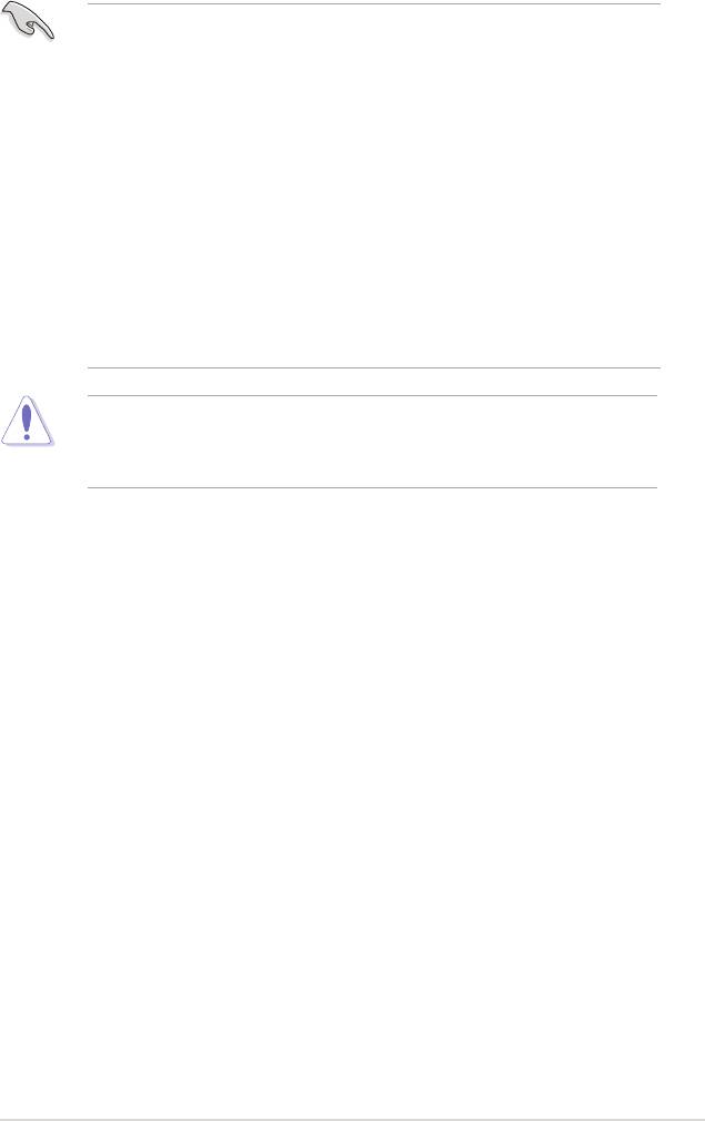
2. IDE connector (40-1 pin PRI_IDE)
The onboard IDE connector is for the Ultra DMA (133/)100/66 signal cable.
There are three connectors on each Ultra DMA 133/100/66 signal cable:
blue, black, and gray. Connect the blue connector to the motherboard’s IDE
connector, then select one of the following modes to congure your device.
2-28
Chapter 2: Hardware information
FLOPPY
NOTE: Orient the red markings on
the floppy ribbon cable to PIN1.
CROSSHAIR
PIN1
CROSSHAIR Floppy disk drive connector
Mode of
Drive jumper setting
Cable connector
device(s)
Single device Cable-Select or Master - Black
Black
Master
Cable-Select
Slave Gray
Two devices
Master Master
Black or gray
Slave Slave
• Pin 20 on the IDE connector is removed to match the covered hole on the
Ultra DMA cable connector. This prevents incorrect insertion when you
connect the IDE cable.
• Use the 80-conductor IDE cable for Ultra DMA 133/100/66 IDE devices.
If any device jumper is set as “Cable-Select,” make sure all other device
jumpers have the same setting.
ASUS Crosshair
2-29
PRI_IDE
NOTE: Orient the red markings
(usually zigzag) on the IDE
ribbon cable to PIN1.
PIN1
CROSSHAIR
CROSSHAIR IDE connector
®
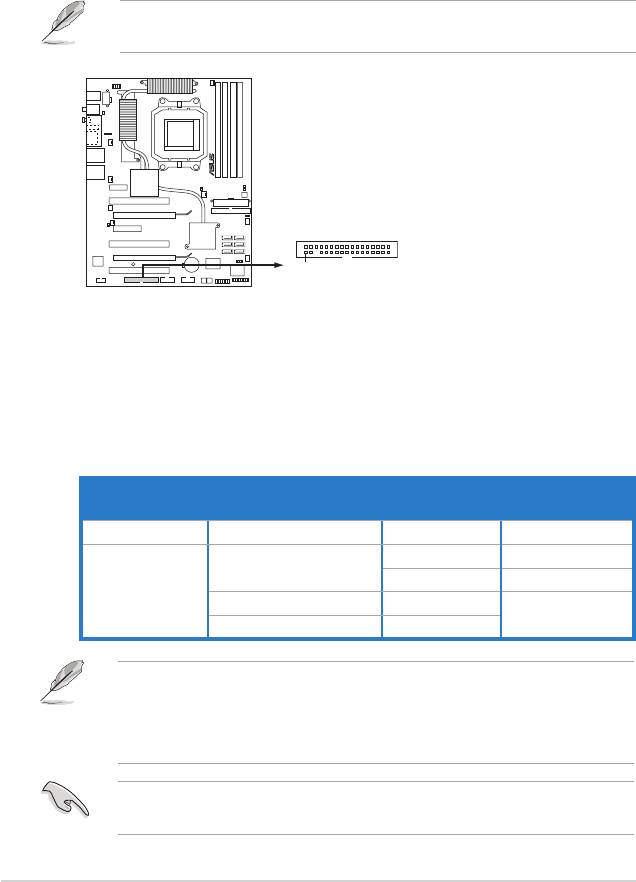
3. NVIDIA
NF590-SLI Southbridge Serial ATA connectors (7-pin SATA1
[blue], SATA2 [blue], SATA3 [blue], SATA4 [blue], SATA5 [blue], SATA6
[blue])
These connectors are for the Serial ATA signal cables for Serial ATA 3.0
Gb/s hard disk and optical disk drives. The Serial ATA 3.0 Gb/s is backward
compatible with Serial ATA 1.5 Gb/s specication.
If you installed Serial ATA hard disk drives, you can create a RAID 0, RAID 1,
RAID 0+1 (10), RAID 5, or JBOD conguration through the onboard NVRAID
®
controller. Refer to section “5.4.1 NVIDIA
RAID congurations” for details on
how to set up Serial ATA RAID congurations.
The RAID function of these connectors is set to [Disabled] by default. If you
intend to create a Serial ATA RAID set using these connectors, enable the RAID
Enabled item in the BIOS. See section “4.5.4 Onboard Device Conguration >
Serial-ATA Conguration” for details.
SATA5
SATA6
GND
GND
GND
GND
GND
GND
RSATA_TX_5_DP
RSATA_TX_5_DN
RSATA_RX_5_DN
RSATA_RX_5_DP
RSATA_TX_6_DP
RSATA_TX_6_DN
RSATA_RX_6_DN
RSATA_RX_6_DP
SATA3
SATA4
GND
GND
GND
GND
GND
GND
RSATA_TX_3_DP
RSATA_TX_3_DN
RSATA_RX_3_DN
RSATA_RX_3_DP
RSATA_TX_4_DP
RSATA_TX_4_DN
RSATA_RX_4_DN
RSATA_RX_4_DP
CROSSHAIR
SATA1
SATA2
GND
GND
GND
GND
GND
GND
RSATA_TX_1_DP
RSATA_TX_1_DN
RSATA_RX_1_DN
RSATA_RX_1_DP
RSATA_TX_2_DP
RSATA_TX_2_DN
RSATA_RX_2_DN
RSATA_RX_2_DP
CROSSHAIR SATA connectors
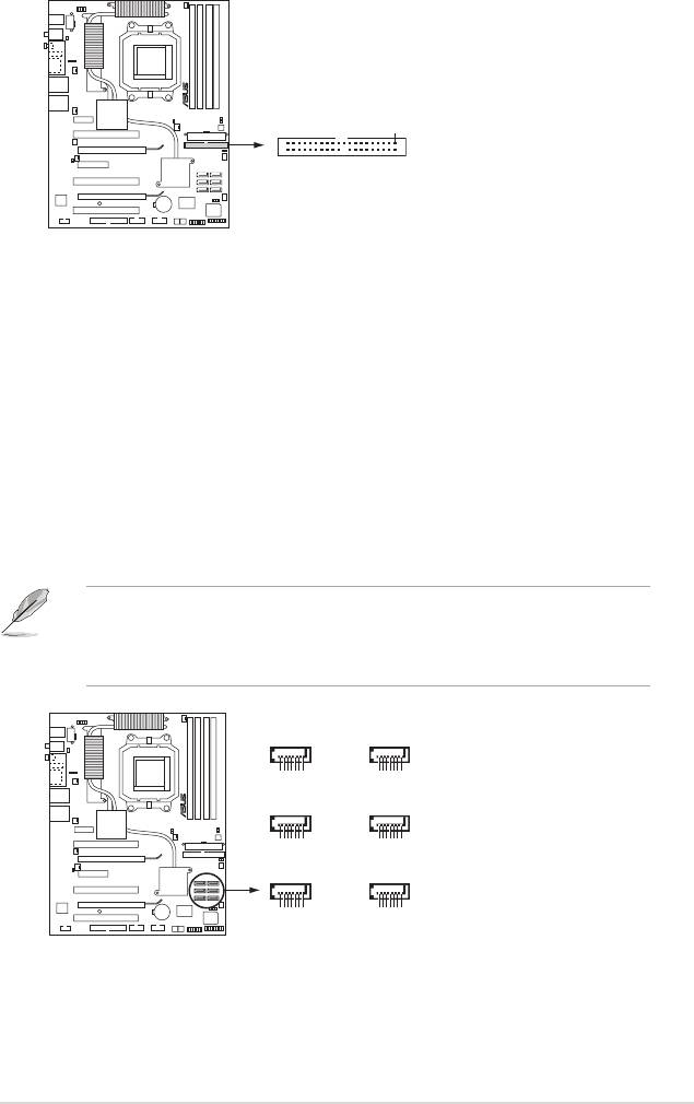
4. USB connectors (10-1 pin USB56, USB78, USB910)
These connectors are for USB 2.0 ports. Connect the USB/GAME module
cable to any of these connectors, then install the module to a slot opening at
the back of the system chassis. These USB connectors comply with USB 2.0
specication that supports up to 480 Mbps connection speed.
Never connect a 1394 cable to the USB connectors. Doing so will damage the
motherboard!
2-30
Chapter 2: Hardware information
USB+5V
USB_P10-
USB_P10+
GND
NC
USB910
GND
USB+5V
USB_P9-
USB_P9+
CROSSHAIR
GND
USB_P5+
USB_P5-
USB+5V
GND
USB_P7+
USB_P7-
USB+5V
USB56 USB78
NC
NC
GND
GND
CROSSHAIR USB 2.0 connectors
USB_P6+
USB_P6-
USB+5V
USB_P8+
USB_P8-
USB+5V
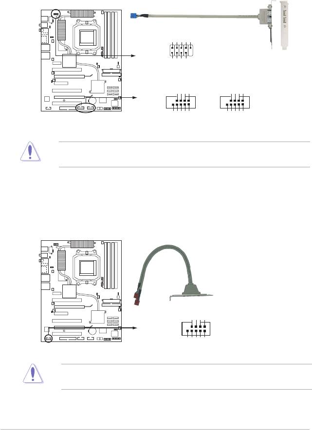
5. IEEE 1394a port connector (10-1 pin IE1394_2)
This connector is for a IEEE 1394a port. Connect the IEEE 1394a module
cable to this connector, then install the module to a slot opening at the back
of the system chassis.
Never connect a USB cable to the IEEE 1394a connector. Doing so will damage
the motherboard!
CROSSHAIR
+12V
TPB2-+
GND
TPA2-+
1
IE1394_2
GND
+12V
GND
TPB2-
TPA2-
CROSSHAIR IEEE 1394 connector
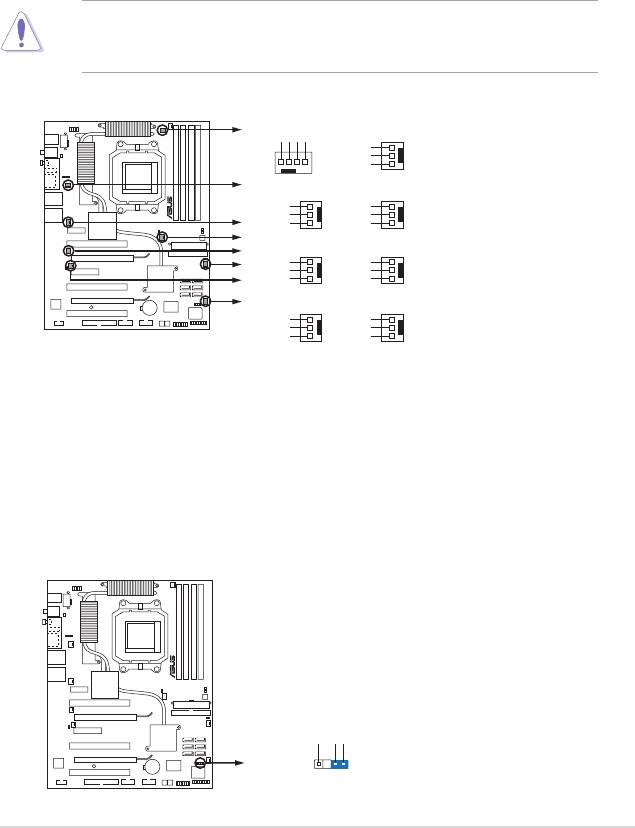
6. CPU, chassis, and optional fan connectors
(4-pin CPU_FAN, 3-pin CHA_REAR_FAN, 3-pin CHA_FRONT_FAN, 3-pin
OPT_FAN1, 3-pin OPT_FAN2, 3-pin OPT_FAN3, 3-pin OPT_FAN4, 3-pin
OPT_FAN5)
The fan connectors support cooling fans of 350 mA ~ 1000 mA (24 W max.) or
a total of 1 A ~ 3.48 A (41.76 W max.) at +12V. Connect the fan cables to the
fan connectors on the motherboard, making sure that the black wire of each
cable matches the ground pin of the connector.
Do not forget to connect the fan cables to the fan connectors. Insufcient air
ow inside the system may damage the motherboard components. These are
not jumpers! Do not place jumper caps on the fan connectors!
ASUS Crosshair 2-31
CPU_FAN
OPT_FAN5
OPT_FAN4
GND
+12V
Rotation
RPM adjustment
Rotation
+12V
GND
CPU_FAN
OPT_FAN1
OPT_FAN5
Rotation
Rotation
OPT_FAN4
+12V
+12V
GND
GND
OPT_FAN3
CHA__REAR_FAN
OPT_FAN2
CHA_FRONT_FAN
OPT_FAN1
Rotation
Rotation
+12V
+12V
OPT_FAN2
CROSSHAIR
GND
GND
CHA__FRONT_FAN
OPT_FAN3
CHA_REAR_FAN
Rotation
Rotation
+12V
+12V
GND
GND
CROSSHAIR Fan connectors
7. Chassis intrusion connector (4-1 pin CHASSIS)
This connector is for a chassis-mounted intrusion detection sensor or switch.
Connect one end of the chassis intrusion sensor or switch cable to this
connector. The chassis intrusion sensor or switch sends a high-level signal to
this connector when a chassis component is removed or replaced. The signal
is then generated as a chassis intrusion event.
By default, the pins labeled “Chassis Signal” and “Ground” are shorted with
a jumper cap. Remove the jumper caps only when you intend to use the
chassis intrusion detection feature.
CROSSHAIR
+5VSB_MB
Chassis Signal
GND
CHASSIS
(Default)
CROSSHAIR Chassis intrusion connector
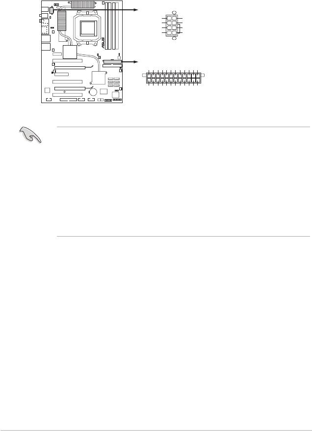
8. ATX power connectors
(24-pin EATXPWR, 8-pin EATX12V)
These connectors are for ATX power supply plugs. The power supply plugs
are designed to t these connectors in only one orientation. Find the proper
orientation and push down rmly until the connectors completely t.
2-32 Chapter 2: Hardware information
ATX12V
GND
+12V DC
GND
+12V DC
GND
+12V DC
GND
+12V DC
EATXPWR
Ground
+5 Volts
+5 Volts
+5 Volts
-5 Volts
Ground
Ground
Ground
PSON#
Ground
-12 Volts
+3 Volts
CROSSHAIR
+3 Volts
+12 Volts
+12 Volts
+5V Standby
Power OK
Ground
+5 Volts
Ground
+5 Volts
Ground
+3 Volts
+3 Volts
CROSSHAIR ATX power connectors
•
For a fully congured system, we recommend that you use a power supply
unit (PSU) that complies with ATX 12 V Specication 2.0 (or later version)
and provides a minimum power of 600 W.
• Do not forget to connect the 8-pin ATX +12 V power plug; otherwise, the
system will not boot.
®
• To support an AMD
Dual-Core CPU,make sure that the PSU can provide
at least 16 A and 19 A peak on the +12V_2 lead.
• Use of a PSU with a higher power output is recommended when conguring
a system with more power-consuming devices. The system may become
unstable or may not boot up if the power is inadequate.
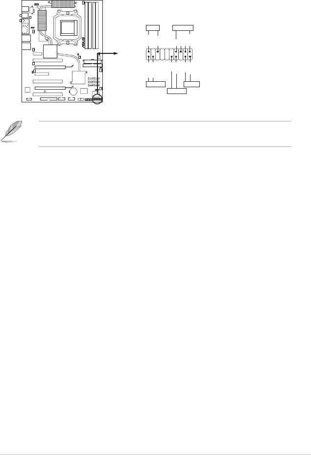
14. System panel connector (20-pin PANEL)
This connector supports several chassis-mounted functions.
The sytem panel connector is color-coded for easy connection. Refer to the
connector descriptions on the next page for details.
•
System power LED (3-pin PLED)
This 3-pin connector is for the system power LED. Connect the chassis
power LED cable to this connector. The system power LED lights up when
you turn on the system power, and blinks when the system is in sleep mode.
•
Hard disk drive activity LED (2-pin IDE_LED)
This 2-pin connector is for the HDD Activity LED. Connect the HDD Activity
LED cable to this connector. The IDE LED lights up or ashes when data is
read from or written to the HDD.
•
System warning speaker (4-pin SPEAKER)
This 4-pin connector is for the chassis-mounted system warning speaker. The
speaker allows you to hear system beeps and warnings.
•
ATX power button/soft-off button (2-pin PWR)
This connector is for the system power button. Pressing the power button
turns the system on or puts the system in sleep or soft-off mode depending
on the BIOS settings. Pressing the power switch for more than four seconds
while the system is ON turns the system OFF.
•
Reset button (2-pin RESET)
This 2-pin connector is for the chassis-mounted reset button for system
reboot without turning off the system power.
ASUS Crosshair 2-33
PLED
SPEAKER
PLED+
PLED-
+5V
Ground
Ground
Speaker
PANEL
PWR
Reset
Ground
Ground
IDE_LED+
IDE_LED-
CROSSHAIR
IDE_LED
RESET
PWRSW
* Requires an ATX power supply
CROSSHAIR System panel connector
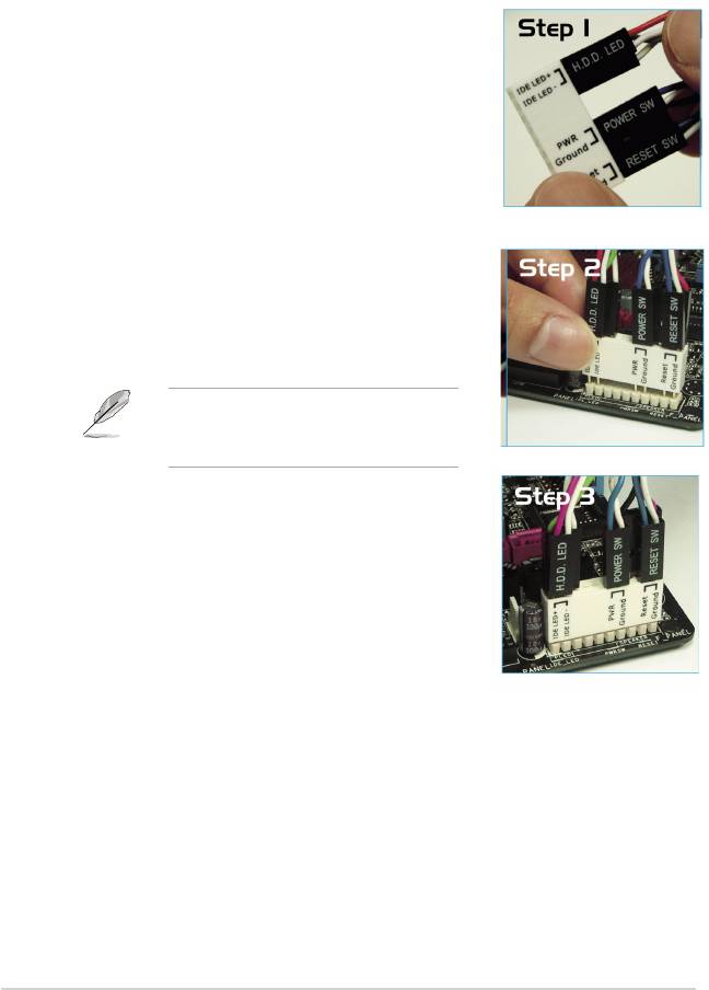
Q-Connector (System panel)
ASUS Q-Connector allows you to easily to connect the chassis front panel cables
to the motherboard. Perform these steps to install ASUS Q-Connector.
Step1.
Connect the front panel cables to their
respective connectors on the ASUS Q-
Connector. Refer to the labels on the
Q-Connector for proper connection and pin
denition.
Step2.
Carefully connect the ASUS
Q-Connector to the System panel
connector.
The ASUS Q-Connector ts only in one
orientation; if it doesn’t t, try reversing
it.
Step3.
When installed, the Q-connector appears
as shown.
2-34 Chapter 2: Hardware information
2.8.3 Onboard switches
Onboard switches allow you to ne-tune performance when working on a bare
or open-case system. This is ideal for overclockers and gamers who continually
change settings to enhance system performance.
1. Clear CMOS switch
Press the clear CMOS switch to clear setup information when the system
hangs due to overclocking.
ASUS Crosshair 2-35
CROSSHAIR
CROSSHAIR CMOS switch
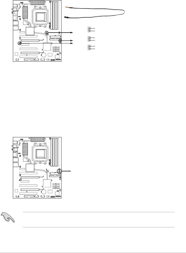
15. Thermal sensor cable connectors (W1/2/3, 2-pin)
These connectors are for temperature monitoring. Connect the thermal
sensor cables to these connectors and place the other ends to the devices,
which you want to monitor temperature. The optional fan1~3 can work with
the temperature sensors for a better cooling effect.
To prevent accidental pressing of the Clear CMOS switch, the CLRTC jumper
default setting disables the switch. See page 2-23 for details.
WJ1
Temperature2
Ground
WJ2
Temperature2
Ground
CROSSHAIR
WJ3
Temperature3
Ground
CROSSHAIR Thermal sensor cable connectors
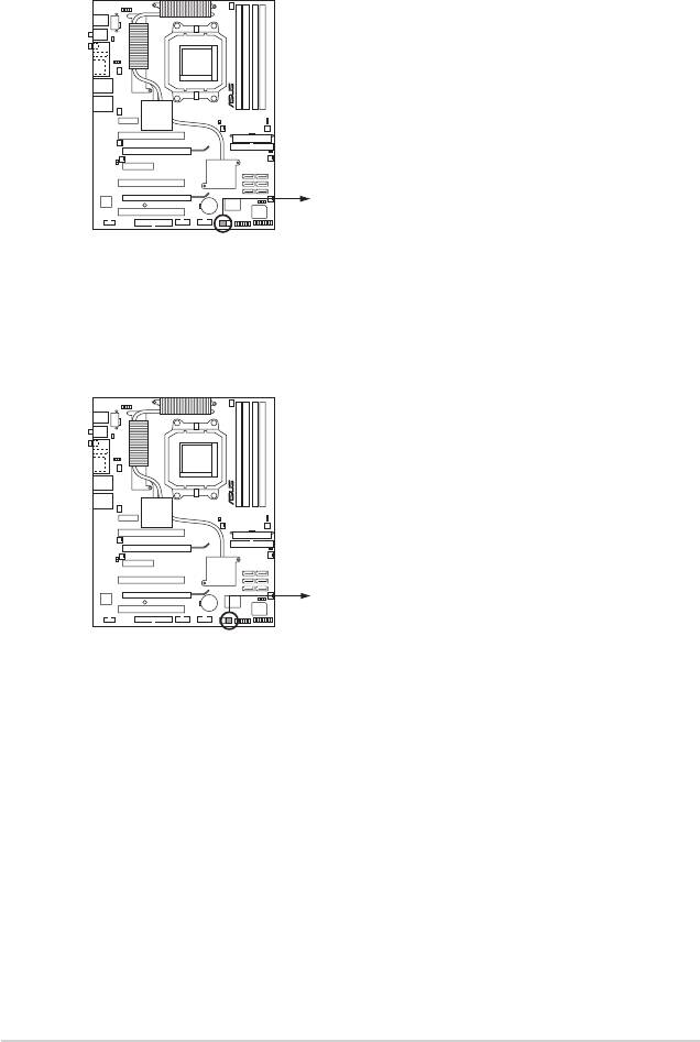
2. Power-on switch
Press the clear power-on switch to wake/power up the system.
2-36 Chapter 2: Hardware information
CROSSHAIR
CROSSHAIR Power on switch
3. Reset switch
Press the reset switch to reboot the system.
CROSSHAIR
CROSSHAIR Reset switch
