Pioneer DEH-X8500DAB: Power amp (sold separately) When installing the microphone on the sun visor When installing the microphone on the steering column
Power amp (sold separately) When installing the microphone on the sun visor When installing the microphone on the steering column: Pioneer DEH-X8500DAB
Table of contents
- Removing the unit DIN front/rear mount
- Power cord This unit
- Power amp (sold separately) When installing the microphone on the sun visor When installing the microphone on the steering column
- Adjusting the microphone angle
a Blue/white
! Only for DEH-X8500DAB and DEH-X8500BT
Power amp (sold separately)
The pin position of the ISO connector will dif-
Perform these connections when using the op-
fer depending on the type of vehicle. Connect
tional amplifier.
CAUTION
a and b when Pin 5 is an antenna control
It is extremely dangerous to allow the micro-
1
type. In another type of vehicle, never con-
1
3
phone lead to become wound around the steer-
nect a and b.
2
ing column or shift lever. Be sure to install the
b Blue/white
4
unit in such a way that it will not obstruct driv-
Connect to system control terminal of the
55
ing.
power amp (max. 300 mA 12 V DC).
3
c Blue/white
Note
Connect to auto-antenna relay control termi-
1
2
6
Install the microphone in a position and orienta-
nal (max. 300 mA 12 V DC).
77
tion that will enable it to pick up the voice of the
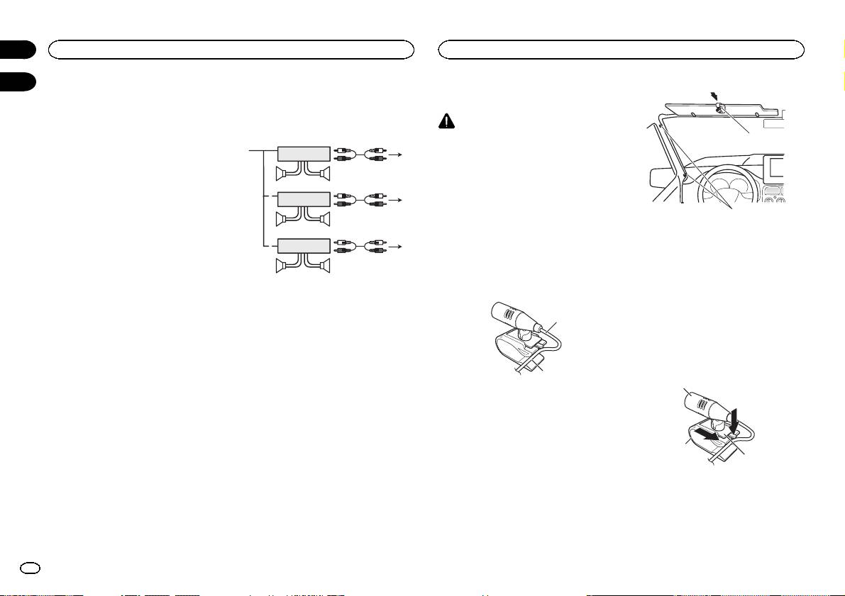
d Speaker leads
person operating the system.
White: Front left +
3
White/black: Front left *
2
Gray: Front right +
1
8
When installing the
Gray/black: Front right *
99
microphone on the sun visor
Green: Rear left + or subwoofer +
Green/black: Rear left * or subwoofer *
1 Fit the microphone lead into the groove.
1 System remote control
Violet: Rear right + or subwoofer +
Connect to Blue/white cable.
Violet/black: Rear right * or subwoofer *
2 Power amp (sold separately)
e ISO connector
1
3 Connect with RCA cable (sold separately)
In some vehicles, the ISO connector may be
4 To Rear output
divided into two. In this case, be sure to con-
5 Rear speaker
nect to both connectors.
6 To Front output
Notes
7 Front speaker
2
8 To subwoofer output
! Change the set up menu of this unit (refer to
9 Subwoofer
the operation manual). The subwoofer output
1 Microphone lead
of this unit is monaural.
2 Groove
! When using a subwoofer of 70 W (2 W), be
sure to connect the subwoofer to the violet
2 Install the microphone clip on the sun
and violet/black leads of this unit. Do not
visor.
connect anything to the green and green/
With the sun visor up, install the microphone
black leads.
clip. (Lowering the sun visor reduces the voice
recognition rate.)
2
Section
02
Connections
Installing the microphone
03
1 Microphone clip
2 Clamp
Use separately sold clamps to secure the
lead where necessary inside the vehicle.
When installing the
microphone on the steering
column
1 Detach the microphone base from the mi-
crophone clip.
To detach the microphone base from the micro-
phone clip, slide the microphone base.
1
2
3
1 Microphone
2 Microphone clip
3 Microphone base
4
En
