Dell PowerEdge 1950 – страница 6
Инструкция к Компьютеру Dell PowerEdge 1950
Оглавление
The power supply's fault indicator is lit. See "Power Indicator Codes" on page 15.
NOTICE: You can hot-plug the power supplies. One power supply must be installed for the system to operate.
The system is in the redundant mode when two power supplies are installed. Remove and install only one power
supply at a time in a system that is powered on. Operating the system for extended periods of time with only one
power supply installed, without a power supply blank installed, can cause the system to overheat.
Remove the faulty power supply. See "Power Supplies" on page 53.
3
Ensure that the power supply is properly installed by removing and reinstalling it. See "Power Supplies"
on page 53.
NOTE: After installing a power supply, allow several seconds for the system to recognize the power supply
and to determine if it is working properly. The power indicator turns green to signify that the power supply is
functioning properly. See "Power Indicator Codes" on page 15.
If the problem persists, see "Getting Help" on page 125.
Troubleshooting System Cooling Problems
Problem
• Systems management software issues a fan-related error message.
Action
Ensure that none of the following conditions exist:
• Ambient temperature is too high.
• External airflow is obstructed.
• Cables inside the system obstruct airflow.
• An individual cooling fan has failed. See "Troubleshooting a Fan" on page 101.
Troubleshooting a Fan
Problem
• System-status indicator is amber.
• Systems management software issues a fan-related error message.
• Display module LCD indicates a problem with the fan.
Action
CAUTION: Many repairs may only be done by a certified service technician. You should only perform
troubleshooting and simple repairs as authorized in your product documentation, or as directed by the online or
telephone service and support team. Damage due to servicing that is not authorized by Dell is not covered by your
warranty. Read and follow the safety instructions that came with the product.
1
Run the appropriate diagnostic test. See "Using Server Administrator Diagnostics" on page 111.
Troubleshooting Your System 101
2
Open the system. See "Opening and Closing the System" on page 46.
CAUTION: The cooling fans are not hot-pluggable. To maintain proper cooling while the system is on, only
replace one fan at a time.
3
Locate the faulty fan indicated by the LCD display or diagnostic software. For the identification number
of each fan, see "Removing and Installing a Cooling Fan" on page 49.
4
Ensure that the faulty fan's power cable is firmly attached to the fan power connector. See "Cooling Fan
Modules" on page 48.
NOTE: Wait 30 seconds for the system to recognize the fan and determine whether it is working properly.
5
If the problem is not resolved, install a new fan. See "Cooling Fan Modules" on page 48.
If the replacement fan is working properly, close the system. See "Opening and Closing the System" on
page 46.
If the replacement fan does not operate, see "Getting Help" on page 125.
Troubleshooting System Memory
Problem
• Faulty memory module.
• Faulty system board.
• Front-panel status LCD indicates a problem with system memory.
Action
CAUTION: Many repairs may only be done by a certified service technician. You should only perform
troubleshooting and simple repairs as authorized in your product documentation, or as directed by the online or
telephone service and support team. Damage due to servicing that is not authorized by Dell is not covered by your
warranty. Read and follow the safety instructions that came with the product.
1
Run the appropriate online diagnostic test. See "Using Server Administrator Diagnostics" on page 111.
2
Turn on the system and attached peripherals.
If an error message does not appear, continue to the next step.
If an error message appears, go to step 12.
3
Enter the System Setup program and check the system memory setting. See "Entering the System Setup
Program" on page 31.
If the amount of memory installed matches the system memory setting, go to step 12.
4
Turn off the system and attached peripherals, and disconnect the system from the electrical outlet.
5
Open the system. See "Opening and Closing the System" on page 46.
6
Remove the memory cooling shroud. See "Removing the Memory Cooling Shroud" on page 52.
102 Troubleshooting Your System

7
Reseat the memory modules in their sockets. See "Installing Memory Modules" on page 65.
8
Replace the memory cooling shroud. See "Replacing the Memory Cooling Shroud" on page 53.
9
Close the system. See "Opening and Closing the System" on page 46.
10
Reconnect the system to its electrical outlet, and turn on the system and attached peripherals.
11
Enter the System Setup program and check the system memory setting. See "Using the System Setup
Program" on page 31.
If the amount of memory installed does not match the system memory setting, then perform the following
steps:
a
Turn off the system and attached peripherals, and disconnect the system from its electrical outlet.
b
Open the system. See "Opening and Closing the System" on page 46.
NOTE: Several configurations for memory modules exist; see "General Memory Module Installation
Guidelines" on page 64.
c
Swap the memory module in socket 1 with another of the same capacity. See "Installing Memory
Modules" on page 65.
d
Close the system. See "Opening and Closing the System" on page 46.
e
Reconnect the system to its electrical outlet, and turn on the system and attached peripherals.
f
As the system boots, observe the monitor screen and the indicators on the keyboard.
12
Perform the following steps:
a
Turn off the system and attached peripherals, and disconnect the system from its electrical outlet.
b
Open the system. See "Opening and Closing the System" on page 46.
c
Perform step c through step f in step 11 for each memory module installed.
If the problem persists, see "Getting Help" on page 125.
Troubleshooting an Optical Drive
Problem
• System cannot read data from a CD or DVD in an optical drive.
• Optical drive indicator does not blink during boot.
NOTE: DVD devices are data only.
Action
CAUTION: Many repairs may only be done by a certified service technician. You should only perform
troubleshooting and simple repairs as authorized in your product documentation, or as directed by the online or
telephone service and support team. Damage due to servicing that is not authorized by Dell is not covered by your
warranty. Read and follow the safety instructions that came with the product.
Troubleshooting Your System 103
1
Try using a different CD or DVD that you know works properly.
2
Enter the System Setup program and ensure that the drive’s IDE controller is enabled. See "Using the
System Setup Program" on page 31.
3
Run the appropriate online diagnostic test. See "Using Server Administrator Diagnostics" on page 111.
4
Turn off the system and attached peripherals, and disconnect the system from the electrical outlet.
5
Open or remove the bezel. See "Removing and Replacing the Front Bezel" on page 45
6
Open the system. See "Opening and Closing the System" on page 46.
7
Ensure that the interface cable is securely connected to the optical drive and to the sideplane.
8
Remove the SAS controller daughter card or the SAS RAID controller daughter card, as applicable. See
"Removing a SAS Controller Daughter Card" on page 56.
9
Close the system. See "Opening and Closing the System" on page 46.
10
Reconnect the system to the electrical outlet, and turn on the system and attached peripherals.
If the problem is not resolved, see "Getting Help" on page 125.
Troubleshooting a Hard Drive
Problem
• Device driver error.
• One or more hard drives not recognized by the system.
Action
CAUTION: Many repairs may only be done by a certified service technician. You should only perform
troubleshooting and simple repairs as authorized in your product documentation, or as directed by the online or
telephone service and support team. Damage due to servicing that is not authorized by Dell is not covered by your
warranty. Read and follow the safety instructions that came with the product.
NOTICE: This troubleshooting procedure can destroy data stored on the hard drive. Before you proceed, back up
all files on the hard drive.
1
Run the appropriate online diagnostic test. See "Using Server Administrator Diagnostics" on page 111.
Depending on the results of the diagnostics test, proceed as needed through the following steps.
2
Remove the bezel. See "Removing and Replacing the Front Bezel" on page 45.
3
If you are experiencing problems with multiple hard drives, skip to step 8. For a problem with a single
hard drive, continue to the next step.
4
Turn off your system, reseat the hard drive, and restart the system.
5
If your system has a SAS RAID controller daughter card, perform the following steps.
a
Restart the system and press <Ctrl><R> to enter the host adapter configuration utility program.
104 Troubleshooting Your System

See the documentation supplied with the host adapter for information about the configuration utility.
b
Ensure that the hard drive has been configured correctly for the RAID.
c
Exit the configuration utility and allow the system to boot to the operating system.
6
Ensure that the required device drivers for your controller daughter card are installed and are configured
correctly. See the operating system documentation for more information.
NOTICE: Do not perform the following step if you have a SAS RAID controller daughter card.
7
If you have the non-RAID SAS controller daughter card, remove the hard drive and swap its drive bay
location with another hard drive that is functioning properly.
If the problem is resolved, reinstall the hard drive in the original bay. See "Installing a Hot-Plug Hard
Drive" on page 76.
If the hard drive functions properly in the original bay, the drive carrier could have intermittent problems.
Replace the hard-drive carrier.
See "Getting Help" on page 125.
If the hard drive functioned properly in another bay but does not function in the original bay, the SAS
backplane has a defective connector.
See "Getting Help" on page 125.
8
Check the cable connections inside the system:
a
Turn off the system, including any attached peripherals, and disconnect the system from the electrical
outlet.
b
Open the system. See "Opening and Closing the System" on page 46.
c
Verify that the cable connections between SAS backplane(s) and the SAS daughter card are correct.
See "Installing a SAS Controller Daughter Card or SAS RAID Controller Daughter Card" on page 56.
d
Verify that the SAS cables are securely seated in their connectors.
e
Verify that the power connectors on the SAS backplane(s) are securely seated in their connectors.
f
Close the system. See "Opening and Closing the System" on page 46.
g
Reconnect the system to the electrical outlet, and turn on the system and attached peripherals.
If the problem persists,
see "Getting Help" on page 125.
Troubleshooting a SAS or SAS RAID Controller Daughter Card
NOTE: When troubleshooting a SAS or SAS RAID controller daughter card, also see the documentation for your
operating system and the controller daughter card.
Problem
• Error message indicates a problem with the SAS or SAS RAID controller daughter card.
• SAS or SAS RAID controller daughter card performs incorrectly or not at all.
Troubleshooting Your System 105

Action
CAUTION: Many repairs may only be done by a certified service technician. You should only perform
troubleshooting and simple repairs as authorized in your product documentation, or as directed by the online or
telephone service and support team. Damage due to servicing that is not authorized by Dell is not covered by your
warranty. Read and follow the safety instructions that came with the product.
1
Run the appropriate online diagnostic test. See "Using Server Administrator Diagnostics" on page 111.
2
Enter the System Setup program and ensure that the SAS or SAS RAID controller daughter card is
enabled. See "Using the System Setup Program" on page 31.
3
Restart the system and press the applicable key sequence to enter the configuration utility program:
• <Ctrl><C> for a SAS controller
• <Ctrl><R> for a SAS RAID controller
See the controller's documentation for information about configuration settings.
4
Check the configuration settings, make any necessary corrections, and restart the system.
If the problem is not resolved, continue to the next step.
5
Remove the bezel. See "Removing and Replacing the Front Bezel" on page 45.
6
Turn off the system and attached peripherals, and disconnect the system from its electrical outlet.
7
Open the system. See "Opening and Closing the System" on page 46.
8
Ensure that the controller card is firmly seated in its connector. See "SAS Controller Daughter Card" on
page 56.
9
If you have a SAS RAID controller daughter card, ensure that the following RAID components are
properly installed and connected:
• Memory module
• Battery
10
Verify that the cable connections between the SAS backplane(s) and the SAS controller daughter card are
correct. See "Installing a SAS Controller Daughter Card or SAS RAID Controller Daughter Card" on
page 56.
11
Ensure that the cables are firmly connected to the SAS controller daughter card and the SAS backplane
board.
12
Close the system. See "Opening and Closing the System" on page 46.
13
Reconnect the system to its electrical outlet, and turn on the system and attached peripherals. If the
problem persists, proceed as follows:
• If you have a SAS controller daughter card,
see "Getting Help" on page 125.
• If you have a SAS RAID controller daughter card, replace the SAS RAID daughter card battery
.
See
"Installing a RAID Battery" on page 60. If replacing the battery does not solve the problem,
see
"Getting Help" on page 125.
106 Troubleshooting Your System

Troubleshooting Expansion Cards
NOTE: When troubleshooting an expansion card, see the documentation for your operating system and the
expansion card.
Problem
• Error message indicates a problem with an expansion card.
• Expansion card performs incorrectly or not at all.
Action
CAUTION: Many repairs may only be done by a certified service technician. You should only perform
troubleshooting and simple repairs as authorized in your product documentation, or as directed by the online or
telephone service and support team. Damage due to servicing that is not authorized by Dell is not covered by your
warranty. Read and follow the safety instructions that came with the product.
1
Run the appropriate online diagnostic test. See "Using Server Administrator Diagnostics" on page 111.
2
Open or remove the bezel. See "Removing and Replacing the Front Bezel" on page 45.
3
Turn off the system and attached peripherals, and disconnect the system from the electrical outlet.
4
Open the system. See "Opening and Closing the System" on page 46.
5
Ensure that each expansion card is firmly seated in its connector. See "Installing an Expansion Card" on
page 61.
6
Close the system. See "Opening and Closing the System" on page 46.
7
Reconnect the system to the electrical outlet, and turn on the system and attached peripherals.
If the problem persists, go to the next step.
8
Turn off the system and attached peripherals, and disconnect the system from the electrical outlet.
9
Open the system. See "Opening and Closing the System" on page 46.
10
Remove all expansion cards installed in the system. See "Installing an Expansion Card" on page 61.
11
Close the system. See "Opening and Closing the System" on page 46.
12
Reconnect the system to the electrical outlet, and turn on the system and attached peripherals.
13
Run the appropriate online diagnostic test.
If the tests fail,
see "Getting Help" on page 125.
14
For each expansion card you removed in step 10, perform the following steps:
a
Turn off the system and attached peripherals, and disconnect the system from the electrical outlet.
b
Open the system. See "Opening and Closing the System" on page 46.
c
Reinstall one of the expansion cards.
Troubleshooting Your System 107

d
Close the system. See "Opening and Closing the System" on page 46.
e
Run the appropriate diagnostic test.
If the tests fail,
see "Getting Help" on page 125.
Troubleshooting the Microprocessors
Problem
• Error message indicates a processor problem.
• Front-panel status LCD indicates a problem with the processors or system board.
• A heat sink is not installed for each processor.
Action
CAUTION: Many repairs may only be done by a certified service technician. You should only perform
troubleshooting and simple repairs as authorized in your product documentation, or as directed by the online or
telephone service and support team. Damage due to servicing that is not authorized by Dell is not covered by your
warranty. Read and follow the safety instructions that came with the product.
1
Run the appropriate online diagnostics test. See "Using Server Administrator Diagnostics" on page 111.
2
Turn off the system and attached peripherals, and disconnect the system from the electrical outlet.
3
Open the system. See "Opening and Closing the System" on page 46.
4
Ensure that each processor and heat sink are properly installed. See "Removing the Processor" on page 67.
5
Close the system. See "Opening and Closing the System" on page 46.
6
Reconnect the system to the electrical outlet, and turn on the system and attached peripherals.
7
Run the appropriate online diagnostic test.
If the tests fail or the problem persists, continue to the next step.
8
Turn off the system and attached peripherals, and disconnect the system from the electrical outlet.
9
Open the system. See "Opening and Closing the System" on page 46.
10
Remove processor 2, leaving only processor 1 installed. See "Removing the Processor" on page 67.
If only one processor is installed,
see "Getting Help" on page 125.
11
Close the system. See "Opening and Closing the System" on page 46.
12
Reconnect the system to the electrical outlet, and turn on the system and attached peripherals.
13
Run the appropriate online diagnostic test.
If the tests complete successfully, go to step 19.
14
Turn off the system and attached peripherals, and disconnect the system from the electrical outlet.
15
Open the system. See "Opening and Closing the System" on page 46.
108 Troubleshooting Your System

16
Replace processor 1 with another processor of the same capacity. See "Removing the Processor" on
page 67.
17
Close the system. See "Opening and Closing the System" on page 46.
18
Run the appropriate online diagnostic test.
If the tests complete successfully, replace processor 1.
See "Getting Help" on page 125.
19
Turn off the system and attached peripherals, and disconnect the system from the electrical outlet.
20
Open the system. See "Opening and Closing the System" on page 46.
21
Reinstall the processor that you removed in step 10. See "Removing the Processor" on page 67.
22
Close the system. See "Opening and Closing the System" on page 46.
23
Reconnect the system to the electrical outlet, and turn on the system and attached peripherals.
If the problem persists,
see "Getting Help" on page 125.
Troubleshooting Your System 109

110 Troubleshooting Your System

5
Running the System Diagnostics
If you experience a problem with your system, run the diagnostics before calling for technical assistance.
The purpose of the diagnostics is to test your system's hardware without requiring additional equipment or
risking data loss. If you are unable to fix the problem yourself, service and support personnel can use
diagnostics test results to help you solve the problem.
Using Server Administrator Diagnostics
To assess a system problem, first use the online Server Administrator diagnostics. If you are unable to
identify the problem, then use the system diagnostics.
To access the online diagnostics, log into the Server Administrator home page, and then click the
Diagnostics
tab. For information about using diagnostics, see the online help. For additional information,
see the
Server Administrator User's Guide
.
System Diagnostics Features
The system diagnostics provides a series of menus and options for particular device groups or devices. The
system diagnostics menus and options allow you to:
• Run tests individually or collectively.
• Control the sequence of tests.
• Repeat tests.
• Display, print, or save test results.
• Temporarily suspend testing if an error is detected or terminate testing when a user-defined error limit
is reached.
• View help messages that briefly describe each test and its parameters.
• View status messages that inform you if tests are completed successfully.
• View error messages that inform you of problems encountered during testing.
When to Use the System Diagnostics
If a major component or device in the system does not operate properly, component failure may be
indicated. As long as the microprocessor and the system's input/output devices (monitor, keyboard, and
diskette drive) are functioning, you can use the system diagnostics to help identify the problem.
Running the System Diagnostics 111
Running the System Diagnostics
The system diagnostics is run from the utility partition on your hard drive.
NOTICE: Use the system diagnostics to test only your system. Using this program with other systems may cause
invalid results or error messages. In addition, use only the program that came with your system (or an updated
version of that program).
1
As the system boots, press <F10> during POST.
2
From the utility partition main menu, select
Run System Diagnostics
, or select
Run Memory
Diagnostics
if you are troubleshooting memory.
When you start the system diagnostics, a message is displayed stating that the diagnostics are initializing. Next,
the
Diagnostics
menu appears. The menu allows you to run all or specific diagnostics tests or to exit the system
diagnostics.
NOTE: Before you read the rest of this section, start the system diagnostics so that you can see the utility on your
screen.
System Diagnostics Testing Options
Click the testing option in the
Main
Menu
window. Table 5-1 provides a brief explanation of testing options.
Table 5-1. System Diagnostics Testing Options
Testing Option Function
Express Test Performs a quick check of the system. This option runs device tests that
do not require user interaction. Use this option to quickly identify the
source of your problem.
Extended Test Performs a more thorough check of the system. This test can take an hour
or longer.
Custom Test Tests a particular device.
Information Displays test results.
Using the Custom Test Options
When you select
Custom Test
in the
Main
Menu
window, the
Customize
window appears and allows you to
select the device(s) to be tested, select specific options for testing, and view the test results.
Selecting Devices for Testing
The left side of the
Customize
window lists
devices that can be tested. Devices are grouped by device type or
by module, depending on the option you select. Click the
(+)
next to a device or module to view its components.
Click
(+)
on any component to view the tests that are available. Clicking a device, rather than its components,
selects all of the components of the device for testing.
112 Running the System Diagnostics

Selecting Diagnostics Options
Use the
Diagnostics Options
area to select how you want to test a device. You can set the following options:
•
Non-Interactive Tests Only
— When checked, runs only tests that require no user intervention.
•
Quick Tests Only
— When checked, runs only the quick tests on the device. Extended tests will not run
when you select this option.
•
Show Ending Timestamp
— When checked, time stamps the test log.
•
Test Iterations
— Selects the number of times the test is run.
•
Log output file pathname
— When checked, enables you to specify where the test log file is saved.
Viewing Information and Results
The tabs in the
Customize
window provide information about the test and the test results. The following tabs
are available:
•
Results
— Displays the test that ran and the result.
•
Errors
— Displays any errors that occurred during the test.
•
Help
— Displays information about the currently selected device, component, or test.
•
Configuration
— Displays basic configuration information about the currently selected device.
•
Parameters
— If applicable, displays parameters that you can set for the test.
Running the System Diagnostics 113

114 Running the System Diagnostics

6
Jumpers and Connectors
This section provides specific information about the system jumpers. It also provides some basic
information on jumpers and switches and describes the connectors on the various boards in the system.
System Board Jumpers
Figure 6-1 shows the location of the configuration jumpers on the system board. Table 6-1 lists the
jumper settings.
NOTE: To access the jumpers, remove the system board cooling shroud by lifting the release latch and
sliding the shroud towards the front of the system. See Figure 3-13.
NOTE: Lift up the memory module airflow shroud for easy access to the jumpers.
Jumpers and Connectors 115
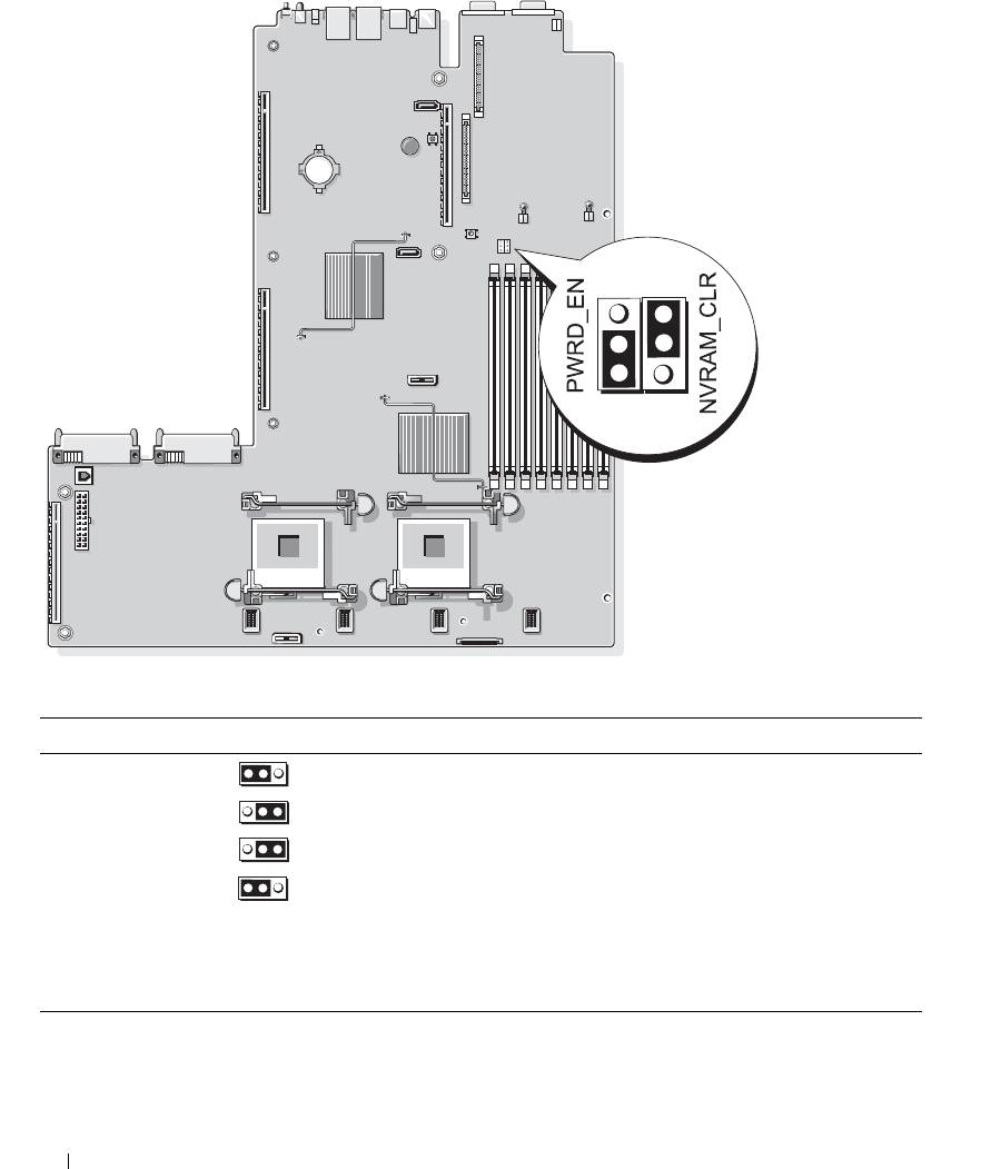
Figure 6-1. System Board Jumpers
Table 6-1. System Board Jumper Settings
Jumper Setting Description
1PWRD_EN
(default)
The password feature is enabled.
The password feature is disabled.
2NVRAM_CLR
(default)
The configuration settings are retained at system boot.
The configuration settings are cleared at the next system
boot. (If the configuration settings become corrupted to the
point where the system will not boot, install the jumper and
boot the system. Remove the jumper before restoring the
configuration information.)
NOTE: For the full name of an abbreviation or acronym used in this table, see the "Glossary" on page 147.
116 Jumpers and Connectors

Disabling a Forgotten Password
The system's software security features include a system password and a setup password, which are discussed in
detail in "Using the System Setup Program" on page 31. The password jumper enables these password features
or disables them and clears any password(s) currently in use.
NOTICE: See "Protecting Against Electrostatic Discharge" in the safety instructions in your Product Information
Guide.
1
Turn off the system, including any attached peripherals, and disconnect the system from the electrical
outlet.
2
Open the system. See "Opening and Closing the System" on page 46.
3
Lift up the memory module shroud.
4
Remove the jumper plug from the password jumper.
See Figure 6-1 to locate the password jumper on the system board.
5
Close the system.
6
Reconnect your system and peripherals to their electrical outlets, and turn on the system.
The existing passwords are not disabled (erased) until the system boots with the password jumper plug
removed. However, before you assign a new system and/or setup password, you must install the jumper
plug.
NOTE: If you assign a new system and/or setup password with the jumper plug still removed, the system
disables the new password(s) the next time it boots.
7
Turn off the system, including any attached peripherals, and disconnect the system from the electrical
outlet.
8
Open the system. See "Opening and Closing the System" on page 46.
9
Install the jumper plug on the password jumper.
10
Lower the memory module shroud.
11
Close the system.
12
Reconnect your system and peripherals to their electrical outlets, and turn on the system.
13
Assign a new system and/or setup password.
To assign a new password using the System Setup program, see "Assigning a System Password" on
page 38.
Jumpers and Connectors 117
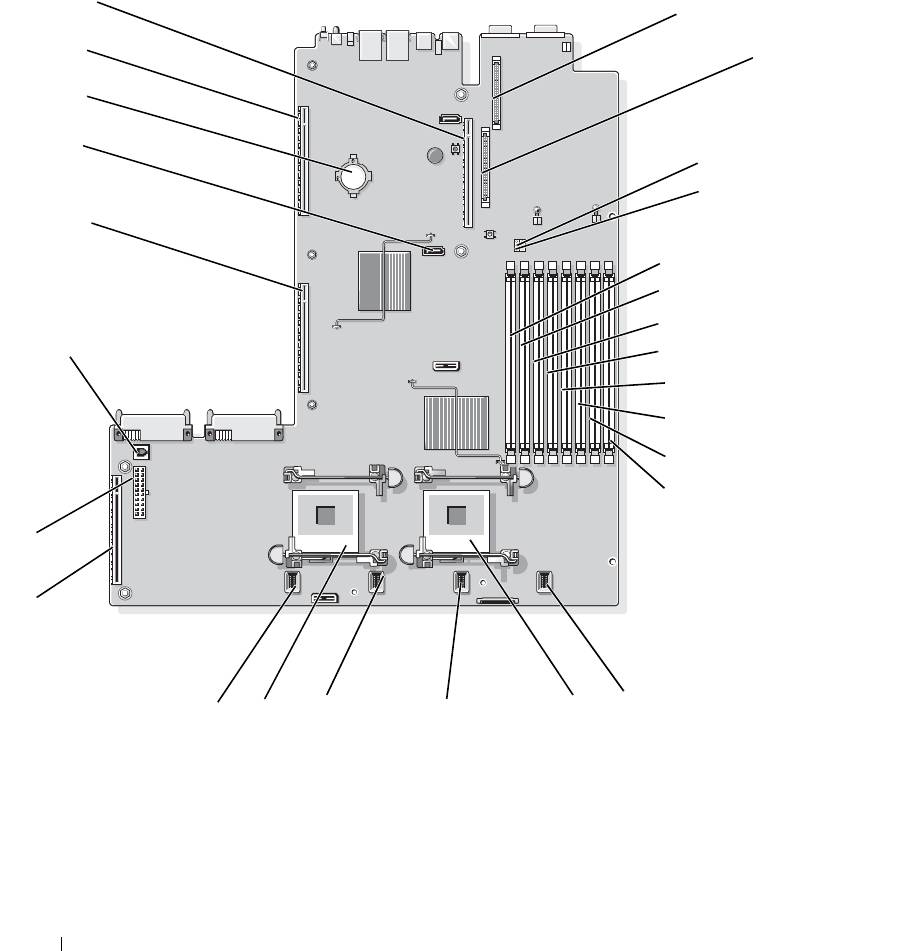
System Board Connectors
See Figure 6-2 and Table 6-2 for the location and description of system board connectors.
Figure 6-2. System Board Connectors
26
1
25
2
24
23
3
4
22
5
6
7
21
8
9
10
11
12
2
1
16
13
18
17
15
14
118 Jumpers and Connectors

Table 6-2. System Board Connectors
Connector Description
1 RAC_CONN2 Connector for the remote access control connector (RAC)
2 RAC_CONN1 Connector for the remote access control connector
3 NVRAM_CLR Configuration jumper
4 PWRD_EN Password jumper
5 DIMM 1 Memory module connector, slot 1
6 DIMM 5 Memory module connector, slot 5
7 DIMM 2 Memory module connector, slot 2
8 DIMM 6 Memory module connector, slot 6
9 DIMM 3 Memory module connector, slot 3
10 DIMM 7 Memory module connector, slot 7
11 DIMM 4 Memory module connector, slot 4
12 DIMM 8 Memory module connector, slot 8
13 FAN_MOD4 System cooling fan module 4 connector
14 CPU1 Microprocessor connector 1
15 FAN_MOD3 System cooling fan module 3 connector
16 FAN_MOD2 System cooling fan module 2 connector
17 CPU2 Microprocessor connector 2
18 FAN_MOD1 System cooling fan module 1 connector
19 SIDEPLANE Sideplane connector
20 BACKPLANE Backplane power connector
21 TOE_KEY TCP/IP offload engine key
22 LEFT PCIe RISER Left riser board connector
23 SATA_A SATA A connector
24 BATTERY Connector for the 3.0-V coin battery
25 LEFT PCI-X RISER Left riser board connector (PCIe or PCI-X)
26 CENTER RISER Center riser board connector (PCIe or PCI-X)
NOTE: For the full name of an abbreviation or acronym used in this table, see the "Glossary" on page 147.
Jumpers and Connectors 119
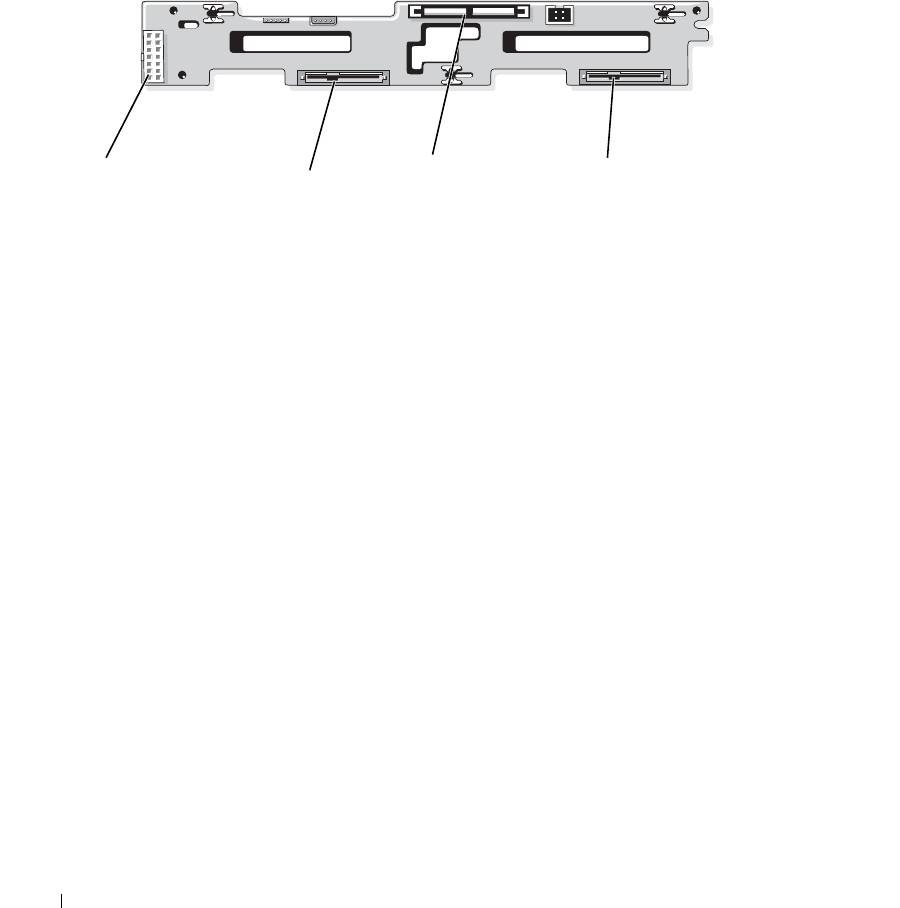
SAS/SATA Backplane Board Connectors
Figure 6-3 shows the location of the connectors on the SAS/SATA backplane board that supports two 3.5-inch
hard drives (Option 1).
Figure 6-3. SAS 3.5-Inch-Drive Backplane Board Components - Option 1
1
3
4
2
1 backplane power connector 2 Drive 0 connector 3 SAS A connector
4 Drive 1 connector
Figure 6-4 and Figure 6-5 show the location of the connectors on the SAS/SATA backplane board that supports
four 2.5-inch hard drives (Option 2).
120 Jumpers and Connectors
