Dell PowerEdge 1950 – страница 3
Инструкция к Компьютеру Dell PowerEdge 1950
Оглавление

The password assignment is not case-sensitive. However, certain key combinations are not valid. If you
enter one of these combinations, the system beeps. To erase a character when entering your password, press
<Backspace> or the left-arrow key.
After you verify the password, the Setup Password setting changes to Enabled. The next time you enter the
System Setup program, the system prompts you for the setup password.
A change to the Setup Password option becomes effective immediately (restarting the system is not
required).
Operating With a Setup Password Enabled
If Setup Password is set to Enabled, you must enter the correct setup password before you can modify
most of the System Setup options. When you start the System Setup program, the program prompts you to
enter a password.
If you do not enter the correct password in three attempts, the system lets you view, but not modify, the
System Setup screens—with the following exception: If System Password is not set to Enabled and is not
locked through the Password Status option, you can assign a system password (however, you cannot
disable or change an existing system password).
NOTE: You can use the Password Status option in conjunction with the Setup Password option to protect the
system password from unauthorized changes.
Deleting or Changing an Existing Setup Password
1
Enter the System Setup program and select the
System Security
option.
2
Highlight the
Setup Password
option, press <Enter> to access the setup password window, and press
<Enter> twice to clear the existing setup password.
The setting changes to
Not Enabled
.
3
If you want to assign a new setup password, perform the steps in "Assigning a Setup Password" on
page 40.
Disabling a Forgotten Password
See "Disabling a Forgotten Password" on page 117.
Baseboard Management Controller Configuration
The Baseboard Management Controller (BMC) enables configuring, monitoring, and recovery of systems
remotely. BMC provides the following features:
• Uses the system’s integrated NIC
• Fault logging and SNMP alerting
• Access to system event log and sensor status
• Control of system functions including power on and off
Using the System Setup Program 41

• Support is independent of the system’s power or operating state
• Provides text console redirection for system setup, text-based utilities, and operating system consoles
NOTE: To remotely access the BMC through the integrated NIC, you must connect the network connection to
integrated NIC1.
For additional information on using BMC, see the documentation for the BMC and systems management
applications.
Entering the BMC Setup Module
1
Turn on or restart your system.
2
Press <
Ctrl-E
> when prompted after POST.
If your operating system begins to load before you press <
Crtl-E
>, allow the system to finish booting,
and then restart your system and try again.
BMC Setup Module Options
For information about the BMC Setup Module options and how to configure the emergency management port
(EMP), see the
BMC User’s Guide
.
42 Using the System Setup Program

3
Installing System Components
This section describes how to install the following system components:
• Cooling fan modules
• Cooling shrouds
• Power supplies
• SAS controller daughter card or SAS RAID controller daughter card
• RAID battery
• RAID controller expansion card
• Expansion cards
• Boot drive
• System memory
• Processors
• RAC card
• Optical drive
• Hard drives
• SAS backplane boards
•Risers
• Sideplane board
• System battery
• Control panel assembly
• System board
Installing System Components 43
Recommended Tools
You may need the following items to perform the procedures in this section:
• Key to the system keylock
• #2 Phillips screwdriver
• T10 Torx driver
• Small flat-blade screwdriver
• Wrist grounding strap
Inside the System
CAUTION: Many repairs may only be done by a certified service technician. You should only perform
troubleshooting and simple repairs as authorized in your product documentation, or as directed by the online or
telephone service and support team. Damage due to servicing that is not authorized by Dell is not covered by your
warranty. Read and follow the safety instructions that came with the product.
CAUTION: The memory modules can become extremely hot during normal operation. Allow the modules
sufficient time to cool before handling.
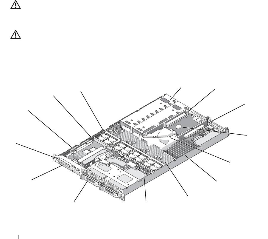
In Figure 3-1, the bezel, system cover, and memory cooling shroud are removed to provide an interior view
of the system.
Figure 3-1. Inside the System
5
4
6
3
7
2
8
1
9
14
10
11
13
12
44 Installing System Components

1 control panel 2 SAS controller daughter card
3 sideplane
or SAS RAID controller
daughter card (optional)
4 cooling fan modules (4) 5 power supply bays (2) 6 left riser (slot 2)
7 center riser (slot 1) 8 battery 9 system board cooling shroud
1
memory modules (8) 11 heatsink/microprocessor (2) 12 backplane
0
1
two 3.5-inch or four 2.5-inch
14 optical slimline drive
3
hard drive bays
(optional)
The system board holds the system's control circuitry and other electronic components. Several hardware
options, such as the microprocessors and memory, are installed directly on the system board. The left and
center risers each have one slot and can accommodate up to two half-length PCI-X cards or two half-length
PCIe expansion cards. For more information, see "Expansion Cards" on page 61.
The system provides space for one optional slimline optical drive. The optical drive tray connects to the
controller on the system board through the sideplane board. For more information, see "Installing the Optical
Drive Tray" on page 74.
The hard-drive bays provide space for up to two 3.5-inch or four 2.5-inch SAS/SATA hard drives. The hard
drives connect to a SAS controller daughter card or a SAS RAID controller daughter card. For more
information, see "Installing a Hot-Plug Hard Drive" on page 76.
During an installation or troubleshooting procedure, you may be required to change a jumper setting. For
more information, see "Jumpers and Connectors" on page 115.
NOTE: There are no hot-pluggable components inside this system except for externally accessible components,
such as the power supplies and the hard drives.
Removing and Replacing the Front Bezel
1
The system is enclosed by an optional bezel. To upgrade or troubleshoot the system, remove the bezel and
cover to access the internal system components. Unless you are installing a hot-plug hard drive, turn off
the system and attached peripherals, and disconnect the system from the electrical outlet and peripherals.
NOTE: You do not need to remove the front bezel to remove the system cover.
2
Using the system key, unlock the bezel.
3
Press the tab at the left end of the bezel.
4
Rotate the left end of the bezel away from the system to release the right end of the bezel.
5
Pull the bezel away from the system. See Figure 3-2.
Installing System Components 45
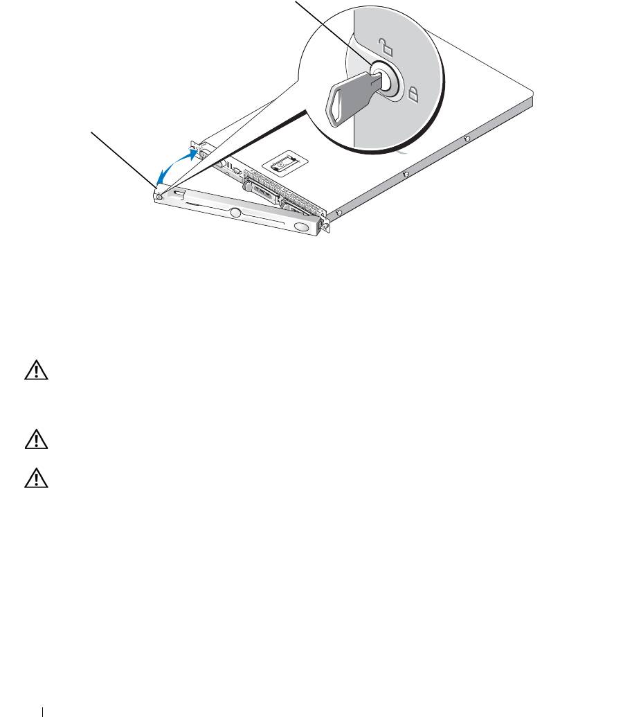
Figure 3-2. Removing the Bezel
1
2
1 key lock 2 bezel cover
To replace the front bezel, perform the preceding steps in reverse.
Opening and Closing the System
CAUTION: Many repairs may only be done by a certified service technician. You should only perform
troubleshooting and simple repairs as authorized in your product documentation, or as directed by the online or
telephone service and support team. Damage due to servicing that is not authorized by Dell is not covered by your
warranty. Read and follow the safety instructions that came with the product.
CAUTION: Whenever you need to lift the system, get others to assist you. To avoid injury, do not attempt to lift
the system by yourself.
CAUTION: The memory modules can become extremely hot during normal operation. Allow the modules
sufficient time to cool before handling.
Opening the System
To upgrade or troubleshoot the system, remove the system cover to gain access to internal components.
1
Turn off the system and attached peripherals, and disconnect the system from the electrical outlet and
peripherals.
2
Remove the bezel. See "Removing and Replacing the Front Bezel" on page 45.
3
To remove the system cover, rotate the latch release lock on the latch in a counter clockwise direction to
the unlocked position. See Figure 3-3.
46 Installing System Components
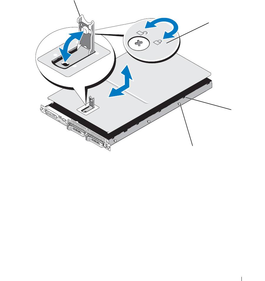
4
Lift up on the latch on top of the system to guide it back and into an offset position. See Figure 3-3.
5
Grasp the cover on both sides and carefully lift the cover away from the system.
Figure 3-3. Removing the Cover
1
2
3
4
1 latch 2 latch release lock 3 alignment J hooks
4 chassis tabs
Closing the System
1
Lift up the latch on the cover.
2
Place the cover on top of the system and offset the cover slightly back so that it clears the chassis J hooks
and lays flat on the system chassis. See Figure 3-3.
3
Lower the cover into the closed position aligning it with the J hooks and push down on the latch to guide
the cover into place.
4
Rotate the latch release lock in a clockwise direction to secure the cover.
Installing System Components 47
Cooling Fan Modules
This system contains four cooling fan modules, each comprised of two dual-rotor fans, for a total of eight fans
that are connected directly to the system board.
Removing a Cooling Fan Module
CAUTION: Many repairs may only be done by a certified service technician. You should only perform
troubleshooting and simple repairs as authorized in your product documentation, or as directed by the online or
telephone service and support team. Damage due to servicing that is not authorized by Dell is not covered by your
warranty. Read and follow the safety instructions that came with the product.
NOTE: The procedure for removing each individual fan module is the same.
1
Turn off the system and attached peripherals, and disconnect the system from the electrical outlet and
peripherals.
2
Open the system. See "Opening and Closing the System" on page 46.
NOTE: You can remove the fan modules without removing the memory cooling shroud; however, Dell
recommends that you remove this shroud before removing a fan module. Do not remove the system board cooling
shroud.
See "Removing the Memory Cooling Shroud" on page 52.
3
Raise the fan handle, disconnect the module wire harness from the system board, and pull the fan straight
up to clear the chassis. See Figure 3-4.
4
Unplug the fan module connector.
48 Installing System Components
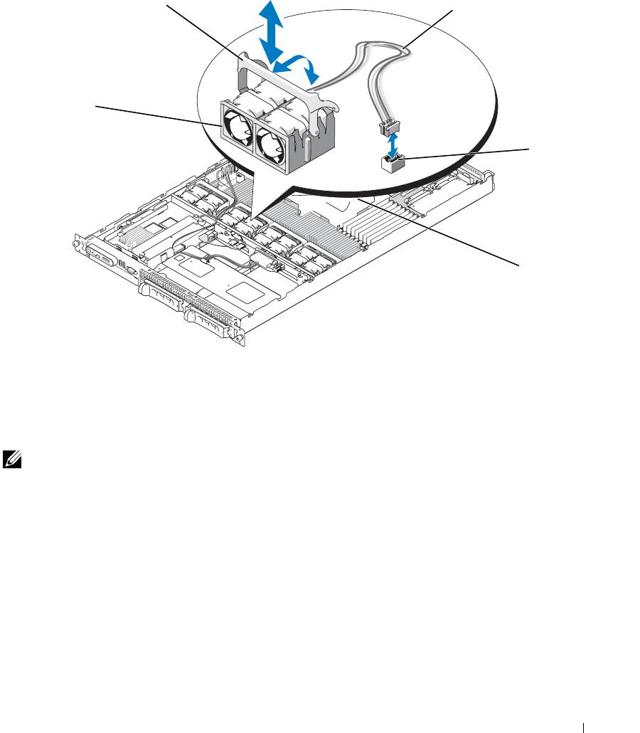
Figure 3-4. Removing and Installing a Cooling Fan
2
3
1
4
5
1 cooling fan modules (4) 2 fan module handles 3 module wire harness
4 cooling fan module connector 5 system board cooling shroud
Replacing a Cooling Fan Module
NOTE: The procedure for installing each individual fan is the same.
1
Ensure that the fan handle is upright and lower the fan into its retention base until the fan is fully seated.
Then lower the fan handle until it snaps into place. See Figure 3-4.
2
Attach the fan module connectors.
3
If you removed the memory cooling shroud to access the fan modules, replace the shroud. See "Replacing
the Memory Cooling Shroud" on page 53.
4
Close the system. See "Opening and Closing the System" on page 46.
Installing System Components 49

Removing the Plastic Fan Guide
NOTE: The plastic fan guide is mounted to the chassis between the fans.
NOTE: You may need to remove the system from the rack.
1
Remove the cooling fan modules. See "Removing a Cooling Fan Module" on page 48.
2
Remove the system from the rack. See the Rack Installation Guide for your system.
3
Place the system upside-down on a flat surface.
4
Using a #2 Phillips screwdriver, remove the two screws from the bottom of the chassis that secure the fan
bracket.
5
Turn the system right-side up, place it on a flat surface, and then remove the fan bracket.
Replacing the Plastic Fan Guide
1
While the system is out of the rack, and with the top cover removed, place the system on its side on a flat
surface.
2
Place the fan bracket into its location inside the chassis.
3
Holding the fan bracket in place, use a #2 Phillips screwdriver to replace the two screws on the bottom of
the chassis.
4
Place the system right-side up on a flat surface.
5
Replace the cooling fan modules. See "Replacing a Cooling Fan Module" on page 49.
6
Replace the system in the rack. See the Rack Installation Guide for your system.
Cooling Shrouds
Your system contains two cooling shrouds.
• System board cooling shroud
• Memory cooling shroud
System Board Cooling Shroud
The
system board cooling shroud directs airflow over the system memory modules, channeling the air from the
four fan modules. See Figure 3-5.
50 Installing System Components
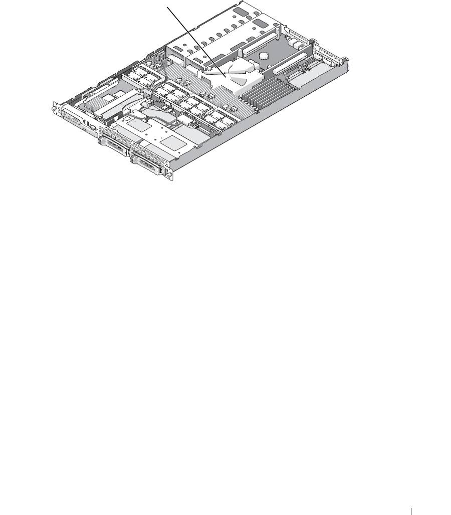
Figure 3-5. System Board Cooling Shroud
1
1 system board cooling shroud
Removing the System Board Cooling Shroud
1
If applicable, remove the bezel. See "Removing and Replacing the Front Bezel" on page 45.
2
Turn off the system and attached peripherals, and then disconnect the system from the electrical outlet.
3
Open the system. See "Opening the System" on page 46.
4
Remove the memory cooling shroud. See "Removing the Memory Cooling Shroud" on page 52.
5
Remove both the center and left risers from the system board. See "Removing an Expansion-Card Riser"
on page 82.
6
Press the tabs on the front side of the shroud (nearest to the processors), and then lift the shroud up and
away from the system.
Installing the System Board Cooling Shroud
1
Align the back of the shroud to the front of the posts of the center and rear card risers on the motherboard.
2
Press down gently on the front of the shroud until it engages with the plastic tabs on the motherboard.
3
Place the center and left risers. See "Installing an Expansion-Card Riser" on page 83.
4
Replace the memory cooling shroud. See "Replacing the Memory Cooling Shroud" on page 53.
5
Close the system. See "Closing the System" on page 47.
Installing System Components 51
6
If applicable, replace the bezel. See "Removing and Replacing the Front Bezel" on page 45.
7
Attach any peripherals, connect the system to the electrical source, and then turn on the system.
Memory Cooling Shroud
The memory cooling shroud covers both the memory modules (DIMMs) and the processors. This shroud can be
removed and installed. See Figure 3-6 and "System Board Removal" on page 91.
Removing the Memory Cooling Shroud
CAUTION: Many repairs may only be done by a certified service technician. You should only perform
troubleshooting and simple repairs as authorized in your product documentation, or as directed by the online or
telephone service and support team. Damage due to servicing that is not authorized by Dell is not covered by your
warranty. Read and follow the safety instructions that came with the product.
CAUTION: The memory modules are hot to the touch for some time after the system has been powered down.
Allow time for the memory modules to cool before handling them. Handle the memory modules by the card edges
and avoid touching the components on the memory module.
NOTICE: Never operate your system with the memory cooling shroud removed. Overheating of the system can
develop quickly resulting in a shutdown of the system and the loss of data.
1
To remove the cooling shroud, locate the release tab on the shroud edge that is nearest to the adjacent
system board shroud. See Figure 3-6.
2
Pull up on the release tab to release the memory cooling shroud.
3
Unseat the shroud from the securing tabs located on the periphery of the shroud.
4
Carefully lift the shroud straight up to disengage it from the system board, and then lift the shroud away
from the system.
52 Installing System Components
Figure 3-6. Memory Cooling Shroud
1
2
3
4
1 memory cooling shroud 2 memory shroud release tab 3 memory modules (8)
4 system processors (2)
Replacing the Memory Cooling Shroud
1
To install the memory cooling shroud, align the shroud directly over the memory modules and the
processors.
2
Using the interior system board cooling shroud as a guide, slowly lower the shroud straight down onto the
system, directly over the processors and memory modules.
3
Gently press around the periphery of the shroud until it engages with the external tabs and snaps into
place.
Power Supplies
Your system supports one or two power supplies rated at an output of 670 W. If only one power supply is
installed, it must be installed in the left power supply bay (bay 1). If two power supplies are installed, the
second power supply serves as a redundant, hot-plug power source.
NOTICE: In a non-redundant configuration, the power supply blank must be installed in the unoccupied power
supply bay to ensure proper system cooling. See "Installing the Power Supply Blank" on page 56.
Installing System Components 53

Removing a Power Supply
NOTICE: The system requires one power supply for the system to operate normally. The system is in the
redundant mode when two power supplies are installed and both power supplies are connected to an AC power
source. Remove and replace only one power supply at a time in a system that is powered on. Operating the system
with only one power supply installed and without a power supply blank installed for extended periods of time can
cause the system to overheat.
NOTICE: If only one power supply is installed, it must be installed in the left power supply bay (1).
NOTICE: If you connect the system to a power source in the range of 120 to 220 VAC, and if two power supplies
are installed, the second power supply serves as a redundant, hot-plug power source.
NOTE: On your rack system, you may have to unlatch and lift the cable management arm if it interferes with
power supply removal. For information about the cable management arm, see the system’s Rack Installation
Guide.
1
If your system has a single power supply, turn off the system and all attached peripherals. For a redundant
system, you can leave the system running and proceed to the next step.
2
Disconnect the power cable from the power source.
3
Disconnect the power cable from the power supply and remove the cable from the cable retention bracket.
NOTICE: On a rack system, you may need to temporarily unlatch and lift the cable management arm. For
information about the cable management arm, see the system’s Rack Installation Guide.
4
Release the locking tab on the left side of the power supply by pressing in toward the right until the power
supply is released from the chassis. See Figure 3-7.
5
Holding the power-supply handle, pull the power supply straight out to clear the chassis.
54 Installing System Components
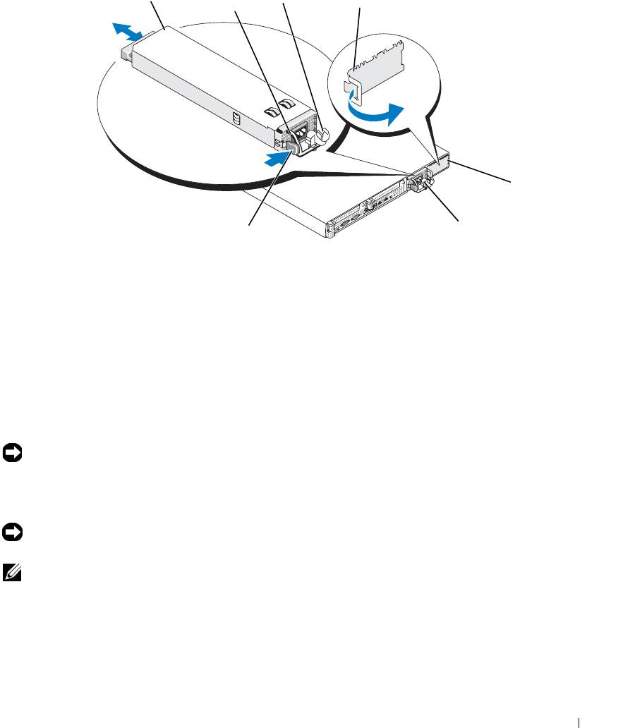
Figure 3-7. Removing and Installing a Power Supply
3
1
2
4
5
6
7
1 power-supply 2 power-supply handle 3 cable retention bracket
4 power supply blank 5 power-supply bay 2 (optional) 6 redundant power supply bay 1
7 locking tab
Replacing a Power Supply
1
If you are adding a second power supply, remove the power supply blank. See "Removing a Power
Supply" on page 54.
2
Holding the power-supply handle, slide the new power supply into the chassis until it is fully seated and
contacts the system chassis. See Figure 3-7.
NOTICE: On a rack system, you may need to temporarily unlatch and lift the cable management arm. For
information about the cable management arm, see the system’s Rack Installation Guide.
3
Insert the power cable through the cable retention bracket, connect the power cable to the power supply,
and plug the cable into a power outlet.
NOTICE: For more information about the power cable retention bracket, see the Getting Started With Your
System guide.
NOTE: After installing a new power supply in a system with two power supplies, allow several seconds for the
system to recognize the power supply and determine its status. The power-supply status indicator turns green to
signify that the power supply is functioning properly (see Figure 1-4).
Installing System Components 55
Removing the Power Supply Blank
Press the latch on the left side to release and remove the blank, rotating the blank slightly to clear the bay,
and remove from the chassis.
NOTICE: To ensure proper system cooling, the power supply blank must be installed on the unoccupied power
supply bay in a non-redundant configuration. Remove the power supply blank only if you are installing a second
power supply.
Installing the Power Supply Blank
To install the power supply blank, insert the tab on the right edge of the blank into the slot in the power
supply bay wall. Rotate the blank into the power supply bay until it is fully seated.
SAS Controller Daughter Card
Your system includes a dedicated slot on the sideplane for an optional SAS controller daughter card. The
SAS controller daughter card provides the SAS storage subsystem for your system’s two optional internal
hard drives. The optional SAS RAID controller daughter card allows you to set up any internal hard drives
in a RAID configuration.
Removing a SAS Controller Daughter Card
1
If you are removing a SAS RAID controller daughter card, disconnect the battery cable from the card by
releasing the tab on the cable connector on the daughter card. See Figure 3-26.
2
Pull on the release latch on the daughter card (see Figure 3-8) and slide the daughter card tray towards the
hard drives.
3
Continue to hold the guide rails outward as you pull the SAS controller daughter card upward from the
rails.
Installing a SAS Controller Daughter Card or SAS RAID Controller Daughter Card
NOTICE: If you are installing a SAS RAID daughter card, be careful not to press on the memory module on the
card (see Figure ). to avoid damaging the memory module or its socket.
NOTICE: If you are installing a new or replacement SAS RAID daughter card, do not remove the card’s plastic
cover until you have completed installing the card.
1
Hold the metal daughter card tray by its edges with the release latch and edge connector facing the
sideplane board. See Figure 3-8.
2
Align the two slots in the daughter card tray and the corresponding tabs on the chassis, then lower the card
tray onto the chassis.
3
Slide the daughter card tray towards the sideplane until the edge connector on the daughter card fits into
the socket on the sideplane board and the release latch engages. See Figure 3-8.
56 Installing System Components
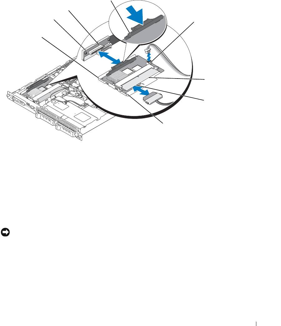
Figure 3-8. Installing a SAS Controller Daughter Card
4
3
2
5
1
6
7
8
1 SAS controller daughter card
2 sideplane 3 daughter card socket
and tray assembly
4 release latch 5 RAID battery connector (SAS
6 RAID memory module
RAID controller daughter card
(DIMM) (SAS RAID
only)
controller daughter card only)
7 SAS RAID connector 0 (to
8 alignment slots in card tray (2)
backplane SAS A)
4
Attach any cables from the internal storage daughter card to the backplane, referring to Figure 3-9 and
Figure 3-10 for the cabling guidelines for your system’s card and backplane configuration.
NOTICE: You must follow the cabling diagrams for connecting the hard drives to either of the internal storage
daughter cards that are illustrated in the following figures to ensure proper connection. Figure 3-9 illustrates the
cable routing for the SAS controller daughter card and Figure 3-10 illustrates the cable routing for the SAS RAID
controller daughter card.
Installing System Components 57
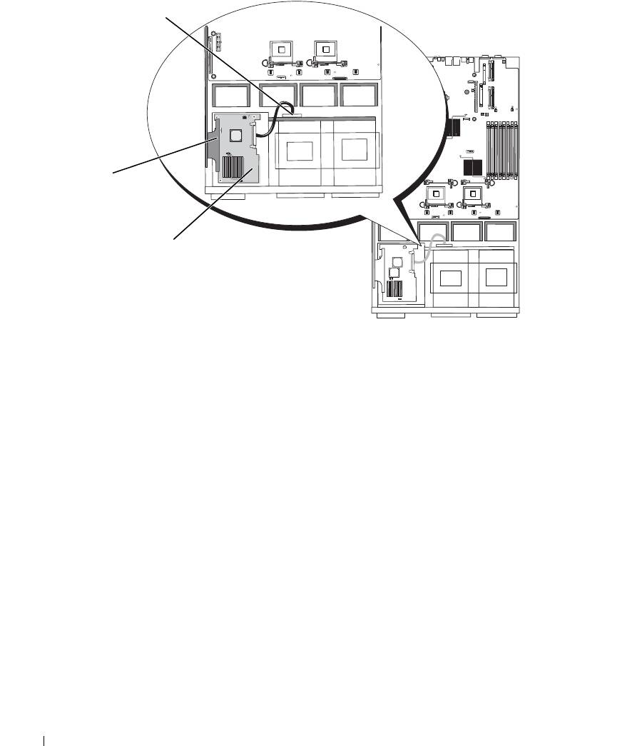
Figure 3-9. Cable Routing for the SAS Controller Daughter Card
3
2
1
1 SAS connector SAS 0 2 SAS controller daughter card 3 SAS backplane connector
SAS A
58 Installing System Components
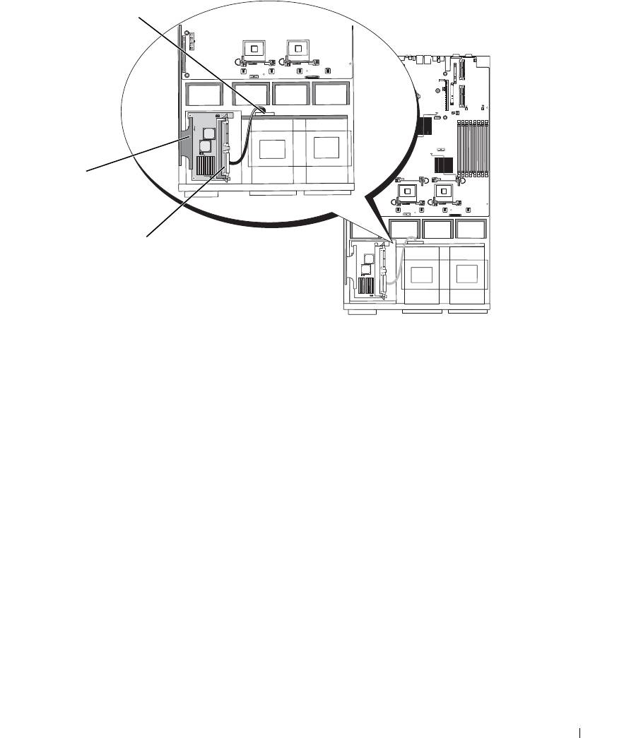
Figure 3-10. Cable Routing for the SAS RAID Controller Daughter Card
3
2
1
1 SAS RAID connector SAS 0 2 SAS RAID controller
3 SAS backplane connector
daughter card
SAS A
Installing System Components 59
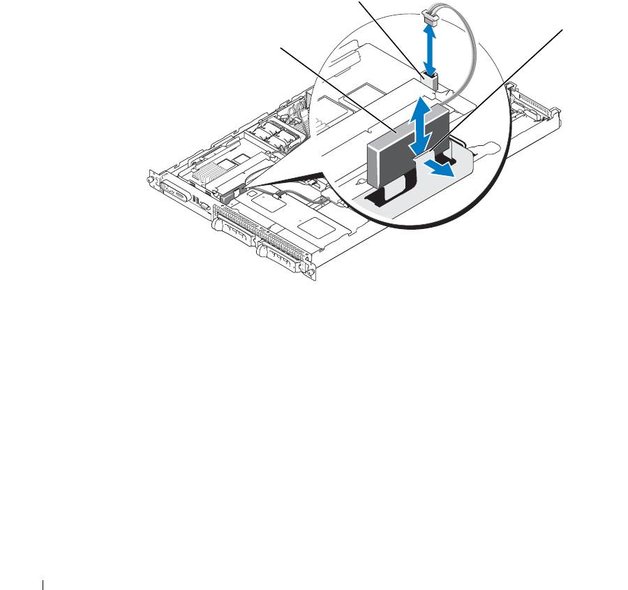
RAID Battery
Installing a RAID Battery
1
Locate the RAID battery pocket on the chassis that is adjacent to hard drive bay 0. See Figure 3-11.
2
Insert the battery in the battery pocket.
3
Connect the battery cable to the RAID controller daughter card. See Figure 3-11.
Figure 3-11. Installing a SAS RAID Battery
2
3
1
1 RAID battery 2 SAS RAID daughter card
3 release latch
battery connector
Removing a RAID Battery
1
Disconnect the RAID battery cable from the SAS RAID daughter card. See Figure 3-11.
2
Press the release latch toward the hard-drive bays and remove the battery from the battery pocket.
60 Installing System Components
