Dell PowerEdge 1950 – страница 5
Инструкция к Компьютеру Dell PowerEdge 1950
Оглавление
4
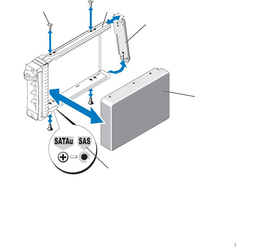
Attach the interposer card to the rear of the SATA hard drive:
a
Angle the top of the interposer card into the inside top carrier rail so that the tabs on the interposer
card bracket attach to the slots on the inside of the carrier rail.
See
Figure 3-21.
b
Rotate the bottom end of the card toward the hard drive to seat the connector.
See
Figure 3-21.
c
Push the bottom end of the card towards the hard drive until the latch on the card bracket clicks into
place.
Figure 3-21. Installing a SATA Hard Drive and Interposer Card Into a SATAu Drive Carrier
1
2
3
4
5
1 screws (4) 2 SATAu drive carrier 3 interposer card (SATA only)
4 SATA hard-drive 5 hole labels
Installing System Components 81
Expansion-Card Riser
Removing an Expansion-Card Riser
CAUTION: Many repairs may only be done by a certified service technician. You should only perform
troubleshooting and simple repairs as authorized in your product documentation, or as directed by the online or
telephone service and support team. Damage due to servicing that is not authorized by Dell is not covered by your
warranty. Read and follow the safety instructions that came with the product.
1
If applicable, remove the bezel. See "Removing and Replacing the Front Bezel" on page 45.
2
Turn off the system and attached peripherals, and disconnect the system from the electrical outlet.
3
Open the system. See "Opening and Closing the System" on page 46.
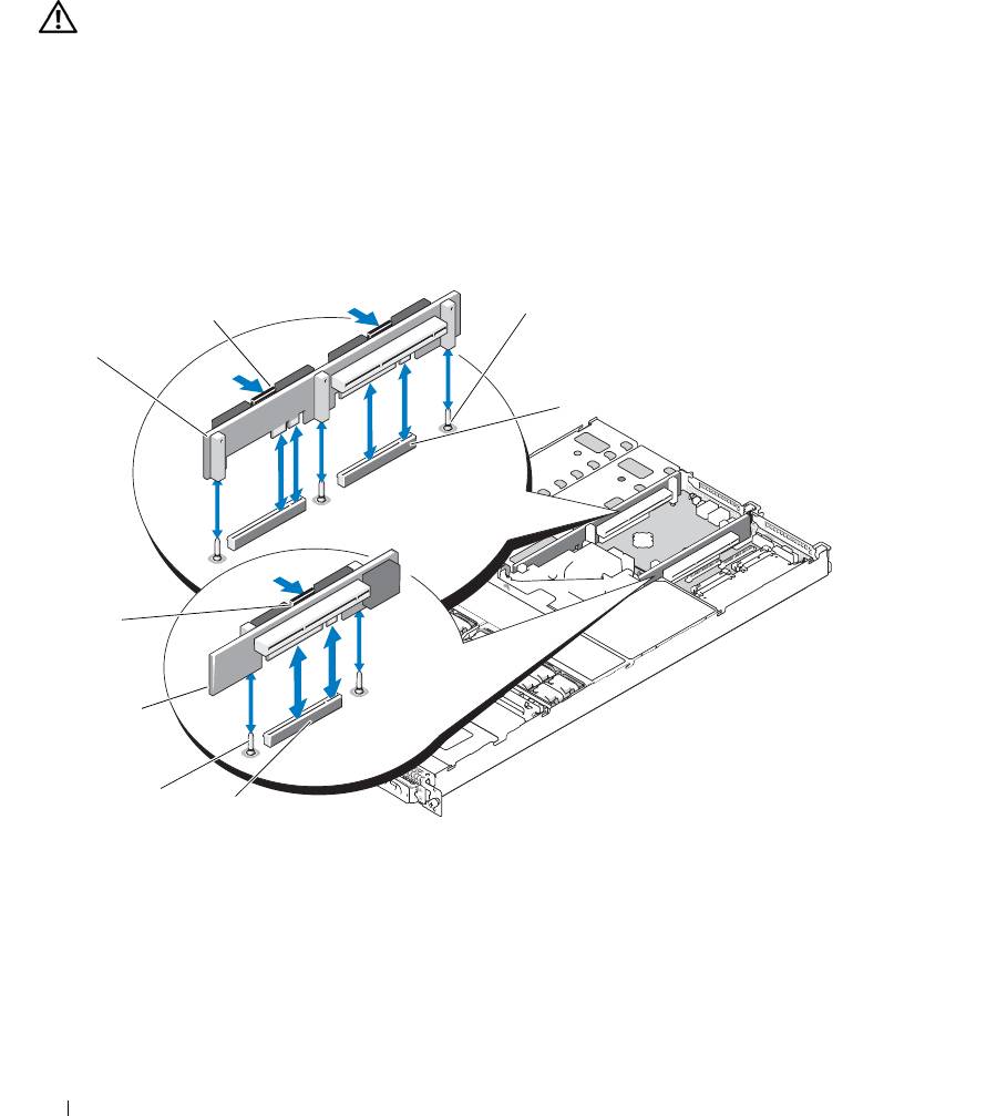
Figure 3-22. Expansion-Card Riser Removal
3
2
1
4
8
7
6
5
1 left riser board 2 left riser board release
3 left riser board alignment
latches (2)
pins (2)
4 left riser board connectors (2) 5 center riser board connector 6 center riser board alignment
pins (2)
7 center riser board 8 center riser board release latch
82 Installing System Components

4
If applicable, remove the expansion card from the riser.
5
Press the release latch(es) on the riser board and lift the riser board straight up from the system board. See
Figure 3-22.
The left riser board has two release latches; the center riser board has one latch.
Installing an Expansion-Card Riser
CAUTION: Many repairs may only be done by a certified service technician. You should only perform
troubleshooting and simple repairs as authorized in your product documentation, or as directed by the online or
telephone service and support team. Damage due to servicing that is not authorized by Dell is not covered by your
warranty. Read and follow the safety instructions that came with the product.
1
Align the riser board with the alignment pins on the system board, then lower the board onto the pins.
2
Press down on the riser board until the edge connector(s) on the board is (are) fully seated in the riser
board connector on the system board. See Figure 3-22.
3
If applicable, install the expansion card in the expansion-card slot.
4
Close the system. See "Opening and Closing the System" on page 46.
5
Replace the bezel. See "Removing and Replacing the Front Bezel" on page 45.
6
Reconnect your system and peripherals to their electrical outlets, and turn on the system.
Backplane Board
Removing the Backplane Board
CAUTION: Many repairs may only be done by a certified service technician. You should only perform
troubleshooting and simple repairs as authorized in your product documentation, or as directed by the online or
telephone service and support team. Damage due to servicing that is not authorized by Dell is not covered by your
warranty. Read and follow the safety instructions that came with the product.
The removal procedure varies slightly, depending on which backplane board you have in your system.
1
If applicable, remove the bezel. See "Removing and Replacing the Front Bezel" on page 45.
2
Turn off the system and attached peripherals, and disconnect the system from the electrical outlet.
3
Open the system. See "Opening and Closing the System" on page 46.
4
Remove the hard drives.
NOTICE: To properly reinstall the hard drives, ensure that you record which hard drive you remove from
which bay.
5
Disconnect the SAS cable and power cable from the backplane.
– If you are removing a 3.5-inch hard drive (two-drive) backplane, see Figure 3-23.
– If you are removing a 2.5-inch hard drive (four-drive) backplane, see Figure 6-4.
Installing System Components 83
6
Remove the backplane board:
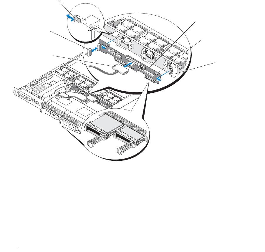
– If you are removing a 3.5-inch hard drive (two-drive) backplane, press the release latch at the left end
of the board, slide the board to its right, and lift the backplane off of the securing tabs. See
Figure 3-23.
– If you are removing a 2.5-inch hard drive (four-drive) backplane, press the release latch at each end of
the backplane and lift the backplane off of the securing tabs. See Figure 6-4.
Figure 3-23. 2.5-Inch Hard Drive Backplane Board Removal and Installation
1
2
6
3
5
4
1 backplane board release latch 2 backplane board 3 securing slots
4 securing tabs 5 SAS interface cable 6 power cable
84 Installing System Components
Installing the Backplane Board
CAUTION: Many repairs may only be done by a certified service technician. You should only perform
troubleshooting and simple repairs as authorized in your product documentation, or as directed by the online or
telephone service and support team. Damage due to servicing that is not authorized by Dell is not covered by your
warranty. Read and follow the safety instructions that came with the product.
1
Replace the backplane board:
– If you are installing a 3.5-inch hard drive (two-drive) backplane, fit the board onto the securing tabs,
press the release latch at the left end of the board and slide the board to its left. See Figure 3-23.
– If you are installing a 2.5-inch hard drive (four-drive) backplane, fit the board onto the securing tabs
on the back of the drive cage and slide the board downwards until the release latch at each end of the
backplane clicks into place. See Figure 6-4.
2
Connect the SAS cable and power cable to the backplane connectors.
3
Reinstall the hard drives.
NOTE: Reinstall the hard drives in the same drive bays from which they were removed.
4
Close the system.
5
If applicable, replace the bezel.
Sideplane Board
Removing the Sideplane Board
CAUTION: Many repairs may only be done by a certified service technician. You should only perform
troubleshooting and simple repairs as authorized in your product documentation, or as directed by the online or
telephone service and support team. Damage due to servicing that is not authorized by Dell is not covered by your
warranty. Read and follow the safety instructions that came with the product.
1
If applicable, remove the bezel. See "Removing and Replacing the Front Bezel" on page 45.
2
Turn off the system and attached peripherals, and disconnect the system from the electrical outlet.
3
Open the system. See "Opening and Closing the System" on page 46.
4
Remove the SAS controller daughter card. See "Removing a SAS Controller Daughter Card" on page 56.
5
Disconnect the control panel cable and optical drive cable (if applicable) from the sideplane. See
Figure 6-8.
6
Press inward on the two sideplane release latches marked in blue and lift the sideplane up and away from
the system board.
Installing System Components 85
Installing the Sideplane Board
CAUTION: Many repairs may only be done by a certified service technician. You should only perform
troubleshooting and simple repairs as authorized in your product documentation, or as directed by the online or
telephone service and support team. Damage due to servicing that is not authorized by Dell is not covered by your
warranty. Read and follow the safety instructions that came with the product.
1
Align the guide on the end of the sideplane board with the pins on the system board, and lower the
sideplane until that the sideplane connector is fully seated into the connector on the system board.
2
Connect the control panel cable and optical drive cable (if applicable) to the sideplane. See Figure 6-8.
3
Replace the SAS controller daughter card. See "Installing a SAS Controller Daughter Card or SAS RAID
Controller Daughter Card" on page 56.
4
Close the system. See "Opening and Closing the System" on page 46.
5
Replace the bezel. See "Removing and Replacing the Front Bezel" on page 45.
6
Reconnect your system and peripherals to their electrical outlets, and turn on the system.
System Battery
The system battery is a 3.0-volt (V), coin-cell battery.
Replacing the System Battery
CAUTION: Many repairs may only be done by a certified service technician. You should only perform
troubleshooting and simple repairs as authorized in your product documentation, or as directed by the online or
telephone service and support team. Damage due to servicing that is not authorized by Dell is not covered by your
warranty. Read and follow the safety instructions that came with the product.
CAUTION: There is a danger of a new battery exploding if it is incorrectly installed. Replace the battery only
with the same or equivalent type recommended by the manufacturer. Discard used batteries according to the
manufacturer's instructions. See your System Information Guide for additional information.
1
Turn off the system, including any attached peripherals, and disconnect the system from the electrical
outlet.
2
Open the system. See "Opening and Closing the System" on page 46.
3
If an expansion card is installed in the left riser board, remove the card. See "Removing an Expansion
Card" on page 62.
4
Locate the battery socket. See Figure 3-24.
NOTICE: If you pry the battery out of its socket with a blunt object, be careful not to touch the system board with
the object. Ensure that the object is inserted between the battery and the socket before you attempt to pry out the
battery. Otherwise, you may damage the system board by prying off the socket or by breaking circuit traces on the
system board.
NOTICE: To avoid damage to the battery connector, you must firmly support the connector while installing or
removing a battery.
86 Installing System Components
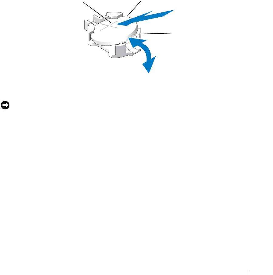
5
Remove the system battery.
a
Support the battery connector by pressing down firmly on the positive side of the connector.
b
While supporting the battery connector, press the battery toward the positive side of the connector and
pry it up out of the securing tabs at the negative side of the connector.
Figure 3-24. Replacing the System Battery
2
1
3
1 positive side of battery
2 system battery 3 negative side of battery
connector
connector
NOTICE: To avoid damage to the battery connector, you must firmly support the connector while installing or
removing a battery.
6
Install the new system battery.
a
Support the battery connector by pressing down firmly on the positive side of the connector.
b
Hold the battery with the "+" facing up, and slide it under the securing tabs at the positive side of the
connector.
c
Press the battery straight down into the connector until it snaps into place.
7
If you removed an expansion card in step 3, replace the card now. See "Installing an Expansion Card" on
page 61.
8
Close the system. See "Opening and Closing the System" on page 46.
9
Reconnect the system to its electrical outlet and turn the system on, including any attached peripherals.
10
Enter the System Setup program to confirm that the battery is operating properly. See "Using the System
Setup Program" on page 31.
11
Enter the correct time and date in the System Setup program's
Time
and
Date
fields.
12
Exit the System Setup program.
13
To test the newly installed battery, turn off the system and disconnect it from the electrical outlet for at
least an hour.
Installing System Components 87
14
After an hour, reconnect the system to its electrical outlet and turn it on.
15
Enter the System Setup program and if the time and date are still incorrect, see "Getting Help" on
page 125 for instructions on obtaining technical assistance.
Control Panel Assembly
Removing the Control Panel
CAUTION: Many repairs may only be done by a certified service technician. You should only perform
troubleshooting and simple repairs as authorized in your product documentation, or as directed by the online or
telephone service and support team. Damage due to servicing that is not authorized by Dell is not covered by your
warranty. Read and follow the safety instructions that came with the product.
1
If applicable, remove the bezel. See "Removing and Replacing the Front Bezel" on page 45.
2
Turn off the system and attached peripherals, and disconnect the system from the electrical outlet.
3
Open the system. See "Opening and Closing the System" on page 46.
4
Remove the SAS controller daughter card. See "Removing a SAS Controller Daughter Card" on page 56.
5
Disconnect the control panel cable at the back of the control panel board. See Figure 3-25.
NOTICE: Do not pull on the cable to unseat the connector. Doing so can damage the cable.
a
Squeeze the metal tabs on the ends of the cable connector.
b
Gently work the connector out of the socket.
6
Disconnect the front panel cable from the control panel board. See Figure 3-25.
7
Lift the release tab at the back of the control panel carrier and slide the carrier towards the back of the
system, then lift the carrier out of the system. See Figure 3-25.
8
Remove the three screws that secure the control panel board to the carrier and remove the board. See
Figure 3-25.
9
Remove the display module:
a
Insert the end of a paper clip into the hole on the right side of the display module and gently pry the
label off.
b
Using a T10 Torx driver, remove the two screws that secure the display module to the system chassis.
See Figure 3-25.
c
Remove the display module from the chassis cutout.
88 Installing System Components
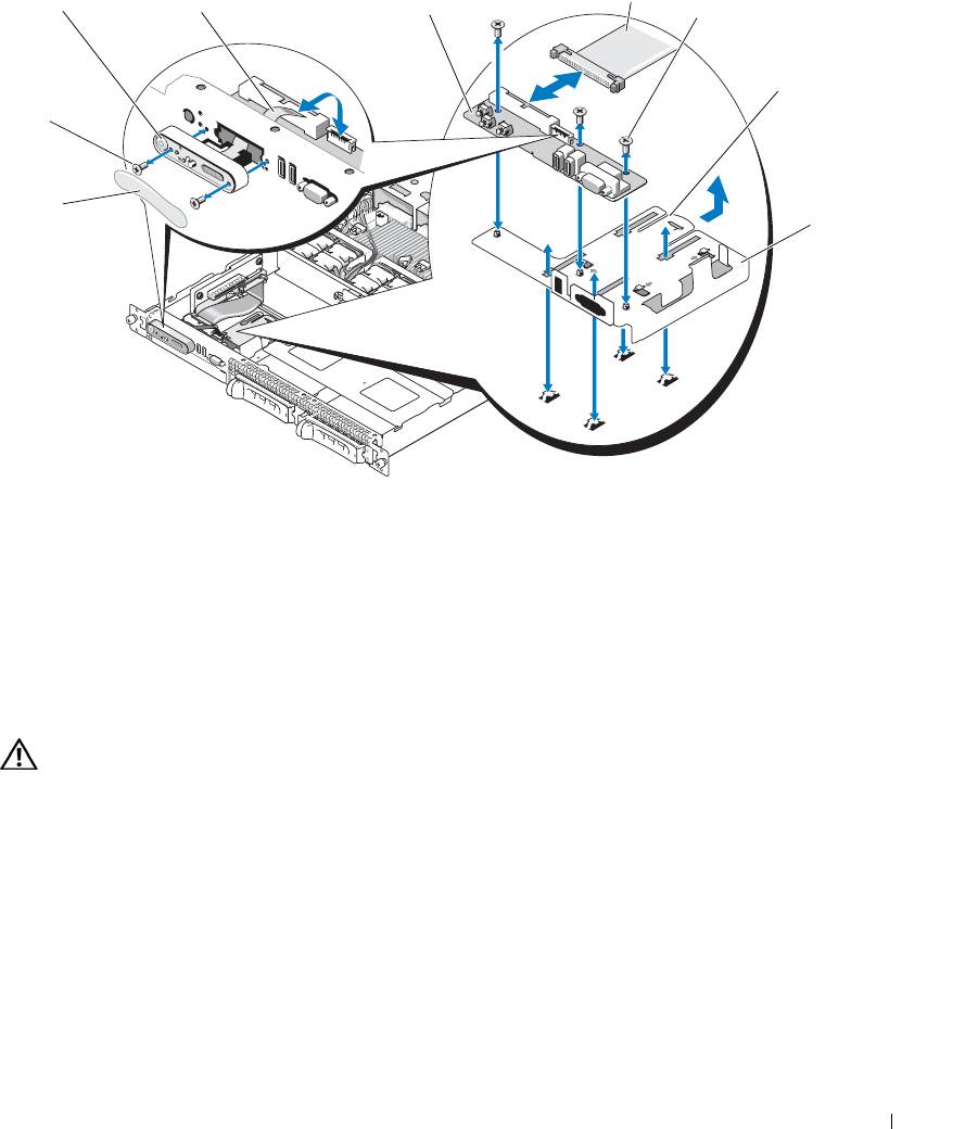
Figure 3-25. Control Panel Removal and Installation
4
1
2
3
5
6
9
8
7
1 display module 2 display module LCD cable 3 control panel circuit board
4 control panel cable 5 control-panel circuit board
6 control panel carrier release
securing screws (3)
tab
7 control panel carrier 8 display module label 9 display module securing
screws (2)
Installing the Control Panel
CAUTION: Many repairs may only be done by a certified service technician. You should only perform
troubleshooting and simple repairs as authorized in your product documentation, or as directed by the online or
telephone service and support team. Damage due to servicing that is not authorized by Dell is not covered by your
warranty. Read and follow the safety instructions that came with the product.
1
Insert the display module into the chassis cutout and secure it with the two screws.
2
Affix the control panel label to the display module.
3
Install the control panel board on the carrier, and secure it with the three Phillips screws. See Figure 3-25.
4
Install the carrier in the system chassis.
5
Connect the display module ribbon cable to the control panel board.
6
Connect the control panel ribbon cable to the control panel board.
Installing System Components 89
7
Replace the SAS controller daughter card. See "Installing a SAS Controller Daughter Card or SAS RAID
Controller Daughter Card" on page 56.
8
Close the system. See "Opening and Closing the System" on page 46.
9
Reconnect the system to the power source and turn on the system and attached peripherals.
10
If applicable, install the bezel. See "Removing and Replacing the Front Bezel" on page 45.
System Board
Removing the System Board
CAUTION: Many repairs may only be done by a certified service technician. You should only perform
troubleshooting and simple repairs as authorized in your product documentation, or as directed by the online or
telephone service and support team. Damage due to servicing that is not authorized by Dell is not covered by your
warranty. Read and follow the safety instructions that came with the product.
1
If applicable, remove the bezel. See "Removing and Replacing the Front Bezel" on page 45.
2
Turn off the system and attached peripherals, and disconnect the system from the electrical outlet.
3
Open the system. See "Opening and Closing the System" on page 46.
4
Disconnect any cables from the system board back panel.
5
Remove the memory cooling shroud. See "Removing the Memory Cooling Shroud" on page 52.
6
Remove both power supplies. See "Removing a Power Supply" on page 54.
7
Remove the sideplane from the system board. See "Removing the Sideplane Board" on page 85.
8
Remove both the center and left risers from the system board. See "Removing an Expansion-Card Riser"
on page 82.
9
Remove the four fan modules. See "Removing a Cooling Fan Module" on page 48.
10
If applicable, remove the RAC card. See "RAC Card" on page 71.
11
Remove the memory modules. See "Removing Memory Modules" on page 67.
CAUTION: The memory modules are hot to the touch for some time after the system has been powered down.
Allow time for the memory modules to cool before handling them. Handle the memory modules by the card edges
and avoid touching the components on the memory module.
NOTE: While removing the memory modules, record the memory module socket locations to ensure proper
installation.
NOTE: Your system also comes with a pre installed system board cooling shroud. Do not remove the
system board cooling shroud. See Figure 3-5.
12
Remove the heatsink(s) and microprocessor(s). See "Removing the Processor" on page 67.
13
If applicable, remove the TOE key. See "Activating the Integrated NIC TOE" on page 67.
90 Installing System Components
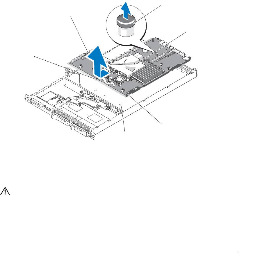
14
Remove the system board:
a
Pull the system-board release pin. See Figure 3-26.
b
While pulling the release pin, grasp the system board release handle and slide the system-board tray
toward the front of the chassis.
c
Lift up the system-board tray and remove it from the chassis.
Figure 3-26. System Board Removal
3
2
4
1
5
6
1 system-board tray release
2 system board attached to
3 system board release pin
handle
system-board tray
4 system board cooling shroud 5 system-board securing tabs 6 system-board securing slots
Installing the System Board
CAUTION: Many repairs may only be done by a certified service technician. You should only perform
troubleshooting and simple repairs as authorized in your product documentation, or as directed by the online or
telephone service and support team. Damage due to servicing that is not authorized by Dell is not covered by your
warranty. Read and follow the safety instructions that came with the product.
1
Lower the system-board tray until the tray sits flat on the bottom of the chassis.
2
Ensure that all system-board securing tabs are fully inserted into the system-board securing slots. See
Figure 3-26.
Installing System Components 91

3
Slide the system-board tray toward the back of the chassis until it locks into position.
4
If applicable, replace the RAC card. See "RAC Card" on page 71.
5
If applicable, replace the TOE key. See "Activating the Integrated NIC TOE" on page 67.
6
Replace the heatsink(s) and microprocessor(s).
7
Replace the memory modules. See "Installing Memory Modules" on page 65.
8
Replace both the center and left risers. See "Installing an Expansion-Card Riser" on page 83.
9
Replace any expansion card(s). See "Installing an Expansion Card" on page 61.
10
Replace the sideplane board. See "Installing the Sideplane Board" on page 86.
11
Replace the fan modules. See "Replacing a Cooling Fan Module" on page 49.
12
Replace the memory cooling shroud. See "Replacing the Memory Cooling Shroud" on page 53.
13
Replace the power supplies. See "Replacing a Power Supply" on page 55.
14
Connect any cables to the system.
15
Close the system. See "Opening and Closing the System" on page 46.
16
Replace the bezel. See "Removing and Replacing the Front Bezel" on page 45.
92 Installing System Components
4
Troubleshooting Your System
Safety First—For You and Your System
To perform certain procedures in this document, you must remove the system cover and work inside the
system. While working inside the system, do not attempt to service the system except as explained in
this guide and elsewhere in your system documentation.
CAUTION: Many repairs may only be done by a certified service technician. You should only perform
troubleshooting and simple repairs as authorized in your product documentation, or as directed by the online
or telephone service and support team. Damage due to servicing that is not authorized by Dell is not covered
by your warranty. Read and follow the safety instructions that came with the product.
Start-Up Routine
Look and listen during the system's start-up routine for the indications described in Table 1-1.
Table 4-1. Start-Up Routine Indications
Look/listen for: Action
A status or error message displayed on the front-panel
See "LCD Status Messages" on page 17.
LCD.
An error message displayed on the monitor. See "System Messages" on page 25.
Alert messages from the systems management software. See the systems management software documentation.
The monitor's power indicator. See "Troubleshooting the Video Subsystem" on page 95.
The keyboard indicators. See "Troubleshooting the Keyboard" on page 95.
The USB CD drive activity indicator. See "Troubleshooting a USB Device" on page 97.
The CD drive activity indicator. See "Troubleshooting an Optical Drive" on page 103.
The hard-drive activity indicator. See "Troubleshooting a Hard Drive" on page 104.
An unfamiliar constant scraping or grinding sound when
See "Getting Help" on page 125.
you access a drive.
Troubleshooting Your System 93

Checking the Equipment
This section provides troubleshooting procedures for external devices attached to the system, such as the
monitor, keyboard, or mouse. Before you perform any of the procedures, see "Troubleshooting External
Connections" on page 94.
Troubleshooting IRQ Assignment Conflicts
Most PCI devices can share an IRQ with another device, but they cannot use an IRQ simultaneously. To
avoid this type of conflict, see the documentation for each PCI device for specific IRQ requirements.
Table 4-2 lists the IRQ assignments.
Table 4-2. IRQ Assignment Defaults
IRQ Line Assignment
IRQ0 System timer
IRQ1 Keyboard controller
IRQ2 Interrupt controller 1 to enable IRQ8 through IRQ15
IRQ3 Available
IRQ4 Serial port 1 (COM1 and COM3)
IRQ5 Remote access controller
IRQ6 Reserved
IRQ7 Reserved
IRQ8 Real-time clock
IRQ9 ACPI functions (used for power management)
IRQ10 Available
IRQ11 Available
IRQ12 Available
IRQ13 Math coprocessor
IRQ14 IDE CD drive controller
IRQ15 Available
Troubleshooting External Connections
Loose or improperly connected cables are the most likely source of problems for the system, monitor, and
other peripherals (such as a printer, keyboard, mouse, or other external device). Ensure that all external
cables are securely attached to the external connectors on your system. See "Front-Panel Features and
Indicators" on page 11 and "Back-Panel Features and Indicators" on page 14 for the front- and back-panel
connectors on your system.
94 Troubleshooting Your System

Troubleshooting the Video Subsystem
Problem
• Monitor is not working properly.
• Video memory is faulty.
Action
1
Check the system and power connections to the monitor.
2
Determine whether the system has an expansion card with a video output connector.
In this system configuration, the monitor cable should normally be connected to the connector on the
expansion card,
not
to the system’s integrated video connector.
To verify that the monitor is connected to the correct video connector, turn off the system and wait for 1
minute, then connect the monitor to the other video connector and turn the system on again.
3
Determine whether the system has monitors attached to both the front and rear video connectors.
The system supports only one monitor attached to either the front or rear video connector. When a monitor
is connected to the front panel, the back-panel video connector is disabled.
If two monitors are attached to the system, disconnect one monitor. If the problem is not resolved,
continue to the next step.
4
Run the appropriate online diagnostic test. See "Using Server Administrator Diagnostics" on page 111.
If the tests run successfully, the problem is not related to video hardware.
If the tests fail, see "Getting Help" on page 125.
Troubleshooting the Keyboard
Problem
• System message indicates a problem with the keyboard
• Keyboard is not functioning properly
Action
1
Examine the keyboard and its cable for signs of damage.
2
Swap the faulty keyboard with a working keyboard.
If the problem is resolved, replace the faulty keyboard. See "Getting Help" on page 125.
3
Enter the System Setup program and ensure that the USB ports are enabled. See "Using the System Setup
Program" on page 31.
If the problem is not resolved, see "Getting Help" on page 125.
4
Run the appropriate online diagnostic test. See "Using Server Administrator Diagnostics" on page 111.
Troubleshooting Your System 95

Troubleshooting the Mouse
Problem
• System message indicates a problem with the mouse.
• Mouse is not functioning properly.
Action
1
Examine the mouse and its cable for signs of damage.
If the mouse is not damaged, go to step 4.
2
Enter the System Setup program and ensure that the USB ports are enabled. See "Using the System Setup
Program" on page 31.
If the mouse is damaged, continue to the next step.
3
Swap the faulty mouse with a working mouse.
If the problem is resolved, replace the faulty mouse. See "Getting Help" on page 125.
4
If the problem is not resolved, see "Getting Help" on page 125.
5
Run the appropriate online diagnostic test. See "Using Server Administrator Diagnostics" on page 111.
If the test fails, continue to the next step.
Troubleshooting Basic I/O Functions
Problem
• Error message indicates a problem with a serial port.
• Device connected to a serial port is not operating properly.
Action
1
Enter the System Setup program and ensure that the serial port is enabled, and the serial port/COM ports
are configured appropriately for any applications you are using. See "Using the System Setup Program"
on page 31.
2
If the problem is confined to a particular application, see the application documentation for specific port
configuration requirements that the program may require.
3
Run the appropriate online diagnostic test. See "Using Server Administrator Diagnostics" on page 111.
If the tests run successfully but the problem persists, see "Troubleshooting a Serial I/O Device" on
page 97.
96 Troubleshooting Your System

Troubleshooting a Serial I/O Device
Problem
• Device connected to the serial port is not operating properly.
Action
1
Turn off the system and any peripheral devices connected to the serial port.
2
Swap the serial interface cable with a working cable, and turn on the system and the serial device.
If the problem is resolved, replace the interface cable.
3
Turn off the system and the serial device, and swap the device with a comparable device.
4
Turn on the system and the serial device.
If the problem is resolved, replace the serial device. See "Getting Help" on page 125.
If the problem persists, see "Getting Help" on page 125.
Troubleshooting a USB Device
Problem
• System message indicates a problem with a USB device.
• Device connected to a USB port is not operating properly.
Action
1
Enter the System Setup program, and ensure that the USB ports are enabled. See "Using the System Setup
Program" on page 31.
2
Turn off the system and any USB devices.
3
Disconnect the USB devices, and connect the malfunctioning device to the other USB connector.
4
Turn on the system and the reconnected device.
If the problem is resolved, the USB connector might be defective. See "Getting Help" on page 125.
5
If possible, swap the interface cable with a working cable.
If the problem is resolved, replace the interface cable. See "Getting Help" on page 125.
6
Turn off the system and the USB device, and swap the device with a comparable device.
7
Turn on the system and the USB device.
If the problem is resolved, replace the USB device. See "Getting Help" on page 125.
If the problem persists, see "Getting Help" on page 125.
Troubleshooting Your System 97
Troubleshooting a NIC
Problem
• NIC cannot communicate with network.
Action
1
Run the appropriate online diagnostic test. See "Running the System Diagnostics" on page 111.
2
Check the appropriate indicator on the NIC connector. See "NIC Indicator Codes" on page 16.
• If the link indicator does not light, check all cable connections.
• If the activity indicator does not light, the network driver files might be damaged or missing.
Remove and reinstall the drivers if applicable. See the NIC documentation.
• Change the autonegotiation setting, if possible.
• Use another connector on the switch or hub.
If you are using a NIC card instead of an integrated NIC, see the documentation for the NIC card.
3
Ensure that the appropriate drivers are installed and the protocols are bound. See the NIC documentation.
4
Enter the System Setup program and confirm that the NICs are enabled. See "Using the System Setup
Program" on page 31.
5
Ensure that the NICs, hubs, and switches on the network are all set to the same data transmission speed.
See the network equipment documentation.
6
Ensure that all network cables are of the proper type and do not exceed the maximum length. See Network
Cable Requirements in your
Getting Started Guide
.
Troubleshooting a Wet System
Problem
• Liquid spilled on the system.
• Excessive humidity.
Action
CAUTION: Many repairs may only be done by a certified service technician. You should only perform
troubleshooting and simple repairs as authorized in your product documentation, or as directed by the online or
telephone service and support team. Damage due to servicing that is not authorized by Dell is not covered by your
warranty. Read and follow the safety instructions that came with the product.
1
Turn off the system and attached peripherals, and disconnect the system from the electrical outlet.
2
Open the system. See "Opening and Closing the System" on page 46.
3
Remove all expansion cards installed in the system. See "Removing an Expansion Card" on page 62.
98 Troubleshooting Your System

4
Let the system dry thoroughly for at least 24 hours.
5
Close the system. See "Opening and Closing the System" on page 46.
6
Reconnect the system to the electrical outlet, and turn on the system and attached peripherals.
If the system does not start properly, see "Getting Help" on page 125.
7
If the system starts properly, shut down the system and reinstall all of the expansion cards that you
removed. See "Installing an Expansion Card" on page 61.
8
Run the appropriate online diagnostic test. See "Using Server Administrator Diagnostics" on page 111.
If the tests fail, see "Getting Help" on page 125.
Troubleshooting a Damaged System
Problem
• System was dropped or damaged.
Action
CAUTION: Many repairs may only be done by a certified service technician. You should only perform
troubleshooting and simple repairs as authorized in your product documentation, or as directed by the online or
telephone service and support team. Damage due to servicing that is not authorized by Dell is not covered by your
warranty. Read and follow the safety instructions that came with the product.
1
Open the system. See "Opening and Closing the System" on page 46.
2
Ensure that the following components are properly installed:
• Expansion cards and risers
• Power supplies
• Processor and heatsink
• Memory modules
•Fans
• Drive-carrier connections to the SAS backplane board, if applicable
3
Ensure that all cables are properly connected.
4
Close the system. See "Opening and Closing the System" on page 46.
5
Run the system board tests in the system diagnostics. See "Running the System Diagnostics" on page 112.
If the tests fail, see "Getting Help" on page 125.
Troubleshooting Your System 99
Troubleshooting the System Battery
Problem
• System message indicates a problem with the battery.
• System Setup program loses system configuration information.
• System date and time do not remain current.
NOTE: If the system is turned off for long periods of time (for weeks or months), the NVRAM may lose its
system configuration information. This situation is caused by a defective battery.
Action
1
Re-enter the time and date through the System Setup program. See "Using the System Setup Program" on
page 31.
2
Turn off the system and disconnect it from the electrical outlet for at least one hour.
3
Reconnect the system to the electrical outlet and turn on the system.
4
Enter the System Setup program.
If the date and time are not correct in the System Setup program, replace the battery. See "System Battery"
on page 86.
If the problem is not resolved by replacing the battery, see "Getting Help" on page 125.
NOTE: Some software may cause the system time to speed up or slow down. If the system seems to operate
normally except for the time kept in the System Setup program, the problem may be caused by software rather
than by a defective battery.
Troubleshooting Power Supplies
Problem
• System-status indicators are amber.
• Power-supply fault indicators are amber.
• Front-panel status LCD indicates a problem with the power supplies.
Action
CAUTION: Many repairs may only be done by a certified service technician. You should only perform
troubleshooting and simple repairs as authorized in your product documentation, or as directed by the online or
telephone service and support team. Damage due to servicing that is not authorized by Dell is not covered by your
warranty. Read and follow the safety instructions that came with the product.
1
Run the appropriate online diagnostics test. See "Using Server Administrator Diagnostics" on page 111.
2
Locate the faulty power supply.
100 Troubleshooting Your System
