Dell PowerEdge 1950 – страница 2
Инструкция к Компьютеру Dell PowerEdge 1950
Оглавление

Table 1-7. LCD Status Messages (continued)
Code Text Causes Corrective Actions
E1811 HDD ## Rbld Abrt The specified hard drive has
See "Troubleshooting a Hard
experienced a rebuild abort.
Drive" on page 104. If the problem
persists, see your RAID
documentation.
E1812 HDD ## Removed The specified hard drive has been
Information only.
removed from the system.
E1913 CPU & Firmware
The BMC firmware does not
Update to the latest BMC
Mismatch
support the CPU.
firmware. See the BMC User’s
Guide for more information on
setup and use of BMC.
E1A14 SAS Cable A SAS cable A is missing or bad. Reseat the cable. If the problem
persists, replace the cable. See
"SAS Controller Daughter Card"
on page 56.
E1A15 SAS Cable B SAS cable B is missing or bad. Reseat the cable. If the problem
persists, replace the cable. See
"SAS Controller Daughter Card"
on page 56.
E1A17 Pwr Cable FB Flex bay power cable is missing or
Reseat the cable. If the problem
bad.
persists, replace the cable. See
"SAS Controller Daughter Card"
on page 56.
E1A18 PDB Ctrl Cable Flex bay control signals cable is
Reseat the cable. If the problem
missing or bad.
persists, replace the cable. See
"SAS Controller Daughter Card"
on page 56.
E2010 No Memory No memory is installed in the
Install memory. See "Installing
system.
Memory Modules" on page 65.
E2011 Mem Config Err Memory detected, but is not
See "Troubleshooting System
configurable. Error detected
Memory" on page 102.
during memory configuration.
E2012 Unusable Memory Memory is configured, but not
See "Troubleshooting System
usable. Memory subsystem failure.
Memory" on page 102.
E2013 Shadow BIOS Fail The system BIOS failed to copy its
See "Troubleshooting System
flash image into memory.
Memory" on page 102.
E2014 CMOS Fail CMOS failure. CMOS RAM not
See "Getting Help" on page 125.
functioning properly.
E2015 DMA Controller DMA controller failure. See "Getting Help" on page 125.
About Your System 21

Table 1-7. LCD Status Messages (continued)
Code Text Causes Corrective Actions
E2016 Int Controller Interrupt controller failure. See "Getting Help" on page 125.
E2017 Timer Fail Timer refresh failure. See "Getting Help" on page 125.
E2018 Prog Timer Programmable interval timer error. See "Getting Help" on page 125.
E2019 Parity Error Parity error. See "Getting Help" on page 125.
E201A SIO Err SIO failure. See "Getting Help" on page 125.
E201B Kybd Controller Keyboard controller failure. See "Getting Help" on page 125.
E201C SMI Init System management interrupt
See "Getting Help" on page 125.
(SMI) initialization failure.
E201D Shutdown Test BIOS shutdown test failure. See "Getting Help" on page 125.
E201E POST Mem Test BIOS POST memory test failure. See "Troubleshooting System
Memory" on page 102. If the
problem persists, see "Getting
Help" on page 125.
E201F DRAC Config Dell remote access controller
Check for specific error messages.
(DRAC) configuration failure.
Ensure that DRAC cables and
connectors are properly seated. If
the problem persists, see your
DRAC documentation.
E2020 CPU Config CPU configuration failure. Check for specific error messages.
E2021 Memory
Incorrect memory configuration.
Check for specific error messages.
Population
Memory population order
See "Troubleshooting System
incorrect.
Memory" on page 102.
E2022 POST Fail General failure after video. Check for specific error messages.
E2110 MBE Crd # DIMM ##
One of the DIMMs in the set
See "Troubleshooting System
& ##
implicated by "## & ##" has had a
Memory" on page 102.
memory multi-bit error (MBE). If
no memory card is present, the
"Crd #" string is left out of the
message.
22 About Your System

Table 1-7. LCD Status Messages (continued)
Code Text Causes Corrective Actions
E2111 SBE Log Disable
The system BIOS has disabled
See "Troubleshooting System
Crd # DIMM ##
memory single-bit error (SBE)
Memory" on page 102.
logging, and will not resume
logging further SBEs until the
system is rebooted. "##" represents
the DIMM implicated by the
BIOS. If no memory riser card is
present, the "Crd #" string is left
out of the message.
E2112 Mem Spare Crd #
The system BIOS has spared the
See "Troubleshooting System
DIMM ##
memory because it has determined
Memory" on page 102.
that the memory had too many
errors. "## & ##" represents the
DIMM pair implicated by the
BIOS. If no memory card is
present, the "Crd #" string is left
out of the message.
E2113 Mem Mirror Crd #
The system BIOS has disabled
See "Troubleshooting System
DIMM ## & ##
memory mirroring because it has
Memory" on page 102.
determined that one half of the
mirror has had too many errors.
"## & ##" represents the DIMM
pair implicated by the BIOS. If no
memory card is present, the "Crd
#" string is left out of the message.
E2118 Fatal NB Mem CRC One of the connections in the FBD
See "Troubleshooting System
memory subsystem link on the
Memory" on page 102.
Northbound side has failed.
E2119 Fatal SB Mem CRC One of the connections in the FBD
See "Troubleshooting System
memory subsystem link on the
Memory" on page 102.
Southbound side has failed.
I1910 Intrusion System cover has been removed. Information only.
I1911 >3 ERRs Chk Log LCD overflow message.
Check the SEL for details on the
events.
A maximum of three error
messages can display sequentially
on the LCD. The fourth message
displays as the standard overflow
message.
About Your System 23

Table 1-7. LCD Status Messages (continued)
Code Text Causes Corrective Actions
I1912 SEL Full System Event Log is full of events,
Clear the log by deleting event
and is unable to log any more
entries.
events.
W1228 ROMB Batt < 24hr Warns predictively that the RAID
Replace RAID battery. See "RAID
battery has less than 24 hours of
Battery" on page 60.
charge left.
NOTE: For the full name of an abbreviation or acronym used in this table, see the "Glossary" on page 147.
Solving Problems Described by LCD Status Messages
The code and text on the LCD can often specify a very precise fault condition that is easily corrected. For
example, if the code E1418 CPU_1_Presence appears, you know that a microprocessor is not
installed in socket 1.
In contrast, you might be able to determine the problem if multiple related errors occur. For example, if you
receive a series of messages indicating multiple voltage faults, you might determine that the problem is a
failing power supply.
Removing LCD Status Messages
For faults associated with sensors, such as temperature, voltage, fans, and so on, the LCD message is
automatically removed when that sensor returns to a normal state. For example, if temperature for a
component goes out of range, the LCD displays the fault; when the temperature returns to the acceptable
range, the message is removed from the LCD. For other faults, you must take action to remove the message
from the display:
• Clear the SEL — You can perform this task remotely, but you will lose the event history for the system.
• Power cycle — Turn off the system and disconnect it from the electrical outlet; wait approximately ten
seconds, reconnect the power cable, and restart the system.
Any of these actions will remove fault messages, and return the status indicators and LCD colors to the
normal state. Messages will reappear under the following conditions:
• The sensor returns to a normal state but fails again, resulting in a new SEL entry.
• The system is reset and new error events are detected.
• A failure is recorded from another source that maps to the same display entry.
24 About Your System
System Messages
System messages appear on the screen to notify you of a possible problem with the system. Table 1-8 lists
the system messages that can occur and the probable cause and corrective action for each message.
NOTE: If you receive a system message that is not listed in Table 1-8, check the documentation for the
application that is running when the message appears or the operating system's documentation for an explanation
of the message and recommended action.
CAUTION: Many repairs may only be done by a certified service technician. You should only perform
troubleshooting and simple repairs as authorized in your product documentation, or as directed by the online or
telephone service and support team. Damage due to servicing that is not authorized by Dell is not covered by your
warranty. Read and follow the safety instructions that came with the product.
Table 1-8. System Messages
Message Causes Corrective Actions
Alert! Redundant memory
Installed memory modules are not the
Ensure that all memory modules are of the
disabled! Memory
same type and size; faulty memory
same type and size and that they are
configuration does not
module(s).
properly installed. If the problem persists,
support redundant memory.
see "Troubleshooting System Memory"
on page 102.
Attempting to update
Remote Configuration request has been
Wait until the process is complete.
Remote Configuration.
detected and is being processed.
Please wait...
BIOS Update Attempt
Remote BIOS update attempt failed. Retry the BIOS update. If the problem
Failed!
persists, see "Getting Help" on page 125.
Caution! NVRAM_CLR jumper
NVRAM_CLR jumper is installed.
Remove NVRAM_CLR jumper. See
is installed on system
CMOS has been cleared.
Figure 6-1 for jumper location.
board.
CPUs with different cache
Microprocessors with different cache
Ensure that all microprocessors have the
sizes detected!
sizes are installed.
same cache size and that they are properly
installed. See "Processors" on page 67.
Decreasing available
Faulty or improperly installed memory
See "Troubleshooting System Memory"
memory
modules.
on page 102.
DIMM pairs must be matched
Mismatched or unmatched DIMMs
Ensure that all pairs of memory modules
in size, speed, and
installed; faulty or improperly seated
are of the same type and size and that they
technology. The following
memory module(s).
are properly installed. See "System
DIMM pair is mismatched:
Memory" on page 63. If the problem
DIMM x and DIMM y.
persists, see "Troubleshooting System
Memory" on page 102.
About Your System 25

Table 1-8. System Messages (continued)
Message Causes Corrective Actions
DIMMs must be populated in
The specified DIMM is inaccessible to
Populate 2, 4, 8, or 12 DIMMs
sequential order beginning
the system due to its location. DIMMs
sequentially beginning with slot 1. See
with slot 1. The following
must be populated in sequential order,
"System Memory" on page 63.
DIMM is electrically
beginning with slot 1.
isolated: DIMM x.
DIMMs should be installed
Mismatched or unmatched DIMMs
Ensure that all pairs of memory modules
in pairs. Pairs must be
installed; faulty or improperly seated
are of the same type and size and that they
matched in size, speed,
memory module(s). The system will
are properly installed. See "System
and technology.
operate in a degraded mode with
Memory" on page 63. If the problem
reduced ECC protection. Only memory
persists, see "Troubleshooting System
installed in channel 0 will be
Memory" on page 102.
accessible.
Dual-rank DIMM paired with
Mismatched DIMMs installed; faulty
Ensure that all pairs of memory modules
Single-rank DIMM - The
memory module(s). The system has
are of the same type and size and that they
following DIMM/rank has
detected a dual-rank DIMM paired with
are properly installed. See "System
been disabled by BIOS:
a single-rank DIMM. The second rank
Memory" on page 63. If the problem
DIMM x Rank y
of the dual-rank DIMM will be
persists, see "Troubleshooting System
disabled.
Memory" on page 102.
Error: Incorrect memory
Mismatched or unmatched DIMMs
Ensure that all pairs of memory modules
configuration. DIMMs must
installed; faulty or improperly seated
are of the same type and size and that they
be installed in pairs of
memory module(s).
are properly installed. See "System
matched memory size,
Memory" on page 63. If the problem
speed, and technology.
persists, see "Troubleshooting System
Memory" on page 102.
Error: Memory failure
Faulty or improperly seated memory
See "Troubleshooting System Memory"
detected. Memory size
module(s).
on page 102.
reduced. Replace the
faulty DIMM as soon as
possible.
!!*** Error: Remote Access
Remote Access Controller initialization
Ensure that the Remote Access Controller
Controller initialization
failure.
is properly installed. See "RAC Card" on
failure*** RAC virtual USB
page 71.
devices may not be
available...
FBD training error: The
The specified branch (channel pair)
Ensure that only Dell-qualified memory is
following branch has been
contains DIMMs that are incompatible
used. Dell recommends purchasing
disabled: Branch x
with each other.
memory upgrade kits directly from
www.dell.com or your Dell sales agent to
ensure compatibility.
Gate A20 failure Faulty keyboard controller; faulty
See "Getting Help" on page 125.
system board.
26 About Your System

Table 1-8. System Messages (continued)
Message Causes Corrective Actions
General failure The operating system is unable to carry
This message is usually followed by
out the command.
specific information. Note the
information, and take the appropriate
action to resolve the problem.
Invalid NVRAM
System detected and corrected a
No action is required.
configuration, Resource
resource conflict.
Re-allocated
Keyboard Controller
Faulty keyboard controller; faulty
See "Getting Help" on page 125.
failure
system board
Manufacturing mode
System is in manufacturing mode. Reboot to take the system out of
detected
manufacturing mode.
MEMBIST failure - The
Faulty memory module(s). See "Troubleshooting System Memory"
following DIMM/rank has
on page 102.
been disabled by BIOS:
DIMM x Rank y
Memory address line
Faulty or improperly installed memory
See "Troubleshooting System Memory"
failure at address, read
modules.
on page 102.
value expecting value
Memory double word logic
failure at address, read
value expecting value
Memory odd/even logic
failure at address, read
value expecting value
Memory write/read failure
at address, read value
expecting value
Memory tests terminated by
POST memory test terminated by
Information only.
keystroke.
pressing the spacebar.
No boot device available Faulty or missing optical drive
Use a CD or hard drive. If the problem
subsystem, hard drive, or hard-drive
persists, see "Troubleshooting an Optical
subsystem, or no boot disk in drive A.
Drive" on page 103 and "Troubleshooting
a Hard Drive" on page 104. See "Using
the System Setup Program" on page 31
for information on setting the order of
boot devices.
About Your System 27

Table 1-8. System Messages (continued)
Message Causes Corrective Actions
No boot sector on hard
Incorrect configuration settings in
Check the hard-drive configuration
drive
System Setup program, or no operating
settings in the System Setup program. See
system on hard drive.
"Using the System Setup Program" on
page 31. If necessary, install the operating
system on your hard drive. See your
operating system documentation.
No timer tick interrupt Faulty system board. See “"Getting Help" on page 125."
Northbound merge error -
The specified DIMM was unable to
See "Troubleshooting System Memory"
The following DIMM has
establish a successful data link with the
on page 102.
been disabled by BIOS:
memory controller.
DIMM x
PCIe Degraded Link Width
Faulty or improperly installed PCIe
Reseat the PCIe card in the specified slot
Error: Embedded
card in the specified slot.
number. See "Expansion-Card Riser" on
Bus#nn/Dev#nn/Funcn
page 82. If the problem persists, see
"Getting Help" on page 125.
Expected Link Width is n
Actual Link Width is n
PCIe Degraded Link Width
Faulty or improperly installed PCIe
Reseat the PCIe card in the specified slot
Error: Slot n
card in the specified slot.
number. See "Expansion-Card Riser" on
page 82. If the problem persists, see
Expected Link Width is n
"Getting Help" on page 125.
Actual Link Width is n
PCIe Training Error:
Faulty or improperly installed PCIe
Reseat the PCIe card in the specified slot
Embedded
card in the specified slot.
number. See "Expansion-Card Riser" on
Bus#nn/Dev#nn/Funcn
page 82. If the problem persists, see
"Getting Help" on page 125.
PCIe Training Error:
Slot n
PCI BIOS failed to install PCI device BIOS (Option ROM)
Reseat the expansion card(s). Ensure that
checksum failure is detected during
all appropriate cables are securely
shadowing.
connected to the expansion card(s). If the
problem persists, see "Troubleshooting
Loose cables to expansion card(s);
Expansion Cards" on page 107.
faulty or improperly installed
expansion card(s).
Plug & Play Configuration
Error encountered in initializing PCI
Install the NVRAM_CLR jumper and
Error
device; faulty system board.
reboot the system. See Figure 6-1 for
jumper location. If the problem persists,
see "Troubleshooting Expansion Cards"
on page 107.
28 About Your System

Table 1-8. System Messages (continued)
Message Causes Corrective Actions
Read fault
The operating system cannot read from
Replace the diskette. Ensure that the
the diskette or hard drive, the system
diskette and hard drive cables are properly
Requested sector not found
could not find a particular sector on the
connected. See "Troubleshooting
disk, or the requested sector is
Expansion Cards" on page 107, or
defective.
"Troubleshooting a Hard Drive" on
page 104 for the appropriate drive(s)
installed in your system.
Remote configuration
System unable to process Remote
Retry Remote Configuration.
update attempt failed
Configuration request.
ROM bad checksum = address Expansion card improperly installed or
Reseat the expansion card(s). Ensure that
faulty.
all appropriate cables are securely
connected to the expansion card(s). If the
problem persists, see "Troubleshooting
Expansion Cards" on page 107.
Sector not found
Faulty diskette or hard drive. See "Troubleshooting a Hard Drive" on
page 104 for the appropriate drive(s)
Seek error
installed in your system.
Seek operation failed
Shutdown failure Shutdown test failure. See "Troubleshooting System Memory"
on page 102.
The amount of system
Memory has been added or removed or
If memory has been added or removed,
memory has changed
a memory module may be faulty.
this message is informative and can be
ignored. If memory has not been added or
removed, check the SEL to determine if
single-bit or multi-bit errors were detected
and replace the faulty memory module.
See "Troubleshooting System Memory"
on page 102.
Time-of-day clock stopped Faulty battery or faulty chip. See "Troubleshooting the System Battery"
on page 100.
The following DIMM pair is
The specified DIMM(s) are
Ensure that only Dell-qualified memory is
not compatible with the
incompatible with the system.
used. Dell recommends purchasing
memory controller: DIMM x
memory upgrade kits directly from
and DIMM y
www.dell.com or your Dell sales agent to
ensure compatibility.
The following DIMMs are
The specified DIMM(s) are
Ensure that only ECC FBD1 memory is
not compatible: DIMM x and
incompatible with the system.
used. Dell recommends purchasing
DIMM y
memory upgrade kits directly from
www.dell.com or your Dell sales agent to
ensure compatibility.
About Your System 29
Table 1-8. System Messages (continued)
Message Causes Corrective Actions
Time-of-day not set -
Incorrect Time or Date settings; faulty
Check the Time and Date settings. See
please run SETUP program
system battery.
"Using the System Setup Program" on
page 31. If the problem persists, replace
the system battery. See "System Battery"
on page 86.
Timer chip counter 2
Faulty system board. See "Getting Help" on page 125.
failed
Unsupported CPU
Microprocessor(s) is not supported by
Install a supported microprocessor or
combination
the system.
microprocessor combination. See
"Processors" on page 67.
Unsupported CPU stepping
detected
Utility partition not
The <F10> key was pressed during
Create a utility partition on the boot hard
available
POST, but no utility partition exists on
drive. See the CDs that came with your
the boot hard drive.
system.
Warning Messages
A warning message alerts you to a possible problem and prompts you to respond before the system
continues a task. For example, before you format a diskette, a message will warn you that you may lose all
data on the diskette. Warning messages usually interrupt the task and require you to respond by typing
y
(yes) or
n (no).
NOTE: Warning messages are generated by either the application or the operating system. For more information,
see the documentation that accompanied the operating system or application.
Diagnostics Messages
When you run system diagnostics, an error message may result. Diagnostic error messages are not covered
in this section. Record the message on a copy of the Diagnostics Checklist in "Getting Help" on page 125,
and then follow the instructions in that section for obtaining technical assistance.
Alert Messages
Systems management software generates alert messages for your system. Alert messages include
information, status, warning, and failure messages for drive, temperature, fan, and power conditions. For
more information, see the systems management software documentation.
30 About Your System

2
Using the System Setup Program
After you set up your system, run the System Setup program to familiarize yourself with your system
configuration and optional settings. Record the information for future reference.
You can use the System Setup program to:
• Change the system configuration stored in NVRAM after you add, change, or remove hardware
• Set or change user-selectable options—for example, the time or date
• Enable or disable integrated devices
• Correct discrepancies between the installed hardware and configuration settings
Entering the System Setup Program
1
Turn on or restart your system.
2
Press <F2> immediately after you see the following message:
<F2> = System Setup
If your operating system begins to load before you press <F2>, allow the system to finish booting,
and then restart your system and try again.
NOTE: To ensure an orderly system shutdown, see the documentation that accompanied your
operating system.
Responding to Error Messages
You can enter the System Setup program by responding to certain error messages. If an error message
appears while the system is booting, make a note of the message. Before entering the System Setup
program, see "System Messages" on page 25 for an explanation of the message and suggestions for
correcting errors.
NOTE: After installing a memory upgrade, it is normal for your system to send a message the first time you
start your system.
Using the System Setup Program
Table 2-1 lists the keys that you use to view or change information on the System Setup program
screens and to exit the program.
Using the System Setup Program 31
Table 2-1. System Setup Program Navigation Keys
Keys Action
Up arrow or <Shift><Tab> Moves to the previous field.
Down arrow or <Tab> Moves to the next field.
Spacebar, <+>, <
–>, left and right
Cycles through the settings in a field. In many fields,
arrows
you can also type the appropriate value.
<Esc> Exits the System Setup program and restarts the system
if any changes were made.
<F1> Displays the System Setup program's help file.
NOTE: For most of the options, any changes that you make are recorded but do not take effect until you restart
the system.
System Setup Options
Main Screen
When you enter the System Setup program, the main System Setup program screen appears (see Figure 2-1).
32 Using the System Setup Program
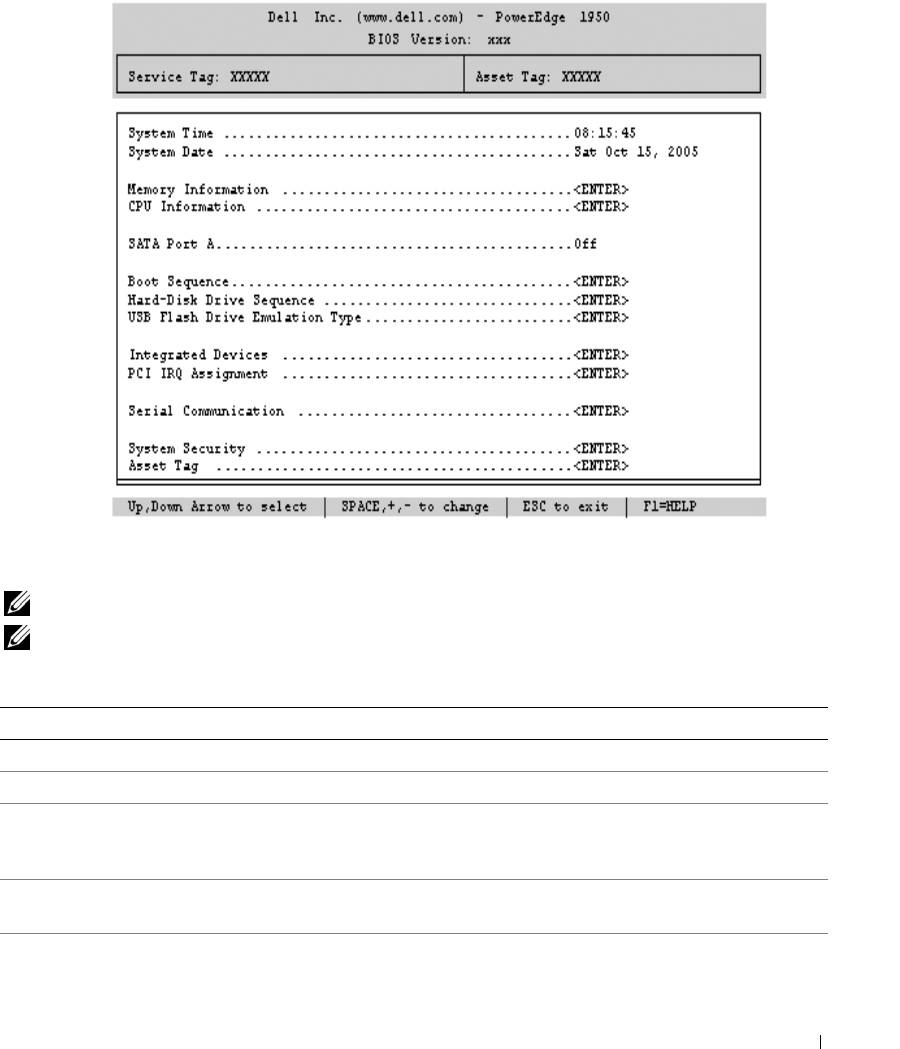
Figure 2-1. Main System Setup Program Screen
Table 2-2 lists the options and descriptions for the information fields that appear on the main System Setup
program screen. For related information, see "System Security Screen Options" on page 37.
NOTE: The options for the System Setup program change based on the system configuration.
NOTE: The System Setup program defaults are listed under their respective options, where applicable.
Table 2-2. System Setup Program Options
Option Description
System Time Resets the time on the system's internal clock.
System Date Resets the date on the system's internal calendar.
Memory Information Displays information related to installed system, video, and redundant memory,
including size, type, and speed of memory modules, system memory test option
status, and redundant memory status.
CPU Information Displays information related to microprocessors (speed, cache size, and so on). See
"CPU Information Screen" on page 35."
SATA Port x Displays type and capacity of drive attached to port x.
Using the System Setup Program 33

Table 2-2. System Setup Program Options (continued)
Option Description
Boot Sequence Determines the order in which the system searches for boot devices during system
startup. Available options can include the diskette drive, CD drive, hard drives, and
network. If you have installed a RAC, additional options, such as virtual floppy and
virtual CD-ROM, may be present.
NOTE: System boot is not supported from an external device attached to a SAS or
SCSI adapter. See support.dell.com for the latest support information about booting
from external devices.
USB Flash Drive Type
Determines the emulation type for a USB flash drive. Hard disk allows the USB flash
(
Auto
default)
drive to act as a hard drive. Floppy allows the USB flash drive to act as a removal
diskette drive. Auto automatically chooses an emulation type.
Integrated Devices See "Integrated Devices Screen" on page 36.
PCI IRQ Assignment Displays a screen to change the IRQ assigned to each of the integrated devices on the
PCI bus, and any installed expansion cards that require an IRQ.
Serial Communication
Options are On with Console Redirection via COM2, and Off.
(Off default)
Failsafe Baud Rate
Displays the failsafe baud rate used for console redirection when the baud rate cannot
(57600 default)
be negotiated automatically with the remote terminal. This rate should not be
adjusted.
Remote Terminal Type
Select either VT 100/VT 220 or ANSI.
(VT 100/VT 220 default)
Redirection After Boot
Enables or disables BIOS console redirection after your system boots to the operating
(Enabled default)
system.
Embedded Server
Displays a screen to configure the front-panel LCD options and to set a user-defined
Management
LCD string. For more information, see the systems management software
documentation that describes the features, requirements, installation, and basic
operation of the embedded software.
System Security Displays a screen to configure the system password and setup password features. See
"System Security Screen" on page 37, "Using the System Password" on page 38, and
"Using the Setup Password" on page 40 for more information.
Keyboard NumLock
Determines whether your system starts up with the NumLock mode activated on 101-
(
On
default)
or 102-key keyboards (does not apply to 84-key keyboards).
Report Keyboard Errors
Enables or disables reporting of keyboard errors during the POST. Select Report for
(
Report
default)
host systems that have keyboards attached. Select Do Not Report to suppress all error
messages relating to the keyboard or keyboard controller during POST. This setting
does not affect the operation of the keyboard itself if a keyboard is attached to the
system.
34 Using the System Setup Program

CPU Information Screen
Table 2-3 lists the options and descriptions for the information fields that appear on the CPU Information
screen.
Table 2-3. CPU Information Screen
Option Description
Bus Speed Displays the bus speed of the processors.
Logical Processor
Displays when the processors support HyperThreading. Enabled
(Enabled default)
permits all logical processors to be used by the operating system.
Only the first logical processor of each processor installed in the
system is used by the operating system if Disabled is selected.
Virtualization Technology
Displays when the processor(s) support Virtualization Technology.
Enabled permits virtualization software to utilize Virtualization
(Disabled default)
Technology functions incorporated in the processor design. This
feature can only be used by software that supports Virtualization
Technology.
Adjacent Cache Line
Enables or disables optimal use of sequential memory access. Disable
Prefetch
this option for applications that require high use of random memory
(Enabled default)
access.
Hardware Prefetcher
Enables or disables the hardware prefetcher.
(Enabled default)
Demand-Based Power
Enables or disables demand-based power management. When
Management
enabled, the CPU Performance State tables will be reported to the
(Disabled default)
operating system; when disabled, the CPU Performance State tables
will not be reported to the operating system. If any of the CPUs do not
support demand-based power management, the field will become
read-only, and automatically set to Disabled.
Processor X ID Displays the family and model number of each processor. A submenu
displays processor and core speed, amount of level 2 cache, and the
number of cores.
Using the System Setup Program 35

Integrated Devices Screen
Table 2-4 lists the options and descriptions for the information fields that appear on the Integrated Devices
screen.
Table 2-4. Integrated Devices Screen Options
Option Description
Integrated SAS Controller
Enables or disables the integrated SAS controller.
(Enabled default)
Embedded SATA
Allows the integrated SATA controller to be set to Off or ATA mode.
Controller
(Off default)
IDE CD-ROM Controller
Enables the integrated IDE controller. When set to
Auto
, each channel of the integrated
(Auto default)
IDE controller is enabled if IDE devices are attached to the channel and an external IDE
controller is not detected.
NOTE: This CD-ROM option will not appear on this menu screen if your system
does not include this optional device.
User-Accessible USB Ports
Enables or disables the system's user-accessible ports. Options are All Ports On,
(All Ports On default)
Only Back Ports On, or All Ports Off. Disabling the USB ports makes system
resources available for other devices.
Embedded Gb NIC1
Enables or disables the system's integrated NIC1. Options are Enabled without PXE,
(Enabled with PXE
Enabled with PXE, and Disabled. PXE support allows the system to boot from the
default)
network. Changes take effect after the system reboots.
MAC Address Displays the MAC address for NIC1. This field does not have user-selectable settings.
TOE Capability Displays the TCP/IP Offload Engine (TOE) feature status of NIC1.
Embedded Gb NIC2
Enables or disables the system's integrated NIC2. Options are Enabled without PXE,
(Enabled without PXE
Enabled with PXE, and Disabled. PXE support allows the system to boot from the
default)
network. Changes take effect after the system reboots.
MAC Address Displays the MAC address for NIC2. This field does not have user-selectable settings.
TOE Capability Displays the TCP/IP Offload Engine (TOE) feature status of NIC2.
36 Using the System Setup Program

System Security Screen
Table 2-5 lists the options and descriptions for the information fields that appear on the System Security
screen.
Table 2-5. System Security Screen Options
Option Description
System Password Displays the current status of your system's password security feature and allows you
to assign and verify a new system password.
NOTE: See "Using the System Password" on page 38 for instructions on assigning a
system password and using or changing an existing system password.
Setup Password Restricts access to the System Setup program in the same way that you restrict access
to your system using the system password feature.
NOTE: See "Using the Setup Password" on page 40 for instructions on assigning a
setup password and using or changing an existing setup password.
Password Status Setting the Setup Password option to Enabled prevents the system password from
being changed or disabled at system start-up.
To lock the system password, assign a setup password in the Setup Password option
and then change the Password Status option to Locked. In this state, you cannot
change the system password using the System Password option and cannot be
disabled at system start-up by pressing <Ctrl><Enter>.
To unlock the system password, enter the setup password in the Setup Password field
and then change the Password Status option to Unlocked. In this state, you can
disable the system password at system start-up by pressing <Ctrl><Enter> and then
change the password using the System Password option.
Power Button
Turns system's power off and on.
• If you turn off the system using the power button and the system is running an ACPI-
compliant operating system, the system can perform an orderly shutdown before
power is turned off.
• If the system is not running an ACPI-compliant operating system, power is turned off
immediately after the power button is pressed.
The button is enabled in the System Setup program. When disabled, the button can
only turn on system power.
NOTE: You can still turn on the system by using the power button, even if the Power
Button option is set to Disabled.
NMI Button NOTICE: Use the NMI button only if directed to do so by qualified support
personnel or by the operating system's documentation. Pressing this button halts
the operating system and displays a diagnostic screen.
Enables or disables the NMI feature.
Using the System Setup Program 37

Table 2-5. System Security Screen Options (continued)
Option Description
AC Power Recovery
Determines how the system reacts when power is restored to the system. If system is
(Last default)
set to Last, the system returns to the last power state. On turns on the system after
power is restored. When set to Off, the system remains off after power is restored.
Exit Screen
After you press <Esc> to exit the System Setup program, the Exit screen displays the following options:
•
Save Changes and Exit
• Discard Changes and Exit
• Return to Setup
System and Setup Password Features
NOTICE: The password features provide a basic level of security for the data on your system. If your data
requires more security, use additional forms of protection, such as data encryption programs.
NOTICE: Anyone can access the data stored on your system if you leave the system running and unattended
without having a system password assigned or if you leave your system unlocked so that someone can disable the
password by changing a jumper setting.
Your system is shipped to you without the system password feature enabled. If system security is a concern,
operate your system only with system password protection.
To change or delete an existing password, you must know the password (see "Deleting or Changing an
Existing System Password" on page 40). If you forget your password, you cannot operate your system or
change settings in the System Setup program until a trained service technician changes the password jumper
setting to disable the passwords, and erases the existing passwords. This procedure is described in
"Disabling a Forgotten Password" on page 117.
Using the System Password
After a system password is assigned, only those who know the password have full use of the system. When
the System Password option is set to Enabled, the system prompts you for the system password after the
system starts.
Assigning a System Password
Before you assign a system password, enter the System Setup program and check the System Password
option.
38 Using the System Setup Program

When a system password is assigned, the setting shown for the System Password option is Enabled. If the
setting shown for the Password Status is Unlocked, you can change the system password. If the Password
Status option is Locked, you cannot change the system password. When the system password feature is
disabled by a jumper setting, the system password is Disabled, and you cannot change or enter a new system
password.
When a system password is not assigned and the password jumper on the system board is in the enabled
(default) position, the setting shown for the System Password option is Not Enabled and the Password
Status field is Unlocked. To assign a system password:
1
Verify that the
Password Status
option is set to
Unlocked
.
2
Highlight the
System Password
option and press <Enter>.
3
Type your new system password.
You can use up to 32 characters in your password.
As you press each character key (or the spacebar for a blank space), a placeholder appears in the field.
The password assignment is not case-sensitive. However, certain key combinations are not valid. To erase
a character when entering your password, press <Backspace> or the left-arrow key.
NOTE: To escape from the field without assigning a system password, press <Enter> to move to another
field, or press <Esc> at any time prior to completing step 5.
4
Press <Enter>.
5
To confirm your password, type it a second time and press <Enter>.
The setting shown for the
System Password
changes to
Enabled
. Exit the System Setup program and
begin using your system.
6
Either reboot your system now for your password protection to take effect or continue working.
NOTE: Password protection does not take effect until you reboot the system.
Using Your System Password to Secure Your System
NOTE: If you have assigned a setup password (see "Using the Setup Password" on page 40"), the system accepts
your setup password as an alternate system password.
When the Password Status option is set to Unlocked, you have the option to leave the password security
enabled or to disable the password security.
To leave the password security enabled:
1
Turn on or reboot your system by pressing <Ctrl><Alt><Del>.
2
Type your password and press <Enter>.
To disable the password security:
1
Turn on or reboot your system by pressing <Ctrl><Alt><Del>.
2
Type your password and press <Ctrl><Enter>.
Using the System Setup Program 39

When the Password Status option is set to Locked whenever you turn on your system or reboot your
system by pressing <Ctrl><Alt><Del>, type your password and press <Enter> at the prompt.
After you type the correct system password and press <Enter>, your system operates as usual.
If an incorrect system password is entered, the system displays a message and prompts you to re-enter your
password. You have three attempts to enter the correct password. After the third unsuccessful attempt, the
system displays an error message showing the number of unsuccessful attempts and that the system has
halted and will shut down. This message can alert you to an unauthorized person attempting to use your
system.
Even after you shut down and restart the system, the error message continues to be displayed until the
correct password is entered.
NOTE: You can use the Password Status option in conjunction with the System Password and Setup Password
options to further protect your system from unauthorized changes.
Deleting or Changing an Existing System Password
1
When prompted, press <Ctrl><Enter> to disable the existing system password.
If you are asked to enter your setup password, contact your network administrator.
2
Enter the System Setup program by pressing <F2> during POST.
3
Select the
System Security
screen field to verify that the
Password Status
option is set to
Unlocked
.
4
When prompted, type the system password.
5
Confirm that
Not Enabled
is displayed for the
System Password
option.
If
Not Enabled
is displayed for the
System Password
option, the system password has been deleted. If
Enabled
is displayed for the
System Password
option, press the <Alt><b> key combination to restart the
system, and then repeat steps 2 through 5.
Using the Setup Password
Read the information in the following sections to assign or change your setup password.
Assigning a Setup Password
You can assign (or change) a setup password only when the Setup Password option is set to Not Enabled.
To assign a setup password, highlight the Setup Password option and press the <+> or <–> key. The system
prompts you to enter and verify the password. If a character is illegal for password use, the system beeps.
NOTE: The setup password can be the same as the system password. If the two passwords are different, the setup
password can be used as an alternate system password. However, the system password cannot be used in place of
the setup password.
You can use up to 32 characters in your password.
As you press each character key (or the spacebar for a blank space), a placeholder appears in the field.
40 Using the System Setup Program
