Asus M4A785D-M PRO: 1.5 Motherboard overview
1.5 Motherboard overview: Asus M4A785D-M PRO
ASUS M4A785D-M PRO 1-5
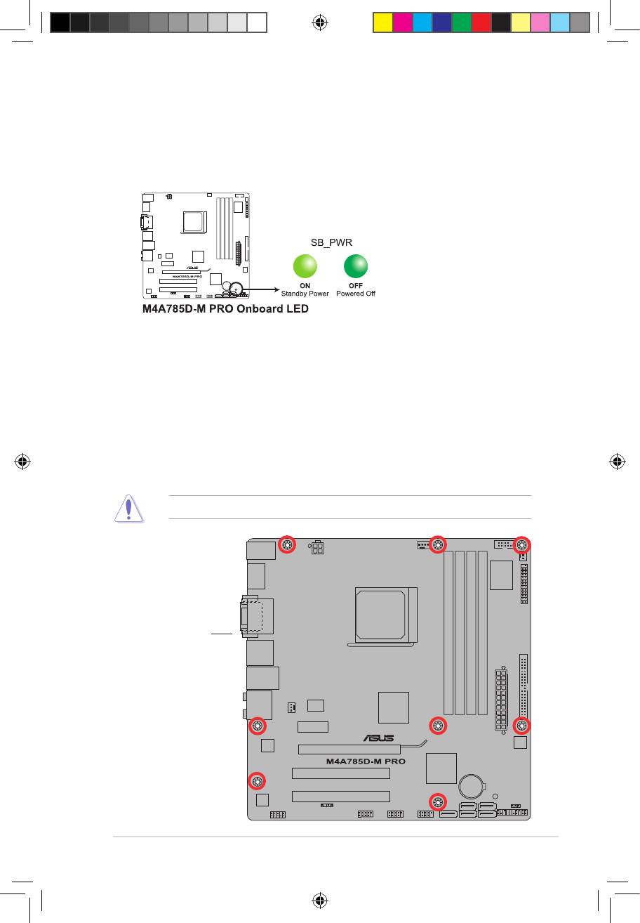
Onboard LED
The motherboard comes with a standby power LED that lights up to indicate that the system
is ON, in sleep mode, or in soft-off mode. This is a reminder that you should shut down
the system and unplug the power cable before removing or plugging in any motherboard
component. The illustration below shows the location of the onboard LED.
1.5 Motherboard overview
1.5.1 Placement direction
When installing the motherboard, ensure that you place it into the chassis in the correct
orientation. The edge with external ports goes to the rear part of the chassis as indicated in
the image below.
1.5.2 Screw holes
Place eight screws into the holes indicated by circles to secure the motherboard to the
chassis.
Do not overtighten the screws! Doing so can damage the motherboard.
Place this side towards
the rear of the chassis.
E4711_M4A785D-M PRO.indb 5 7/6/09 9:09:36 AM
1-6 Chapter 1: Product introduction
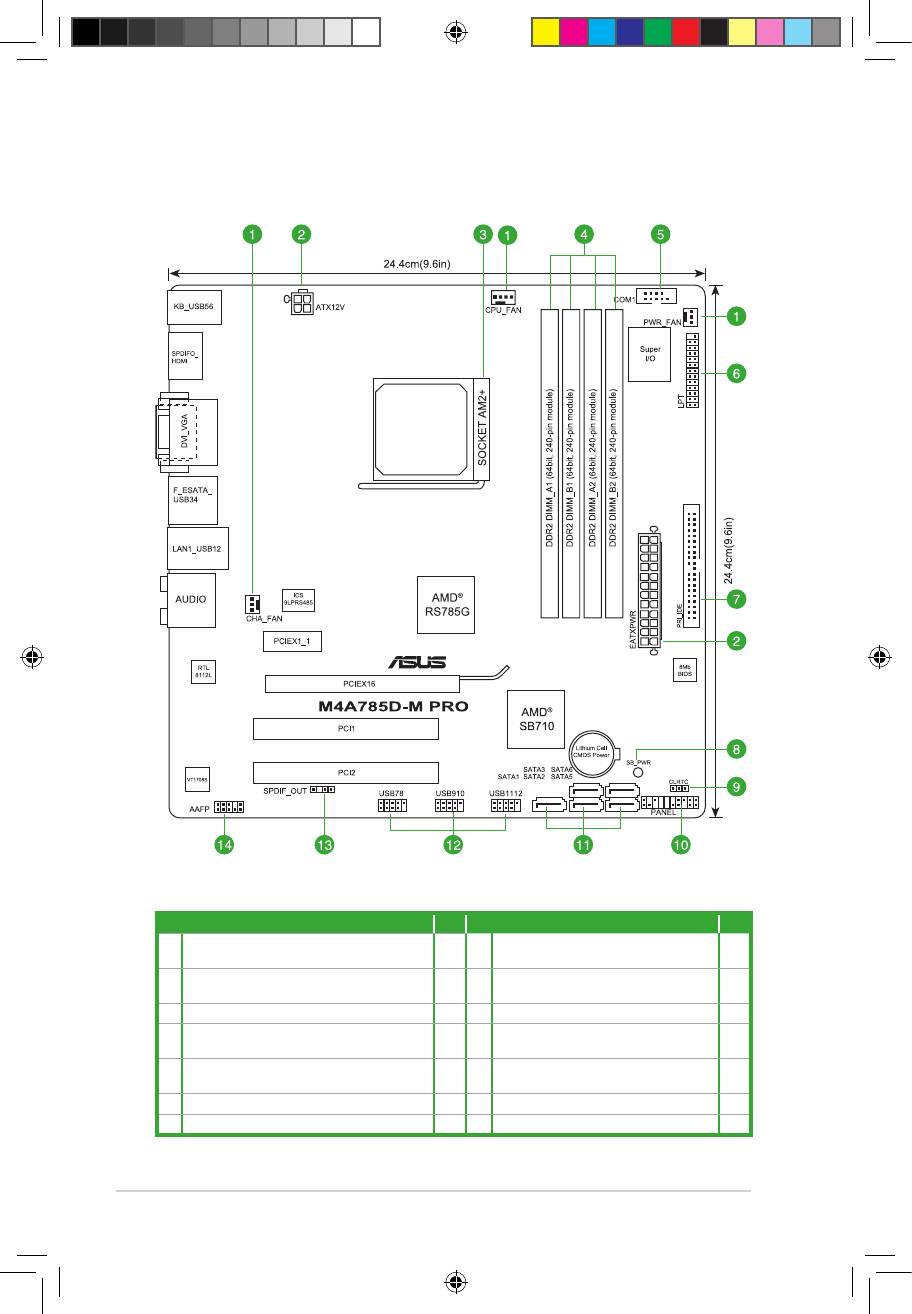
1.5.3 Motherboard layout
1.5.4 Layout contents
Connectors/Jumpers/Slots Page Connectors/Jumpers/Slots Page
1. CPU, chassis, and power fan connectors (4-pin
1-29 8. Onboard LED 1-5
CPU_FAN, 3-pin CHA_FAN, 3-pin PWR_FAN)
2. ATX power connectors (24-pin EATXPWR, 4-pin
1-24 9. Clear RTC RAM (CLRTC) 1-20
ATX12V)
3. AMD CPU socket 1-7 10. System panel connector (20-8 pin PANEL) 1-27
4. DDR2 DIMM sockets 1-10 11. Serial ATA connectors (7-pin SATA1, SATA2,
1-26
SATA3, SATA5, SATA6)
5. Serial port connectors (10-1 pin COM1) 1-29 12. USB connectors (10-1 pin USB78, USB910,
1-28
USB1112)
6. LPT connector (26-1 pin LPT) 1-26 13. Digital audio connector (4-1 pin SPDIF_OUT) 1-25
7. IDE connector (40-1 pin PRI_IDE) 1-25 14. Front panel audio connector (10-1 pin AAFP) 1-28
E4711_M4A785D-M PRO.indb 6 7/6/09 9:09:37 AM
Оглавление
- Contents
- Notices
- Safety information
- About this guide
- M4A785D-M PRO specications summary
- 1.1 Welcome!
- 1.4 Before you proceed
- 1.5 Motherboard overview
- 1.6 Central Processing Unit (CPU)
- 1.7 System memory
- 1.8 Expansion slots
- 1.9 Jumpers
- 1.10 Connectors
- 1.11 Software support
- 2.1 Managing and updating your BIOS
- 2.2 BIOS setup program
- 2.3 Main menu
- 2.4 Advanced menu
- 2.5 Power menu
- 2.6 Boot menu
- 2.7 Tools menu
- 2.8 Exit menu
