Pioneer DEH-6400BT: Removing the unit DIN front/rear mount
Removing the unit DIN front/rear mount: Pioneer DEH-6400BT
Table of contents
Important
! Check all connections and systems before
final installation.
! Do not use unauthorized parts as this may
cause malfunctions.
! Consult your dealer if installation requires
drilling of holes or other modifications to the
vehicle.
! Do not install this unit where:
— it may interfere with operation of the vehicle.
— it may cause injury to a passenger as a result
of a sudden stop.
! The semiconductor laser will be damaged if
it overheats. Install this unit away from hot
places such as near the heater outlet.
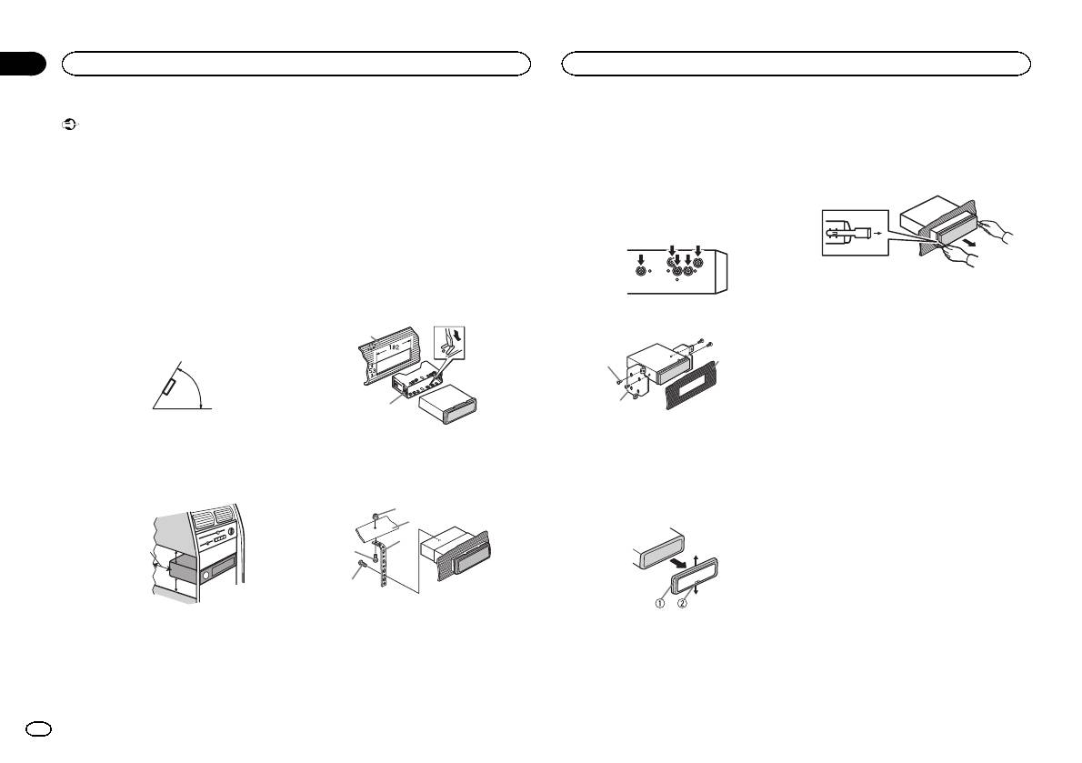
! Optimum performance is obtained when the
unit is installed at an angle of less than 60°.
60°
! When installing, to ensure proper heat dis-
persal when using this unit, make sure you
leave ample space behind the rear panel and
wrap any loose cables so they are not block-
ing the vents.
5cmcm
Section
01
Installation
Installation
Use commercially available parts when instal-
# Make sure that the unit is installed securely in
2 Insert the supplied extraction keys into
ling.
place. An unstable installation may cause skipping
both sides of the unit until they click into
or other malfunctions.
place.
DIN Front-mount
DIN Rear-mount
3 Pull the unit out of the dashboard.
1 Insert the mounting sleeve into the dash-
board.
1 Determine the appropriate position
For installation in shallow spaces, use the sup-
where the holes on the bracket and the side
plied mounting sleeve. If there is enough space,
of the unit match.
use the mounting sleeve that came with the ve-
hicle.
2 Secure the mounting sleeve by using a
screwdriver to bend the metal tabs (90°) into
Removing and re-attaching the
place.
front panel
2 Tighten two screws on each side.
You can remove the front panel to protect your
1
unit from theft.
3
Press the detach button and push the front
1
panel upward and pull it toward you.
For details, refer to operation manual.
2
2
1 Tapping screw (5 mm × 8 mm)
1 Dashboard
2 Mounting bracket
2 Mounting sleeve
3 Dashboard or console
3 Install the unit as illustrated.
Removing the unit
1
1 Remove the trim ring.
2
3
Leave ample
4
5 cm
space
5 cm
5
1 Nut
2 Firewall or metal support
1 Trim ring
3 Metal strap
2 Notched tab
DIN front/rear mount
4 Screw
! Releasing the front panel allows easier ac-
5 Screw (M4 × 8)
cess to the trim ring.
This unit can be properly installed using either
! When reattaching the trim ring, point the
front-mount or rear-mount installation.
side with the notched tab down.
2
En
