Pioneer DEH-141UB: Installation DIN front/rear mount
Installation DIN front/rear mount: Pioneer DEH-141UB
Table of contents
- About this unit About this manual Demo mode In case of trouble
- Head unit Display indication Basic operations Set up menu
- Tuner Menu operations identical for set up menu/function settings/audio adjustments/ initial settings/lists
- CD/CD-R/CD-RW and USB storage devices
- Initial settings Audio adjustments
- Connections Turning the clock display on or off Sound muting Using an AUX source
- Installation DIN front/rear mount
- Troubleshooting Error messages
- Handling guidelines
- Compressed audio compatibility (disc, USB) WMA Sequence of audio files
- Specifications WMA Russian character chart Copyright and trademark
3 Antenna input
4 Fuse (10 A)
5 Wired remote input
Hard-wired remote control adaptor can be
connected (sold separately).
Power cord
3
4
1
2
5
6
3
4
7
5
6
8
a
9
b
e
d
8 Black (chassis ground)
1 System remote control
! When installing, to ensure proper heat dis-
9 Blue/white
Connect to Blue/white cable.
persal when using this unit, make sure you
The pin position of the ISO connector will dif-
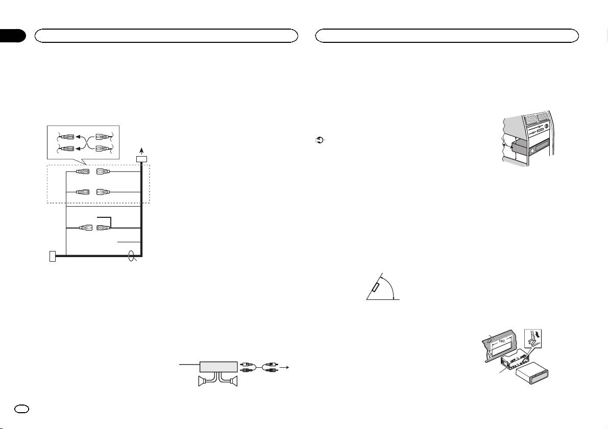
2 Power amp (sold separately)
leave ample space behind the rear panel and
fer depending on the type of vehicle. Connect
3 Connect with RCA cables (sold separately)
wrap any loose cables so they are not block-
9 and b when Pin 5 is an antenna control
4 To Rear output
ing the vents.
type. In another type of vehicle, never con-
5 Rear speaker
nect 9 and b.
a Blue/white
Connect to system control terminal of the
Installation
power amp (max. 300 mA 12 V DC).
Important
b Blue/white
! Check all connections and systems before
Connect to auto-antenna relay control termi-
final installation.
nal (max. 300 mA 12 V DC).
! Do not use unauthorized parts as this may
c Yellow/black
cause malfunctions.
Only for DEH-142UB, DEH-140UB and DEH-
! Consult your dealer if installation requires
140UBB.
drilling of holes or other modifications to the
If you use an equipment with Mute function,
vehicle.
wire this lead to the Audio Mute lead on that
! Do not install this unit where:
equipment. If not, keep the Audio Mute lead
— it may interfere with operation of the vehicle.
free of any connections.
— it may cause injury to a passenger as a result
d Speaker leads
of a sudden stop.
White: Front left +
! The semiconductor laser will be damaged if
White/black: Front left *
it overheats. Install this unit away from hot
c
Gray: Front right +
places such as near the heater outlet.
Gray/black: Front right *
! Optimum performance is obtained when the
Green: Rear left +
unit is installed at an angle of less than 60°.
Green/black: Rear left *
1 To power cord input
Violet: Rear right +
2 Depending on the kind of vehicle, the func-
Violet/black: Rear right *
60°
tion of 3 and 5 may be different. In this
e ISO connector
case, be sure to connect 4 to 5 and 6 to
In some vehicles, the ISO connector may be
3.
divided into two. In this case, be sure to con-
3 Yellow
nect to both connectors.
Back-up (or accessory)
4 Yellow
Power amp (sold separately)
Connect to the constant 12 V supply termi-
Perform these connections when using the op-
nal.
tional amplifier.
5 Red
Accessory (or back-up)
1
3
6 Red
2
Connect to terminal controlled by ignition
4
switch (12 V DC).
55
7 Connect leads of the same color to each
other.
5cmcm
Section
03
Installation
Installation
Leave ample
5 cm
space
5 cm
DIN front/rear mount
This unit can be properly installed using either
front-mount or rear-mount installation.
Use commercially available parts when instal-
ling.
DIN Front-mount
1 Insert the mounting sleeve into the dash-
board.
For installation in shallow spaces, use the sup-
plied mounting sleeve. If there is enough space,
use the mounting sleeve that came with the ve-
hicle.
2 Secure the mounting sleeve by using a
screwdriver to bend the metal tabs (90°) into
place.
1
2
1 Dashboard
8
En
