Dell PowerVault MD3600i: инструкция
Раздел: Бытовая, кухонная техника, электроника и оборудование
Тип: Компьютерные аксессуары
Инструкция к Компьютерным аксессуарам Dell PowerVault MD3600i
Оглавление
Dell™ XPS 600
Owner’s Manual
Model WHL
www.dell.com | support.dell.com

Notes, Notices, and Cautions
NOTE: A NOTE indicates important information that helps you make better use of your computer.
NOTICE: A NOTICE indicates either potential damage to hardware or loss of data and tells you how to avoid the
problem.
CAUTION: A CAUTION indicates a potential for property damage, personal injury, or death.
®
®
If you purchased a Dell™ n Series computer, any references in this document to Microsoft
Windows
operating systems are not applicable.
____________________
Information in this document is subject to change without notice.
© 2005 Dell Inc. All rights reserved.
Reproduction in any manner whatsoever without the written permission of Dell Inc. is strictly forbidden.
Trademarks used in this text: Dell, the DELL logo, Inspiron, Dell Precision, Dimension, OptiPlex, Latitude, PowerEdge, PowerVault, and
PowerApp are trademarks of Dell Inc.; Intel and Pentium are registered trademarks of Intel Corporation; Microsoft and Windows are registered
trademarks of Microsoft Corporation.
Other trademarks and trade names may be used in this document to refer to either the entities claiming the marks and names or their products.
Dell Inc. disclaims any proprietary interest in trademarks and trade names other than its own.
Model WHL
November 2005 P/N HC098 Rev. A03

Contents
Finding Information . . . . . . . . . . . . . . . . . . . . . . . . . . . . . . . . 9
1 Setting Up and Using Your Computer
Opening the Drive Door . . . . . . . . . . . . . . . . . . . . . . . . . . . . . 15
Changing the Front-Panel Light Color
. . . . . . . . . . . . . . . . . . . . . . 15
Using a Media Card Reader (Optional)
. . . . . . . . . . . . . . . . . . . . . 17
Connecting Monitors
. . . . . . . . . . . . . . . . . . . . . . . . . . . . . . . 18
Connecting a Monitor to a PCI Express Graphics Card
Dual Configuration
. . . . . . . . . . . . . . . . . . . . . . . . . . . . . 18
Connecting Two Monitors
. . . . . . . . . . . . . . . . . . . . . . . . . 18
Connecting a TV
. . . . . . . . . . . . . . . . . . . . . . . . . . . . . . 20
Changing the Display Settings to Support Two Monitors
. . . . . . . . . 20
About Serial ATA Drives
. . . . . . . . . . . . . . . . . . . . . . . . . . . . . 21
About Your RAID Configuration
. . . . . . . . . . . . . . . . . . . . . . . . . 21
RAID Level 0 Configuration
. . . . . . . . . . . . . . . . . . . . . . . . . 21
RAID Level 1 Configuration
. . . . . . . . . . . . . . . . . . . . . . . . . 22
Configuring Your Hard Drives for RAID
. . . . . . . . . . . . . . . . . . . 23
Creating an Array using the Nvidia MediaShield ROM Utility
. . . . . . . 23
Using Nvidia MediaShield
. . . . . . . . . . . . . . . . . . . . . . . . . 24
Transferring Information to a New Computer
. . . . . . . . . . . . . . . . . . 27
Playing CDs and DVDs
. . . . . . . . . . . . . . . . . . . . . . . . . . . . . . 28
Playing a CD or DVD
. . . . . . . . . . . . . . . . . . . . . . . . . . . . 28
Adjusting the Volume
. . . . . . . . . . . . . . . . . . . . . . . . . . . . 29
Adjusting the Picture
. . . . . . . . . . . . . . . . . . . . . . . . . . . . 30
Copying CDs and DVDs
. . . . . . . . . . . . . . . . . . . . . . . . . . . . . . 30
How to Copy a CD or DVD
. . . . . . . . . . . . . . . . . . . . . . . . . . 30
Using Blank CDs and DVDs
. . . . . . . . . . . . . . . . . . . . . . . . . 31
Helpful Tips
. . . . . . . . . . . . . . . . . . . . . . . . . . . . . . . . . 32
Network Setup Wizard
. . . . . . . . . . . . . . . . . . . . . . . . . . . . . . 32
Contents 3

Power Management . . . . . . . . . . . . . . . . . . . . . . . . . . . . . . . 33
Overview
. . . . . . . . . . . . . . . . . . . . . . . . . . . . . . . . . . 33
Standby Mode
. . . . . . . . . . . . . . . . . . . . . . . . . . . . . . . 33
Hibernate Mode
. . . . . . . . . . . . . . . . . . . . . . . . . . . . . . . 33
Power Options Properties
. . . . . . . . . . . . . . . . . . . . . . . . . 34
2 Optimizing Performance
Hyper-Threading . . . . . . . . . . . . . . . . . . . . . . . . . . . . . . . . . 37
PCI Express Cards
. . . . . . . . . . . . . . . . . . . . . . . . . . . . . . . . 37
NVIDIA SLI Dual Graphics Technology
. . . . . . . . . . . . . . . . . . . . . 38
3 Solving Problems
Troubleshooting Tips. . . . . . . . . . . . . . . . . . . . . . . . . . . . . . . 39
Battery Problems
. . . . . . . . . . . . . . . . . . . . . . . . . . . . . . . . . 39
Drive Problems
. . . . . . . . . . . . . . . . . . . . . . . . . . . . . . . . . . 39
CD and DVD drive problems
. . . . . . . . . . . . . . . . . . . . . . . . 40
Hard drive problems
. . . . . . . . . . . . . . . . . . . . . . . . . . . . 41
E-Mail, Modem, and Internet Problems
. . . . . . . . . . . . . . . . . . . . . 41
Error Messages
. . . . . . . . . . . . . . . . . . . . . . . . . . . . . . . . . 42
IEEE 1394 Device Problems
. . . . . . . . . . . . . . . . . . . . . . . . . . . 43
Keyboard Problems
. . . . . . . . . . . . . . . . . . . . . . . . . . . . . . . 44
Lockups and Software Problems
. . . . . . . . . . . . . . . . . . . . . . . . 44
The computer does not start up
. . . . . . . . . . . . . . . . . . . . . . 45
The computer stops responding
. . . . . . . . . . . . . . . . . . . . . . 45
A program stops responding
. . . . . . . . . . . . . . . . . . . . . . . . 45
A program crashes repeatedly
. . . . . . . . . . . . . . . . . . . . . . . 45
A program is designed for an earlier Windows operating system
. . . . . 46
A solid blue screen appears
. . . . . . . . . . . . . . . . . . . . . . . . 46
Other software problems
. . . . . . . . . . . . . . . . . . . . . . . . . . 46
Memory Problems
. . . . . . . . . . . . . . . . . . . . . . . . . . . . . . . . 47
Mouse Problems
. . . . . . . . . . . . . . . . . . . . . . . . . . . . . . . . . 47
4 Contents

Network Problems . . . . . . . . . . . . . . . . . . . . . . . . . . . . . . . . 48
Power Problems
. . . . . . . . . . . . . . . . . . . . . . . . . . . . . . . . . 49
Printer Problems
. . . . . . . . . . . . . . . . . . . . . . . . . . . . . . . . . 50
Scanner Problems
. . . . . . . . . . . . . . . . . . . . . . . . . . . . . . . . 51
Sound and Speaker Problems
. . . . . . . . . . . . . . . . . . . . . . . . . . 51
No sound from speakers
. . . . . . . . . . . . . . . . . . . . . . . . . . 51
No sound from headphones
. . . . . . . . . . . . . . . . . . . . . . . . 52
Video and Monitor Problems
. . . . . . . . . . . . . . . . . . . . . . . . . . 53
If the screen is blank
. . . . . . . . . . . . . . . . . . . . . . . . . . . . 53
If the screen is difficult to read
. . . . . . . . . . . . . . . . . . . . . . . 53
If 3-D image quality is poor
. . . . . . . . . . . . . . . . . . . . . . . . . 54
4 Advanced Troubleshooting
Diagnostic Lights. . . . . . . . . . . . . . . . . . . . . . . . . . . . . . . . . 55
Dell Diagnostics
. . . . . . . . . . . . . . . . . . . . . . . . . . . . . . . . . 58
When to Use the Dell Diagnostics
. . . . . . . . . . . . . . . . . . . . . 58
Drivers
. . . . . . . . . . . . . . . . . . . . . . . . . . . . . . . . . . . . . . 60
What Is a Driver?
. . . . . . . . . . . . . . . . . . . . . . . . . . . . . . 60
Identifying Drivers
. . . . . . . . . . . . . . . . . . . . . . . . . . . . . 60
Reinstalling Drivers
. . . . . . . . . . . . . . . . . . . . . . . . . . . . . 61
®
®
Using Microsoft
Windows
XP System Restore . . . . . . . . . . . . . . . 62
Creating a Restore Point
. . . . . . . . . . . . . . . . . . . . . . . . . . 63
Restoring the Computer to an Earlier Operating State
. . . . . . . . . . . 63
Undoing the Last System Restore
. . . . . . . . . . . . . . . . . . . . . . 63
Resolving Software and Hardware Incompatibilities
. . . . . . . . . . . . . 64
®
®
Reinstalling Microsoft
Windows
XP. . . . . . . . . . . . . . . . . . . . . 64
Before You Begin
. . . . . . . . . . . . . . . . . . . . . . . . . . . . . . 64
Reinstalling Windows XP
. . . . . . . . . . . . . . . . . . . . . . . . . . 65
Contents 5

5 Removing and Installing Parts
Before You Begin. . . . . . . . . . . . . . . . . . . . . . . . . . . . . . . . . 69
Recommended Tools
. . . . . . . . . . . . . . . . . . . . . . . . . . . . 69
Turning Off Your Computer
. . . . . . . . . . . . . . . . . . . . . . . . . 69
Before Working Inside Your Computer
. . . . . . . . . . . . . . . . . . . 70
Front and Back View of the Computer
. . . . . . . . . . . . . . . . . . . . . . 71
Front View
. . . . . . . . . . . . . . . . . . . . . . . . . . . . . . . . . . 71
Front View (Doors Open)
. . . . . . . . . . . . . . . . . . . . . . . . . . 72
Back View
. . . . . . . . . . . . . . . . . . . . . . . . . . . . . . . . . . 73
Opening the Computer Cover
. . . . . . . . . . . . . . . . . . . . . . . . . . 76
Inside View of Your Computer
. . . . . . . . . . . . . . . . . . . . . . . . . . 77
System Board Components
. . . . . . . . . . . . . . . . . . . . . . . . . . . . 78
Memory
. . . . . . . . . . . . . . . . . . . . . . . . . . . . . . . . . . . . . . 79
Addressing Memory Configurations
. . . . . . . . . . . . . . . . . . . . 80
Installing Memory
. . . . . . . . . . . . . . . . . . . . . . . . . . . . . . 80
Removing Memory
. . . . . . . . . . . . . . . . . . . . . . . . . . . . . 82
Cards
. . . . . . . . . . . . . . . . . . . . . . . . . . . . . . . . . . . . . . . 82
Removing a PCI Express Graphics Card from a Dual Configuration
. . . . 84
Installing PCI Express Graphics Cards in a Dual Configuration
. . . . . . 86
Removing PCI and PCI Express Cards
. . . . . . . . . . . . . . . . . . . 89
Installing PCI and PCI Express Cards
. . . . . . . . . . . . . . . . . . . . 91
Network Adapter and Sound Card Settings
. . . . . . . . . . . . . . . . 94
Drives
. . . . . . . . . . . . . . . . . . . . . . . . . . . . . . . . . . . . . . . 95
General Installation Guidelines
. . . . . . . . . . . . . . . . . . . . . . . 95
Connecting Drive Cables
. . . . . . . . . . . . . . . . . . . . . . . . . . 96
Hard Drive
. . . . . . . . . . . . . . . . . . . . . . . . . . . . . . . . . . . . 97
Removing a Hard Drive
. . . . . . . . . . . . . . . . . . . . . . . . . . . 97
Installing a Hard Drive
. . . . . . . . . . . . . . . . . . . . . . . . . . . 98
Floppy Drive
. . . . . . . . . . . . . . . . . . . . . . . . . . . . . . . . . . 101
Removing a Floppy Drive
. . . . . . . . . . . . . . . . . . . . . . . . . 101
Installing a Floppy Drive
. . . . . . . . . . . . . . . . . . . . . . . . . 103
Media Card Reader
. . . . . . . . . . . . . . . . . . . . . . . . . . . . . . 105
Removing a Media Card Reader
. . . . . . . . . . . . . . . . . . . . . 105
Installing a Media Card Reader
. . . . . . . . . . . . . . . . . . . . . . 106
6 Contents

CD/DVD Drive. . . . . . . . . . . . . . . . . . . . . . . . . . . . . . . . . . 108
Removing a CD/DVD Drive
. . . . . . . . . . . . . . . . . . . . . . . . 109
Installing a CD/DVD Drive
. . . . . . . . . . . . . . . . . . . . . . . . . 110
Processor Airflow Shroud
. . . . . . . . . . . . . . . . . . . . . . . . . . . 112
Removing the Processor Airflow Shroud
. . . . . . . . . . . . . . . . . 112
Installing the Processor Airflow Shroud
. . . . . . . . . . . . . . . . . 113
Processor
. . . . . . . . . . . . . . . . . . . . . . . . . . . . . . . . . . . . 113
Removing the Processor
. . . . . . . . . . . . . . . . . . . . . . . . . 113
Installing the Processor
. . . . . . . . . . . . . . . . . . . . . . . . . 117
Front Panel
. . . . . . . . . . . . . . . . . . . . . . . . . . . . . . . . . . . 120
Removing the Front Panel
. . . . . . . . . . . . . . . . . . . . . . . . . 120
Replacing the Front Panel
. . . . . . . . . . . . . . . . . . . . . . . . 120
Drive Door
. . . . . . . . . . . . . . . . . . . . . . . . . . . . . . . . . . . 121
Removing the Drive Door
. . . . . . . . . . . . . . . . . . . . . . . . . 121
Replacing the Drive Door
. . . . . . . . . . . . . . . . . . . . . . . . . 122
Battery
. . . . . . . . . . . . . . . . . . . . . . . . . . . . . . . . . . . . . 124
Replacing the Battery
. . . . . . . . . . . . . . . . . . . . . . . . . . . 124
Closing the Computer Cover
. . . . . . . . . . . . . . . . . . . . . . . . . . 125
6 Appendix
Specifications . . . . . . . . . . . . . . . . . . . . . . . . . . . . . . . . . 127
System Setup
. . . . . . . . . . . . . . . . . . . . . . . . . . . . . . . . . . 131
Overview
. . . . . . . . . . . . . . . . . . . . . . . . . . . . . . . . . 131
Entering System Setup
. . . . . . . . . . . . . . . . . . . . . . . . . . 131
System Setup Options
. . . . . . . . . . . . . . . . . . . . . . . . . . . 132
Boot Sequence
. . . . . . . . . . . . . . . . . . . . . . . . . . . . . . 136
Clearing Forgotten Passwords
. . . . . . . . . . . . . . . . . . . . . . . . . 137
Clearing CMOS Settings
. . . . . . . . . . . . . . . . . . . . . . . . . . . . 138
Cleaning Your Computer
. . . . . . . . . . . . . . . . . . . . . . . . . . . . 139
Computer, Keyboard, and Monitor
. . . . . . . . . . . . . . . . . . . . 139
Mouse
. . . . . . . . . . . . . . . . . . . . . . . . . . . . . . . . . . . 139
Floppy Drive
. . . . . . . . . . . . . . . . . . . . . . . . . . . . . . . . 139
CDs and DVDs
. . . . . . . . . . . . . . . . . . . . . . . . . . . . . . . 140
Contents 7

Dell Technical Support Policy (U.S. Only) . . . . . . . . . . . . . . . . . . . 140
Definition of "Dell-Installed" Software and Peripherals
. . . . . . . . . 140
Definition of "Third-Party" Software and Peripherals
. . . . . . . . . . . 141
FCC Notices (U.S. Only)
. . . . . . . . . . . . . . . . . . . . . . . . . . . . 141
Class A
. . . . . . . . . . . . . . . . . . . . . . . . . . . . . . . . . . 141
Class B
. . . . . . . . . . . . . . . . . . . . . . . . . . . . . . . . . . 142
FCC Identification Information
. . . . . . . . . . . . . . . . . . . . . . 142
Contacting Dell
. . . . . . . . . . . . . . . . . . . . . . . . . . . . . . . . . 142
Index . . . . . . . . . . . . . . . . . . . . . . . . . . . . . . . . . . . . . . . . 161
8 Contents
Finding Information
NOTE: Some features or media may be optional and may not ship with your computer. Some features or
media may not be available in certain countries.
NOTE: Additional information may ship with your computer.
What Are You Looking For? Find It Here
• A diagnostic program for my computer
Drivers and Utilities CD (also known as ResourceCD)
• Drivers for my computer
Documentation and drivers are already installed on your
• My device documentation
computer. You can use the CD to reinstall drivers or to run
• Desktop System Software (DSS)
the Dell Diagnostics.
Readme files may be
included on your CD to
provide last-minute
updates about technical
changes to your computer
or advanced technical-
reference material for
technicians or experienced
users.
NOTE: Drivers and documentation updates can be found at
support.dell.com.
NOTE: The Drivers and Utilities CD is optional and may not
ship with your computer.
• How to set up my computer
Owner’s Manual
• Basic troubleshooting information
• How to run the Dell Diagnostics
• How to set up a printer
• Additional information about setting up my computer
• How to troubleshoot and solve problems
• How to remove and install parts
• Specifications
• How to contact Dell
NOTE: This document is available as a PDF at
support.dell.com.
Finding Information 9
What Are You Looking For? Find It Here
• Warranty information
Dell™ Product Information Guide
• Terms and Conditions (U.S. and Canada)
• Safety instructions
• Regulatory information
• Ergonomics information
• End User License Agreement
www.dell.com | support.dell.com
• How to set up my computer
Setup Diagram
10 Finding Information
What Are You Looking For? Find It Here
®
®
• Service Tag and Express Service Code
Service Tag and Microsoft
Windows
License
• Microsoft Windows License Label
These labels are located on your computer.
• Use the Service Tag to
identify your computer
when you use
support.dell.com
or
contact technical
support.
• Enter the Express
Service Code to direct
your call when
contacting technical
support.
Finding Information 11

What Are You Looking For? Find It Here
• Solutions — Troubleshooting hints and tips, articles
Dell
™
Support Website — support.dell.com
from technicians, online courses, and frequently asked
NOTE: Select your region to view the appropriate support
questions
site.
• Community — Online discussion with other Dell
NOTE: Corporate, government, and education customers
customers
can also use the customized Dell Premier Support website at
• Upgrades — Upgrade information for components, such
premier.support. dell.com.
as memory, the hard drive, and the operating system
• Customer Care — Contact information, service call and
order status, warranty, and repair information
• Service and support — Service call status and support
history, service contract, and online discussions with
www.dell.com | support.dell.com
technical support
• Reference — Computer documentation, details on my
computer configuration, product specifications, and
white papers
• Downloads — Certified drivers, patches, and software
updates
• Desktop System Software (DSS)— If you reinstall the
operating system for your computer, you should also
reinstall the DSS utility. DSS provides critical updates
for your operating system and support for Dell 3.5-inch
®
®
USB floppy drives, Intel
Pentium
M processors,
optical drives, and USB devices. DSS is necessary for
correct operation of your Dell computer. The software
automatically detects your computer and operating
system and installs the updates appropriate for your
configuration.
To download Desktop System Software:
1
Go to
support.dell.com
and click
Downloads
.
2
Enter your Service Tag or product model.
3
In the
Download Category
drop-down menu, click
All
.
4
Select the operating system and operating system
language for your computer, and click
Submit.
Under
Select a Device
, scroll to
System and
Configuration Utilities
, then click
Dell Desktop
System Software
.
• How to use Windows XP
Windows Help and Support Center
1
Click the
Start
button, then click
Help and Support
.
2
Type a word or phrase that describes your problem and
click the arrow icon.
3
Click the topic that describes your problem.
4
Follow the instructions on the screen.
12 Finding Information

What Are You Looking For? Find It Here
• How to reinstall my operating system
Operating System CD
The operating system is already installed on your
computer. To reinstall your operating system, use the
Operating System CD. See "Reinstalling Windows XP" on
page 65.
After you reinstall your
operating system, use the
ResourceCD to reinstall
drivers for the devices that
came with your computer.
NOTE: The color of your CD
varies based on the
operating system you
ordered.
Finding Information 13

www.dell.com | support.dell.com
14 Finding Information
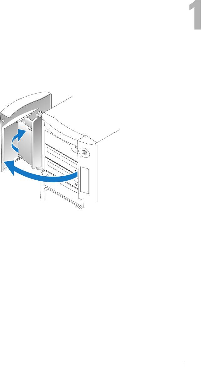
Setting Up and Using Your Computer
Opening the Drive Door
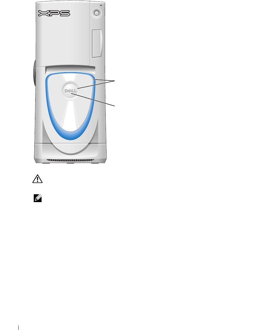
Changing the Front-Panel Light Color
You can use this exclusive Dell™ XPS feature either to change the color of the front-panel light
that illuminates the Dell name and displays around the badge on the front of your computer, or
to turn off the front-panel light entirely.
Setting Up and Using Your Computer 15
You can choose from several color choices:
•Off
•Ruby
•Emerald
•Sapphire (default)
•Amber
•Amethyst
•Topaz
front-panel
www.dell.com | support.dell.com
light
•Diamond
badge
CAUTION: Before you begin any of the procedures in this section, follow the safety instructions
located in the Product Information Guide.
NOTE: The front-panel light is not for diagnostic purposes.
1
Follow the procedures in "Before You Begin" on page 69.
2
Turn on (or restart) your computer.
3
Enter system setup by pressing <F2>. (See "Entering System Setup" on page 131 for details
about entering system setup).
4
Select the
Onboard Devices
option.
5
Select
Front LED Color
, and press <Enter>.
6
Press the left- and right- arrow keys to scroll through the color options. The front-panel light
color changes as you scroll through the options.
7
Select the color you want, and press <Enter>.
8
Press
<
Esc
>
, and press
Save and Exit
to save the new front-panel light color setting.
16 Setting Up and Using Your Computer
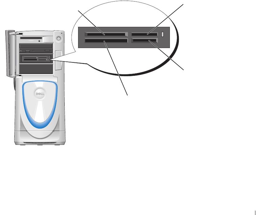
Using a Media Card Reader (Optional)
Use the media card reader to transfer data directly to your computer.
The media card reader supports the following memory types:
• xD-Picture card
• SmartMedia (SMC)
• CompactFlash Type I and II (CF I/II)
• MicroDrive card
• SecureDigital card (SD)
• MultiMediaCard (MMC)
• Memory Stick (MS/MS Pro)
For information on installing a media card reader, see "Installing a Media Card Reader" on
page 106.
xD-Picture card
Memory Stick
and SmartMedia (SMC)
(MS/MS Pro)
SecureDigital card (SD)/
MultiMediaCard (MMC)
CompactFlash Type I
and II (CF I/II) and
MicroDrive card
To use the media card reader:
1
Check the media or card to determine the proper orientation for insertion.
2
Slide the media or card into the appropriate slot until it is completely seated in the connector.
If you encounter resistance, do not force the media or card. Check the card orientation and
try again.
Setting Up and Using Your Computer 17
Connecting Monitors
CAUTION: Before you begin any of the procedures in this section, follow the safety instructions
located in the Product Information Guide.
NOTE: Dependent upon options selected when you purchased your computer, your video card may have
either two DVI ports or one DVI port and one VGA port.
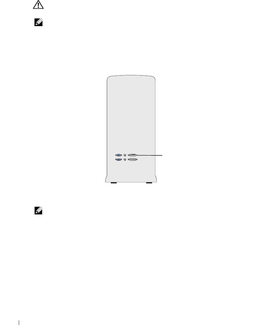
Connecting a Monitor to a PCI Express Graphics Card Dual Configuration
If you are using PCI Express graphics cards in a dual configuration, only a single monitor is
supported. Connect the monitor to the primary video card or the monitor will not function.
www.dell.com | support.dell.com
primary video card
Connecting Two Monitors
NOTE: Your graphics card and configuration must support dual monitors for you to connect and enable
two monitors using the instructions in this section.
The graphics card that came with your computer has an S-video port and either two DVI ports
and a DVI-to-VGA adapter, or one DVI port and one VGA port.
To connect a monitor by attaching the DVI or VGA connector of the monitor directly to the
DVI or the (optional) VGA port on your computer, see "Connecting Two Monitors (Without an
Adapter)" on page 19. If you purchased a graphics card that has two DVI ports instead of a VGA
port and need to use a VGA monitor, see "Connecting Two Monitors (With the Use of an
Adapter)" on page 20.
18 Setting Up and Using Your Computer
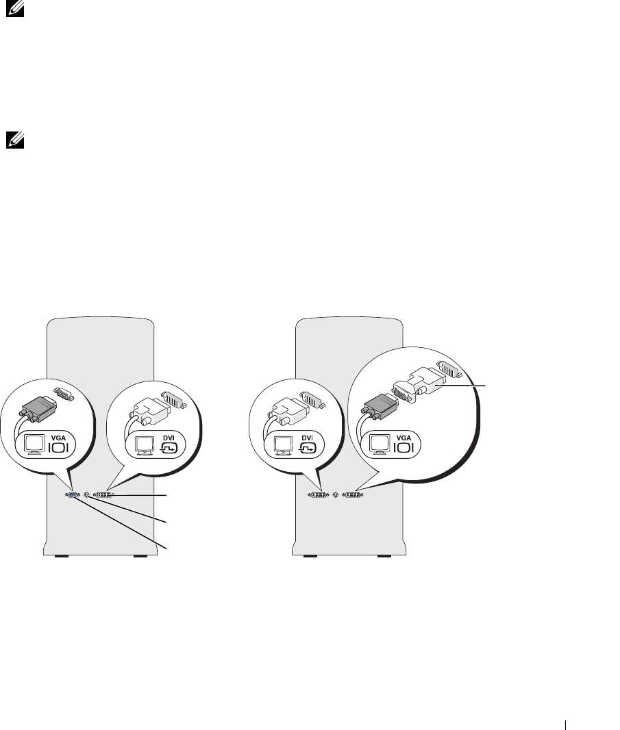
Connecting Two Monitors (Without an Adapter)
NOTE: Dependent upon options selected when you purchased your computer, your video card may have
either two DVI ports or one DVI port and one VGA port.
Follow these instructions if you are connecting two monitors with DVI connectors to the two
optional DVI ports on your computer, or if you are connecting one monitor with a DVI
connector and one VGA monitor to the DVI and optional VGA ports on your computer.
If you have a monitor with a VGA connector, but your computer has two DVI ports, follow the
instructions in "Connecting Two Monitors (With the Use of an Adapter)" on page 20.
NOTE: If you are using PCI Express graphics cards in a dual configuration, only a single monitor is
supported.
1
Follow the procedures in "Before You Begin" on page 69.
2
Connect each of the monitors to a the appropriate connector on the back of the computer.
If your monitor has a DVI connector, use the white DVI port on your computer.
If your monitor has a VGA connector, use the (optional) blue VGA port on your computer.
3
Change the display settings to support both monitors (see "Changing the Display Settings to
Support Two Monitors" on page 20).
DVI-to-VGA
adapter
DVI (white) connector
TV-OUT connector
VGA (blue) connector
(optional)
Setting Up and Using Your Computer 19

Connecting Two Monitors (With the Use of an Adapter)
Follow these instructions if you purchased a graphics card that has two DVI ports instead of a
VGA port and need to use a VGA monitor.
NOTE: If you are using PCI Express graphics cards in a dual configuration, only a single monitor is
supported.
1
Follow the procedures in "Before You Begin" on page 69.
2
Attach the DVI connector on the appropriate monitor to the white DVI port on the back of
the computer.
NOTE: Your graphics card must support a VGA monitor being connected to the DVI port.
3
Connect the DVI-to-VGA adapter to the VGA connector on the other monitor, then connect
www.dell.com | support.dell.com
the adapter to the white DVI port on the back of the computer.
4
Change the display settings to support both monitors (see "Changing the Display Settings to
Support Two Monitors" on page 20).
Connecting a TV
NOTE: If you are connecting a TV, you may connect only one monitor (VGA or DVI) in addition to the TV.
NOTE: See the documentation that came with your TV to ensure that you properly configure and connect
the TV.
To connect a TV to your computer, you must purchase an S-video cable, which is available at
most consumer electronics stores. An S-video cable is not included with your computer.
1
Follow the procedures in "Before You Begin" on page 69.
2
Connect one end of the S-video cable to the TV-OUT connector on the back of the computer.
3
Connect the other end of the S-video cable to the S-video input connector on your TV.
4
Connect one VGA or DVI monitor as described in the preceding subsection, "Connecting
Two Monitors (Without an Adapter)" on page 19.
Changing the Display Settings to Support Two Monitors
1
After you connect the monitors, turn on the computer.
®
®
The Microsoft
Windows
desktop displays on the primary monitor.
2
Enable clone mode or extended desktop mode in the display settings.
• In clone mode, both monitors display the same image.
• In extended desktop mode, you can drag objects from one screen to the other, effectively
doubling the amount of viewable work space.
For information on changing the display settings for your graphics card, see the user’s guide in
the Help and Support Center (click the
Start
button, click
Help and Support
, click
User and
system guides
, click
Device guides
, and then click the guide for your graphics card).
20 Setting Up and Using Your Computer
