Dell PowerVault MD3600i – страница 5
Инструкция к Компьютерным аксессуарам Dell PowerVault MD3600i
Оглавление
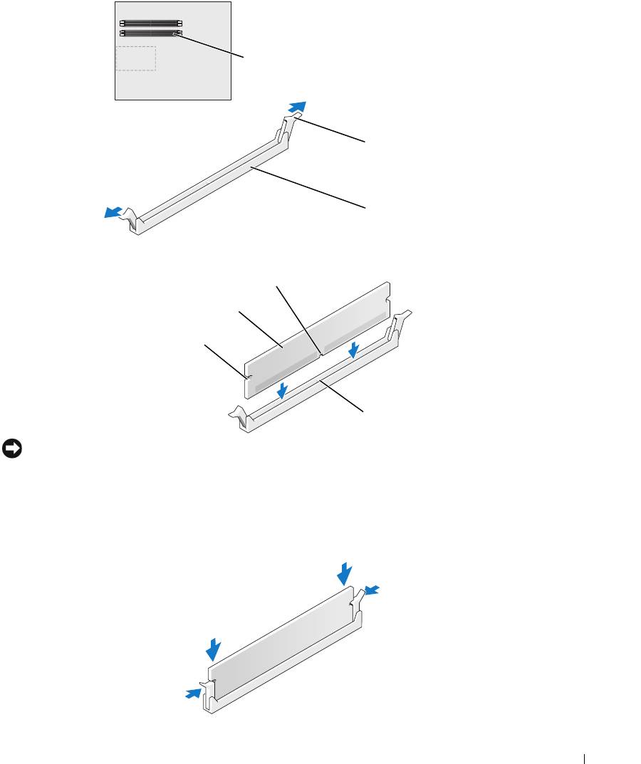
memory connector
closest to processor
securing clips (2)
connector
4
Align the notch on the bottom of the module with the crossbar in the connector.
notch
memory module
cutouts (2)
crossbar
NOTICE: To avoid damage to the memory module, press the module straight down into the connector
while you apply equal force to each end of the module.
5
Insert the module into the connector until the module snaps into position.
If you insert the module correctly, the securing clips snap into the cutouts at each end of the
module.
Removing and Installing Parts 81
6
Close the computer cover.
NOTICE: To connect a network cable, first plug the cable into the network port or device and then plug it
into the computer.
7
Connect your computer and devices to electrical outlets, and turn them on.
8
When the message appears stating that memory size has changed, press <F1> to continue.
9
Log on to your computer.
10
Right-click the
My Computer
icon on your Windows desktop and click
Properties
.
11
Click the
General
tab.
12
To verify that the memory is installed correctly, check the amount of memory (RAM) listed.
www.dell.com | support.dell.com
Removing Memory
CAUTION: Before you begin any of the procedures in this section, follow the safety instructions
located in the Product Information Guide.
NOTICE: To prevent static damage to components inside your computer, discharge static electricity
from your body before you touch any of your computer’s electronic components. You can do so by
touching an unpainted metal surface on the computer chassis.
1
Follow the procedures in "Before You Begin" on page 69.
2
Press out the securing clip at each end of the memory module connector.
3
Grasp the module and pull up.
If the module is difficult to remove, gently ease the module back and forth to remove it from
the connector.
Cards
CAUTION: Before you begin any of the procedures in this section, follow the safety instructions in the
Product Information Guide.
NOTICE: To prevent static damage to components inside your computer, discharge static electricity
from your body before you touch any of your computer’s electronic components. You can do so by
touching an unpainted metal surface on the computer.
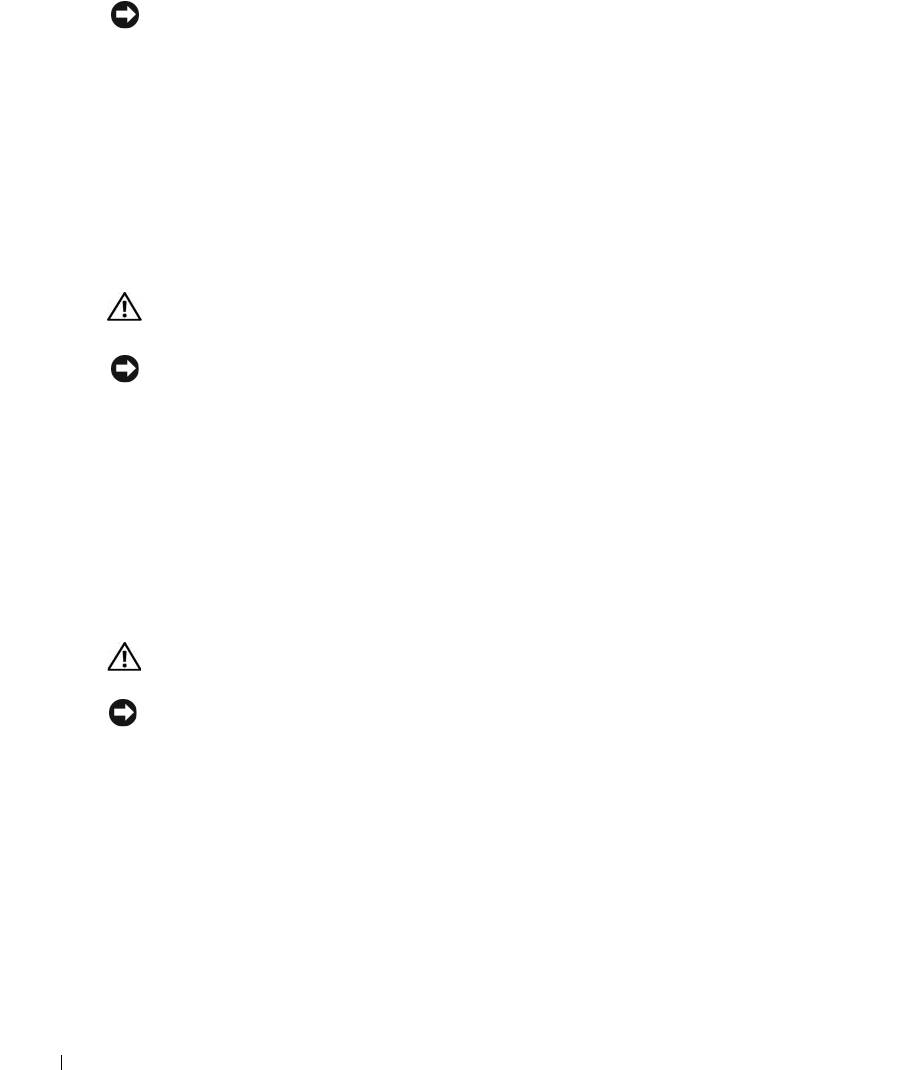
Your Dell™ computer provides the following slots for PCI and PCI Express cards:
• Three PCI card slots
• Two PCI Express x16 card slots (can be used in a dual-graphics configuration)
82 Removing and Installing Parts
NOTE: If a graphics card is installed in each of the PCI Express x16 card slots in the dual-graphics
configuration, the PCI Express x1 card slot is not accessible for use.
• One PCI Express x1 card slot
PCI card
PCI Express x16
PCI Express x1
card
card
PCI Express x16
PCI Express x1
card slot
card slot
Removing and Installing Parts 83
Removing a PCI Express Graphics Card from a Dual Configuration
NOTE: This section regards dual configurations of PCI Express graphics cards only. For removal of any
other type of PCI or PCI Express cards, see "Removing PCI and PCI Express Cards" on page 89.
1
Follow the procedures in ""Before You Begin" on page 69.
2
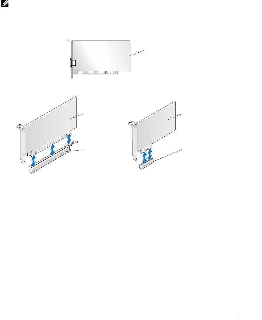
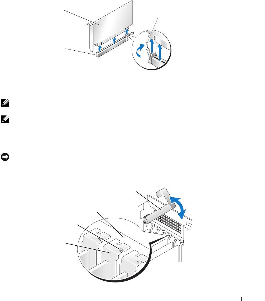
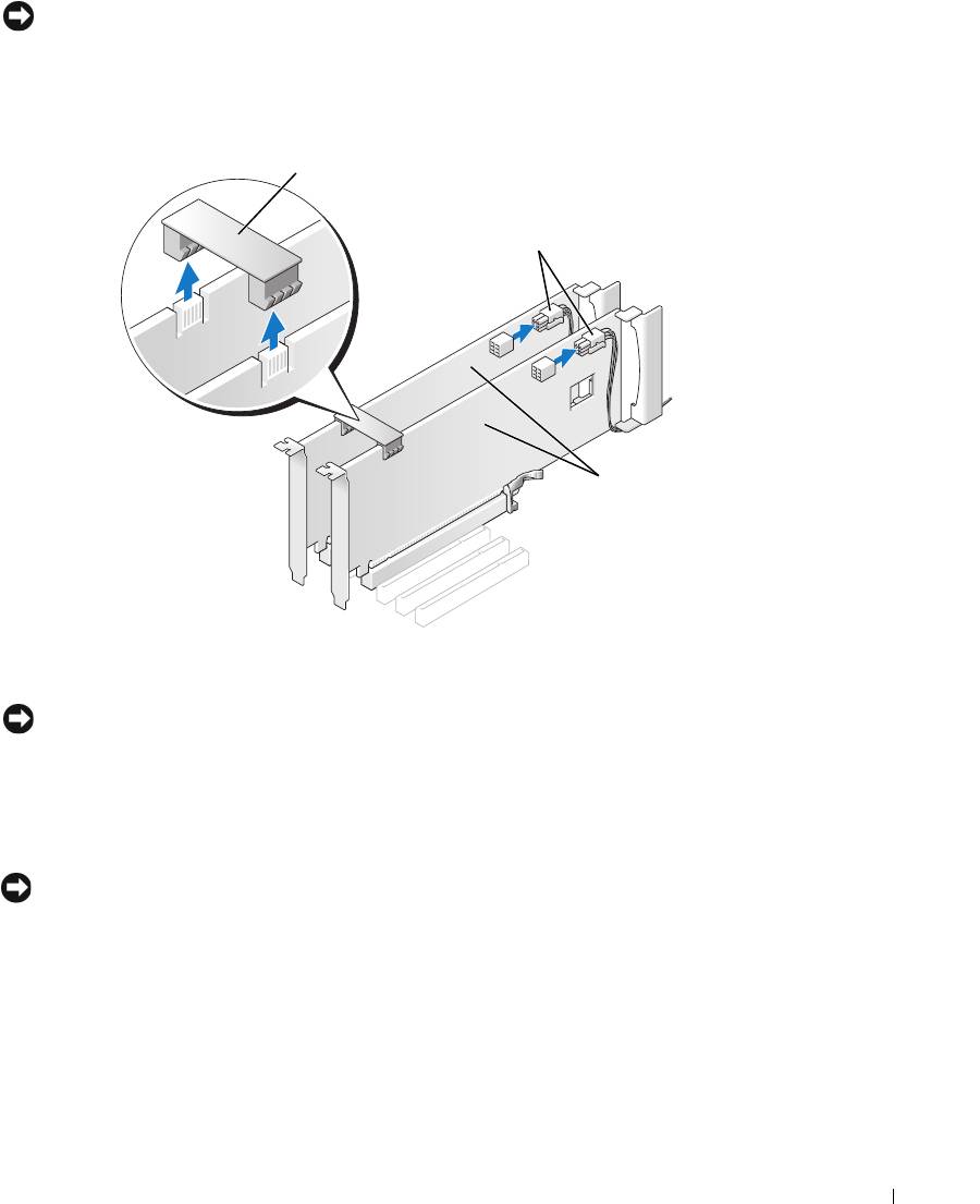
Gently securing both graphics cards with one hand, remove the graphics card bridge with your
other hand by pulling it up and away from the computer. Set it aside.
graphics card bridge
power connectors (2)
www.dell.com | support.dell.com
dual-PCI Express
graphics cards
3
Disconnect the power cable connected to the card.
4
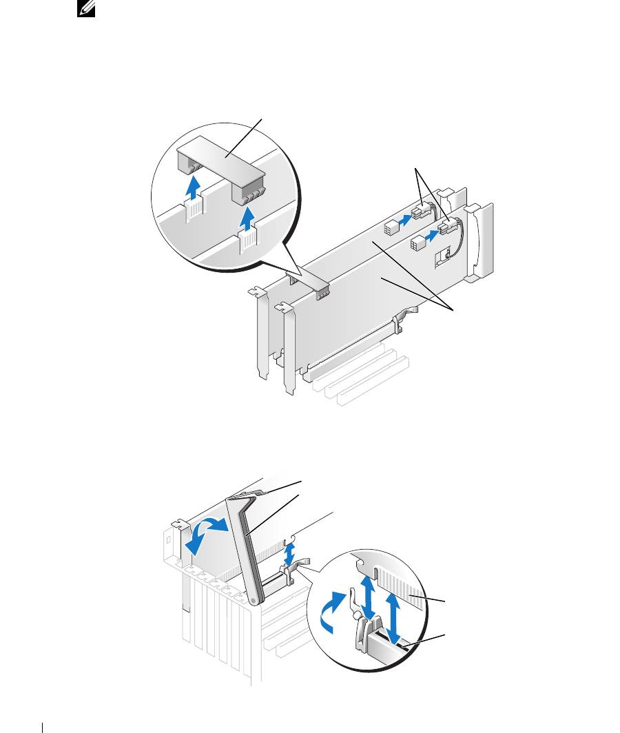
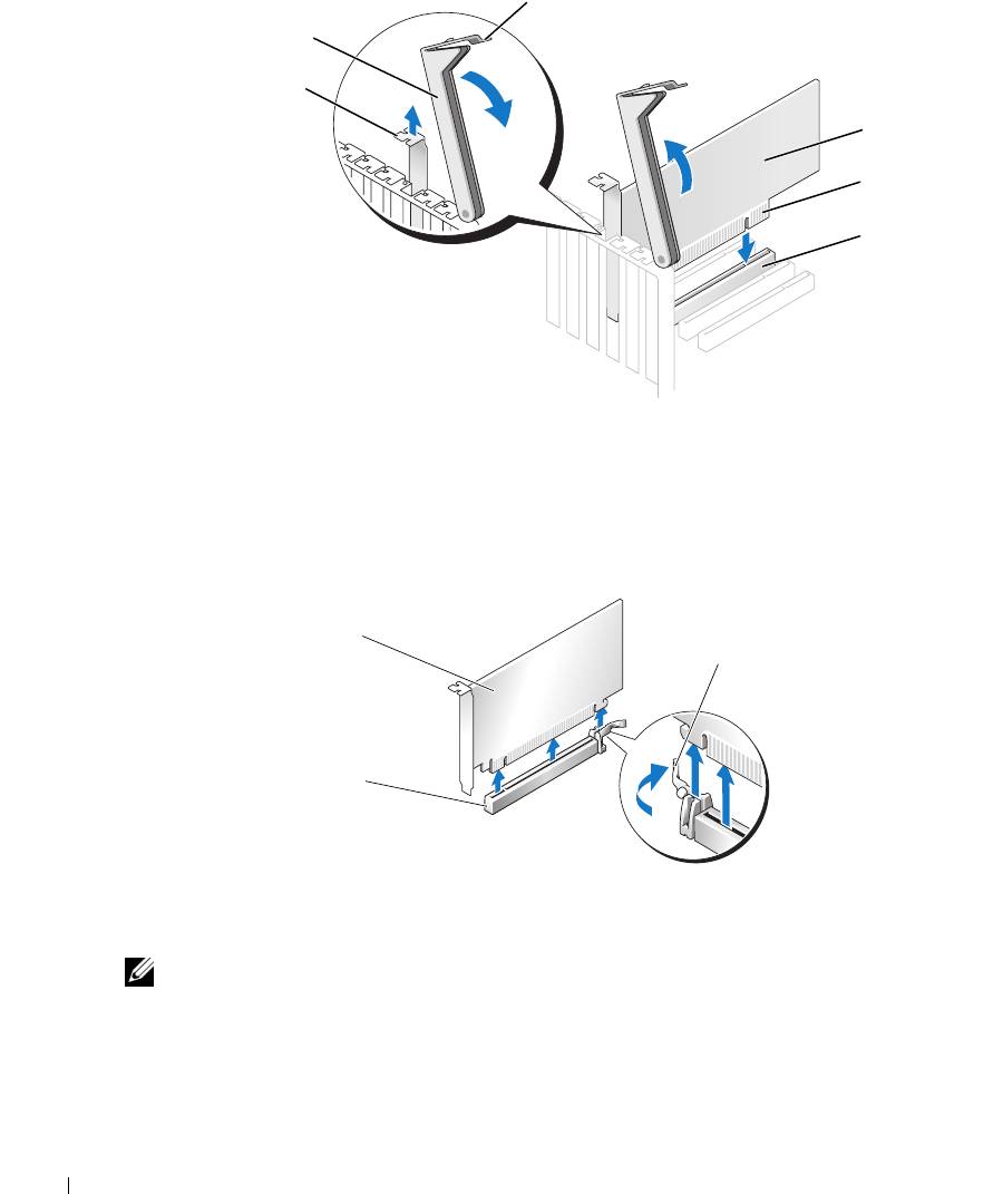
Press the lever on the card retention arm and raise the retention arm.
lever
retention arm
edge connector
card connector
84 Removing and Installing Parts
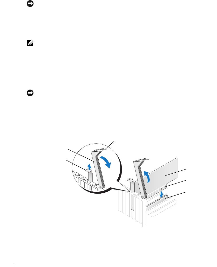
5
Pull the securing tab (if present), grasp the card by its top corners, and ease it out of its
connector.
PCI Express
x16 card
securing tab
PCI Express x16
card slot
6
If you are replacing the card, see "Installing PCI Express Graphics Cards in a Dual
Configuration" on page 86.
If you are not replacing the card, install a filler bracket in the empty card-slot opening.
NOTE: Installing filler brackets over empty card-slot openings is necessary to maintain FCC certification
of the computer. The brackets also keep dust and dirt out of your computer.
NOTE: The graphics card bridge is unnecessary in a single card configuration.
7
Before you lower the retention arm, ensure that:
• The tops of all cards and filler brackets are flush with the alignment bar.
• The notch in the top of the card or filler bracket fits around the alignment guide.
NOTICE: Do not route card cables over or behind the cards. Cables routed over the cards can prevent
the computer cover from closing properly or cause damage to the equipment.
8
Press the retention arm into place, securing the card(s) in the computer.
retention arm
alignment bar
alignment guide
filler bracket
Removing and Installing Parts 85
NOTICE: To connect a network cable, first plug the cable into the network port or device and then plug
the cable into the computer.
9
Replace the computer cover, reconnect the computer and devices to electrical outlets, and
then turn them on.
Installing PCI Express Graphics Cards in a Dual Configuration
NOTE: This section regards dual configurations of PCI Express graphics cards only. For installation of
any other type of PCI or PCI Express cards, see "Installing PCI and PCI Express Cards" on page 91.
The PCI Express x1 card slot is not available for use if a graphics card is installed in each of the
PCI Express x16 card slots in the dual-graphics configuration. If you are upgrading from a a
single graphics to a dual-graphics configuration, you will need to remove any card installed in
www.dell.com | support.dell.com
the PCI Express x1 card slot. See "System Board Components" on page 78 to locate the PCI
Express x1 card slot. To remove a PCI Express card, see "Removing PCI and PCI Express Cards"
on page 89.
NOTICE: For information about upgrading your system to use NVIDIA SLI (Scalable Link Interface) dual-
graphics technology, see the Dell website at support.dell.com.
To learn more about NVIDIA SLI (Scalable Link Interface) dual-graphics technology, see
"NVIDIA SLI Dual Graphics Technology" on page 38.
1
Follow the procedures in "Before You Begin" on page 69.
2
Press the lever on the card retention arm and raise the retention arm.
lever
retention arm
filler bracket
PCI card
edge connector
card connector
3
If you are upgrading to a dual-graphics configuration, remove the filler bracket to create a
card-slot opening.
86 Removing and Installing Parts
4
If you are upgrading to a dual-graphics configuration and have a card installed in the PCI
Express x1 card slot, remove the card. See "Removing PCI and PCI Express Cards" on
page 89.
5
Prepare the card for installation.
See the documentation that came with the card for information on configuring the card,
making internal connections, or otherwise customizing it for your computer.
6
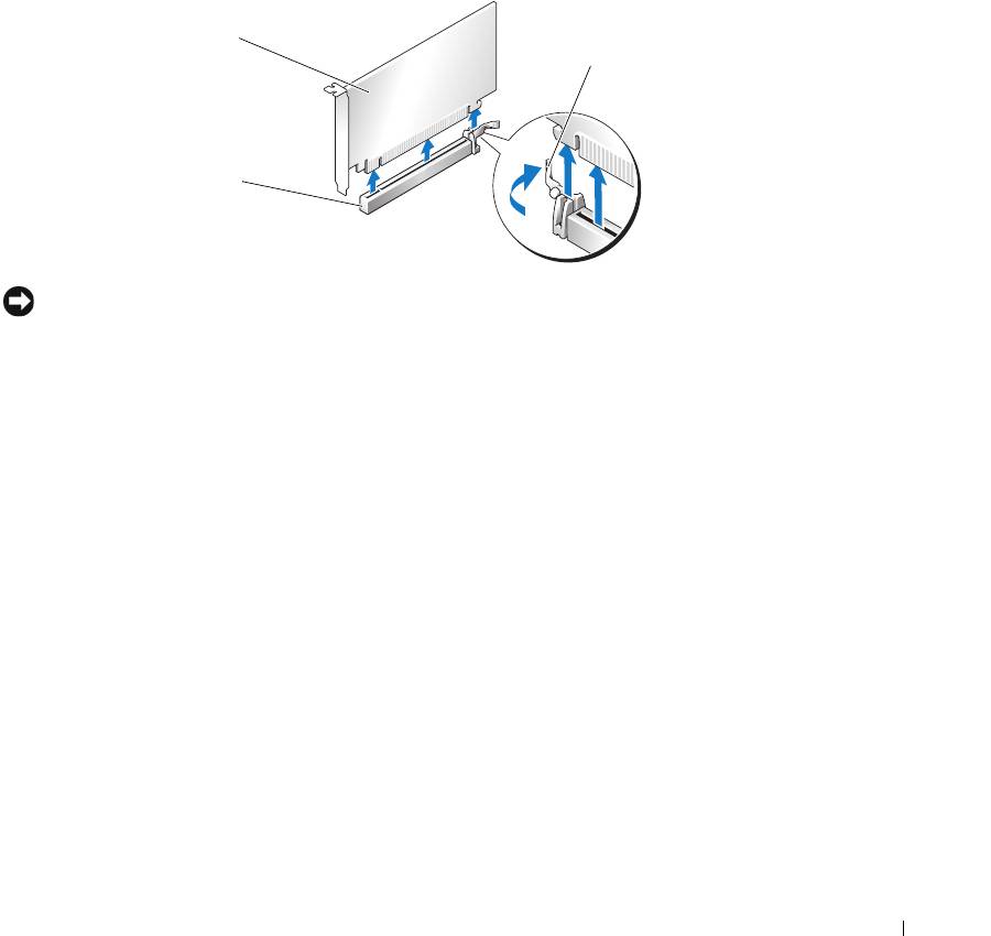
Position the card so that it is aligned with the slot and the securing tab (if present) is aligned
with the securing slot.
PCI Express
x16 card
securing tab
PCI Express x16
card slot
NOTICE: Ensure that you release the securing tab to seat the card. If the card is not installed correctly,
you may damage the system board.
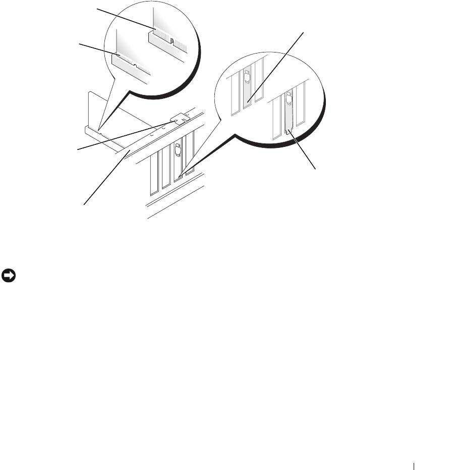
7
Gently pull the securing tab (if present) and place the card in the connector. Press down
firmly and ensure that the card is fully seated in the slot.
Removing and Installing Parts 87
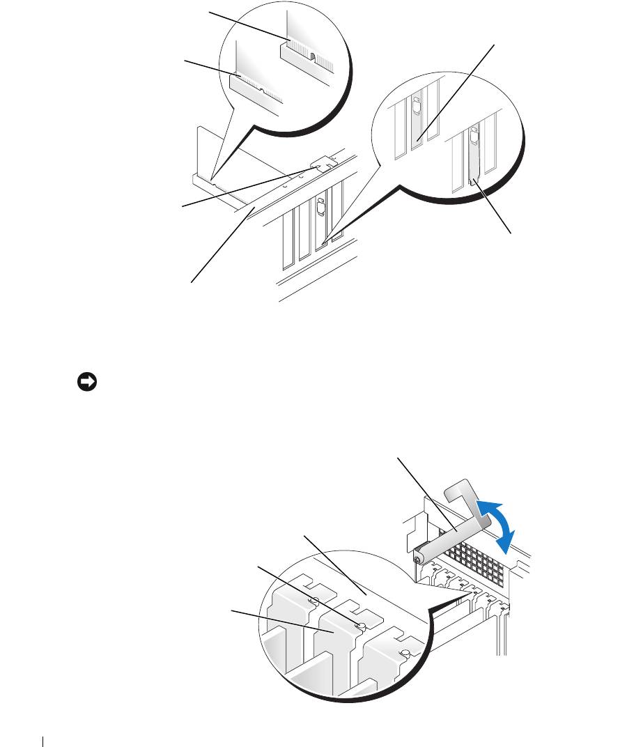
not fully seated card
bracket within
fully seated card
slot
www.dell.com | support.dell.com
bracket caught
outside of slot
8
Before you lower the retention arm, ensure that:
• The tops of all cards and filler brackets are flush with the alignment bar.
• The notch in the top of the card or filler bracket fits around the alignment guide.
NOTICE: Do not route card cables over or behind the cards. Cables routed over the cards can prevent
the computer cover from closing properly or cause damage to the equipment.
9
Press the retention arm into place, securing the card(s) in the computer.
88 Removing and Installing Parts
a
lignment guide
alignment bar
retention arm
alignment bar
alignment guide
filler bracket
NOTICE: An incorrectly attached graphics power cable may result in degraded graphics performance.
10
Connect the power cable to the power connector on the card.
For information about the card cable connections, see the documentation that came with the
card.
graphics card bridge
power connectors (2)
dual-PCI Express
graphics cards
11
Replace the graphics card bridge, pressing firmly so that it completely covers the connector
tabs.
NOTICE: To connect a network cable, first plug the cable into the network port or device and then plug
the cable into the computer.
12
Replace the computer cover, reconnect the computer and devices to electrical outlets, and
then turn them on.
Removing PCI and PCI Express Cards
NOTICE: If you have the optional dual-graphics configuration, see "Removing a PCI Express Graphics
Card from a Dual Configuration" on page 84 to remove or replace a graphics card.
1
Follow the procedures in "Before You Begin" on page 69.
2
Press the lever on the card retention arm and raise the retention arm.
Removing and Installing Parts 89
lever
retention arm
filler bracket
PCI card
edge connector
card connector
www.dell.com | support.dell.com
3
Remove the card:
a
If necessary, disconnect any cables connected to the card.
b
Pull the securing tab (if present), grasp the card by its top corners, and ease it out of its
connector.
PCI Express
x16 card
securing tab
PCI Express x16
card slot
4
If you are replacing the card, see "Installing PCI and PCI Express Cards" on page 91.
If you are not replacing the card, install a filler bracket in the empty card-slot opening.
NOTE: Installing filler brackets over empty card-slot openings is necessary to maintain FCC certification
of the computer. The brackets also keep dust and dirt out of your computer.
5
Before you lower the retention arm, ensure that:
• The tops of all cards and filler brackets are flush with the alignment bar.
• The notch in the top of the card or filler bracket fits around the alignment guide.
90 Removing and Installing Parts
NOTICE: Do not route card cables over or behind the cards. Cables routed over the cards can prevent
the computer cover from closing properly or cause damage to the equipment.
6
Press the retention arm into place, securing the card(s) in the computer.
retention arm
alignment bar
alignment guide
filler bracket
NOTICE: To connect a network cable, first plug the cable into the network port or device and then plug
the cable into the computer.
7
Replace the computer cover, reconnect the computer and devices to electrical outlets, and
then turn them on.
8
If you removed a sound card or a network adapter, see "Network Adapter and Sound Card
Settings" on page 94.
9
Uninstall the driver for the card that you removed.
Installing PCI and PCI Express Cards
NOTICE: If you have or are upgrading to the optional dual-graphics configuration, see "Installing PCI
Express Graphics Cards in a Dual Configuration" on page 86 to install a graphics card.
1
Follow the procedures in "Before You Begin" on page 69.
2
Press the lever on the card retention arm and raise the retention arm.
Removing and Installing Parts 91
lever
retention arm
filler bracket
PCI card
edge connector
card connector
www.dell.com | support.dell.com
3
If you are installing a new card, remove the filler bracket to create a card-slot opening.
4
Prepare the card for installation.
See the documentation that came with the card for information on configuring the card,
making internal connections, or otherwise customizing it for your computer.
CAUTION: Some network adapters automatically start the computer when they are connected to a
network. To guard against electrical shock, be sure to unplug your computer from its electrical outlet
before installing any cards.
5
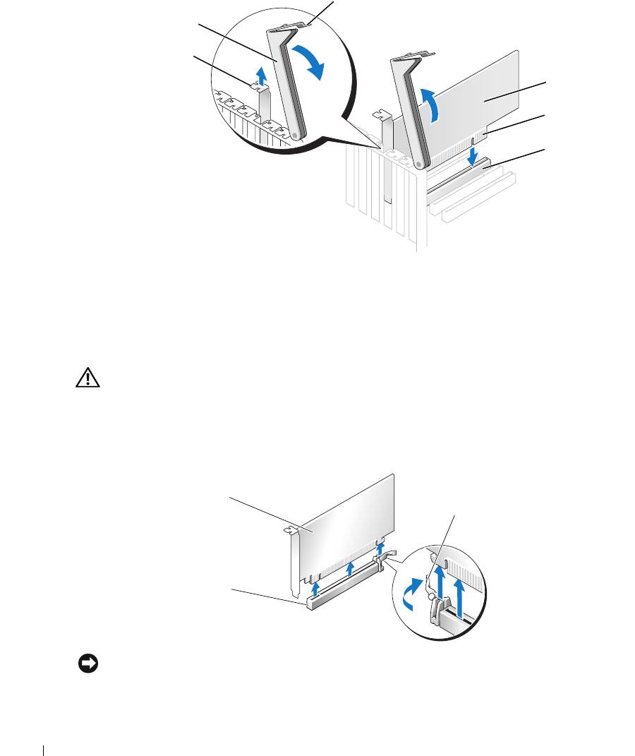
Position the card so that it is aligned with the slot and (if present) the securing tab is aligned
with the securing slot.
PCI Express
x16 card
securing tab
PCI Express x16
card slot
NOTICE: Ensure that you release the securing tab to seat the card. If the card is not installed correctly,
you may damage the system board.
92 Removing and Installing Parts
6
Gently pull the securing tab (if present) and place the card in the connector. Press down
firmly and ensure that the card is fully seated in the slot.
If the card is full-length, insert the end of the card into the card guide bracket as you lower the
card toward its connector on the system board. Insert the card firmly into the card connector
on the system board.
not fully seated card
bracket within
fully seated card
slot
bracket caught
outside of slot
7
Before you lower the retention arm, ensure that:
• The tops of all cards and filler brackets are flush with the alignment bar.
• The notch in the top of the card or filler bracket fits around the alignment guide.
NOTICE: Do not route card cables over or behind the cards. Cables routed over the cards can prevent
the computer cover from closing properly or cause damage to the equipment.
8
Press the retention arm into place, securing the card(s) in the computer.
Removing and Installing Parts 93
a
lignment guide
alignment bar
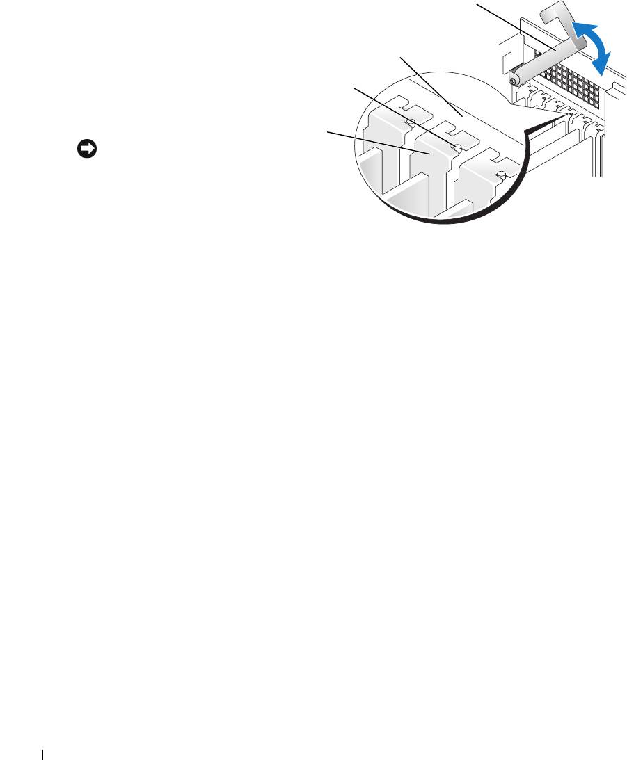
retention arm
9
Connect any cables that
should be attached to
the card.
alignment bar
See the documentation
alignment guide
for the card for
information about the
card cable connections.
filler bracket
NOTICE: To connect a
network cable, first plug the
cable into the network port
or device and then plug the
www.dell.com | support.dell.com
cable into the computer.
10
Replace the computer
cover, reconnect the computer and devices to electrical outlets, and then turn them on.
11
If you installed a sound card or a network adapter, see "Network Adapter and Sound Card
Settings" on page 94.
12
Install any drivers required for the card as described in the card documentation.
Network Adapter and Sound Card Settings
If you installed a sound card:
1
Enter system setup, select
Integrated Audio Controller
, and then change the setting to
Off
.
2
Connect external audio devices to the sound card connectors. Do not connect external audio
devices to the microphone, speaker/headphone, or line-in connectors on the back panel.
If you removed a sound card:
1
Enter system setup, select
Integrated Audio Controller
, and then change the setting to
On
.
2
Connect external audio devices to the audio connectors on the back panel of the computer.
If you installed an add-in network adapter and want to disable the integrated network adapter:
1
Enter system setup, select
Integrated NIC Controller,
and then change the setting to
Off
.
2
Connect the network cable to the add-in network adapter connectors. Do not connect the
network cable to the integrated connector on the back panel.
If you removed an add-in network connector:
1
Enter system setup, select
Integrated NIC Controller
, and then change the setting to
On
.
2
Connect the network cable to the integrated connector on the back panel of the computer.
94 Removing and Installing Parts
Drives
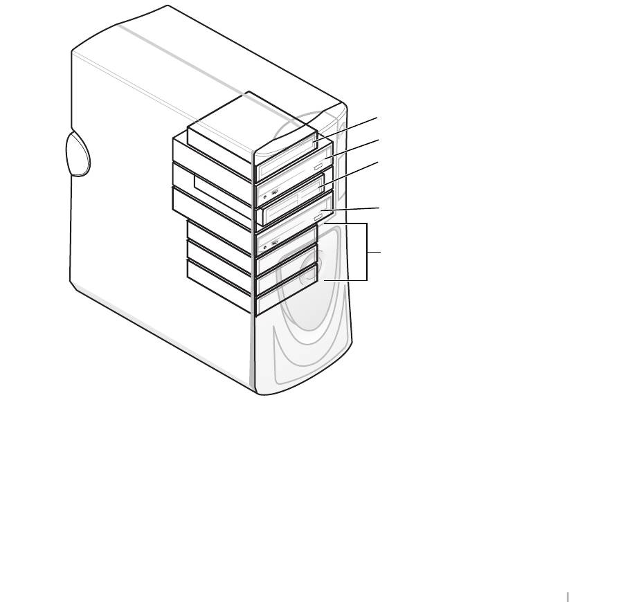
Your computer supports a combination of these devices:
• Up to three hard drives
• Optional floppy drive
• Up to two CD or DVD drives
• Optional media card reader
floppy drive
CD/DVD drive
media card reader
(optional)
CD/DVD drive
(optional)
hard drive(s)
General Installation Guidelines
Connect serial ATA hard drives to the SATA0 - SATA3 connectors on the system board. Connect
CD/DVD drives to the IDE connector.
When you connect two IDE devices to a single IDE interface cable and configure them for the
cable select setting, the device attached to the last connector on the interface cable is the
primary or the boot device (drive 0), and the device attached to the middle connector on the
interface cable is the secondary device (drive 1). See the drive documentation in your upgrade
kit for information on configuring devices for the cable select setting.
Removing and Installing Parts 95
Connecting Drive Cables
When you install a drive, you connect two cables—a DC power cable and a data cable—to the
back of the drive and to the system board. Some drives may also have an audio connector; one
end of the audio cable attaches to the drive connector and the other end attaches to the system
board.
Drive Interface Connectors
Most interface connectors are keyed for correct insertion; that is,
a notch or a missing pin on one connector matches a tab or a
filled-in hole on the other connector.
www.dell.com | support.dell.com
When you connect an IDE cable, ensure that you align the
colored stripe with the pin 1 connector. When you disconnect an
IDE cable, grasp the colored pull tab and pull until the
connector detaches.
When connecting and disconnecting a serial ATA cable, hold the
cable by the connector at each end.
NOTE: The system board serial ATA connector may have an
attached cover or shroud.
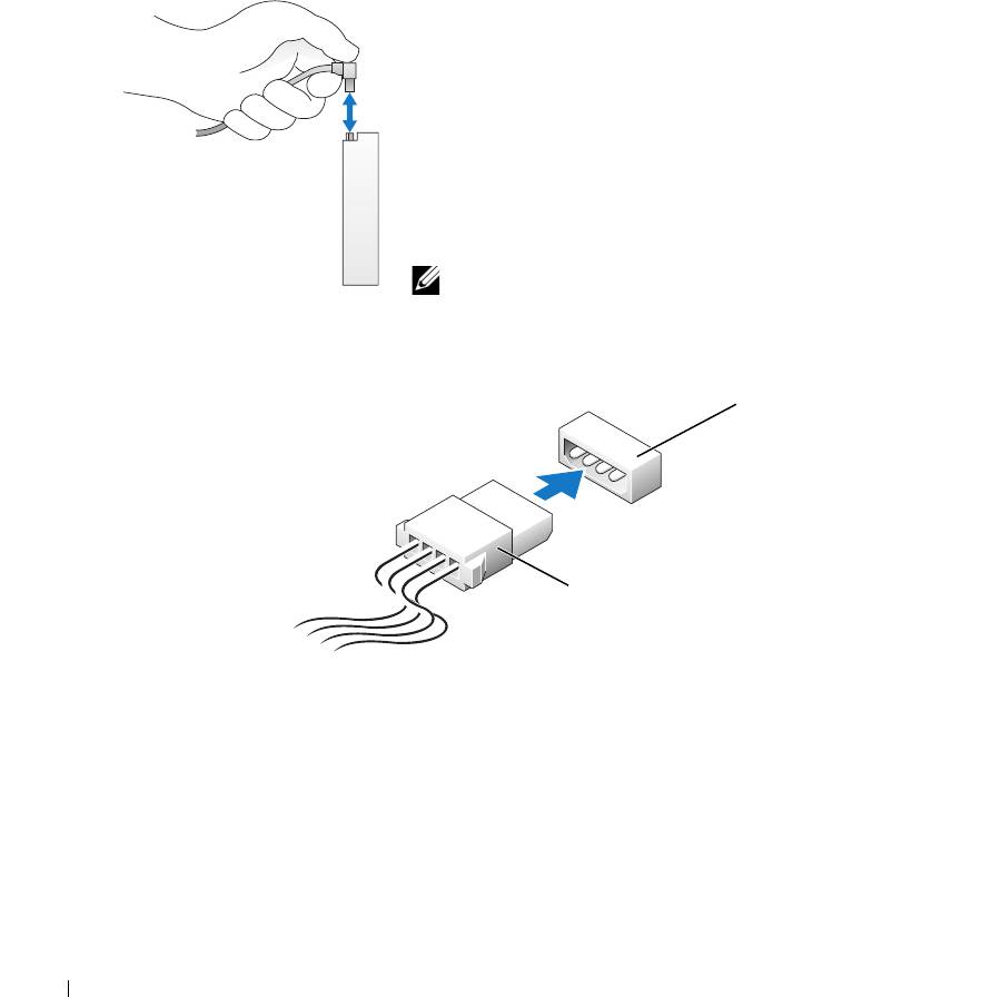
Power Cable Connector
power input
connector
power cable
96 Removing and Installing Parts
Hard Drive
CAUTION: Before you begin any of the procedures in this section, follow the safety instructions
located in the Product Information Guide.
NOTICE: To avoid damage to the drive, do not set it on a hard surface. Instead, set the drive on a
surface, such as a foam pad, that will sufficiently cushion it.
1
If you are replacing a hard drive that contains data you want to keep, back up your files before
you remove the hard drive.
2
Follow the procedures in "Before You Begin" on page 69.
Removing a Hard Drive
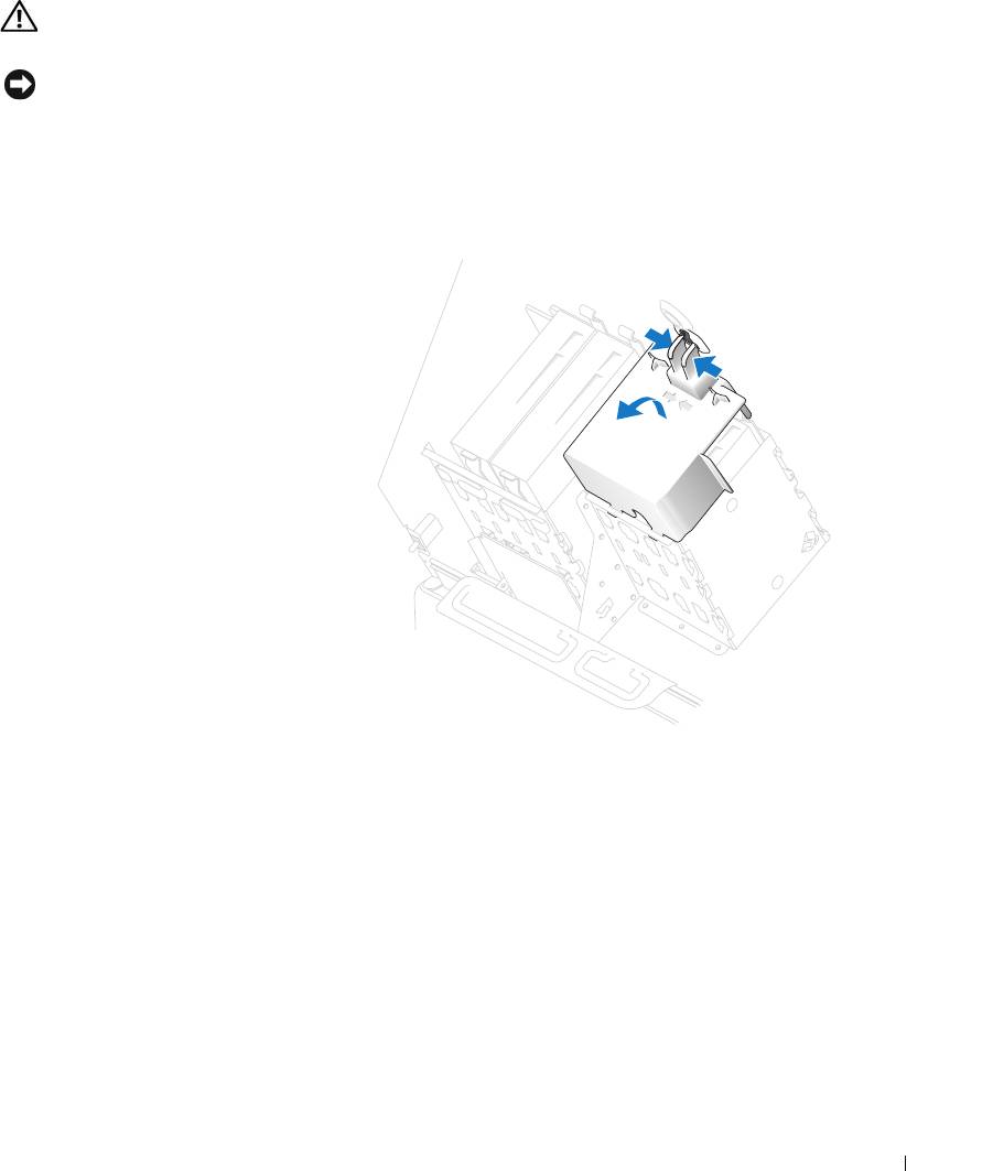
1
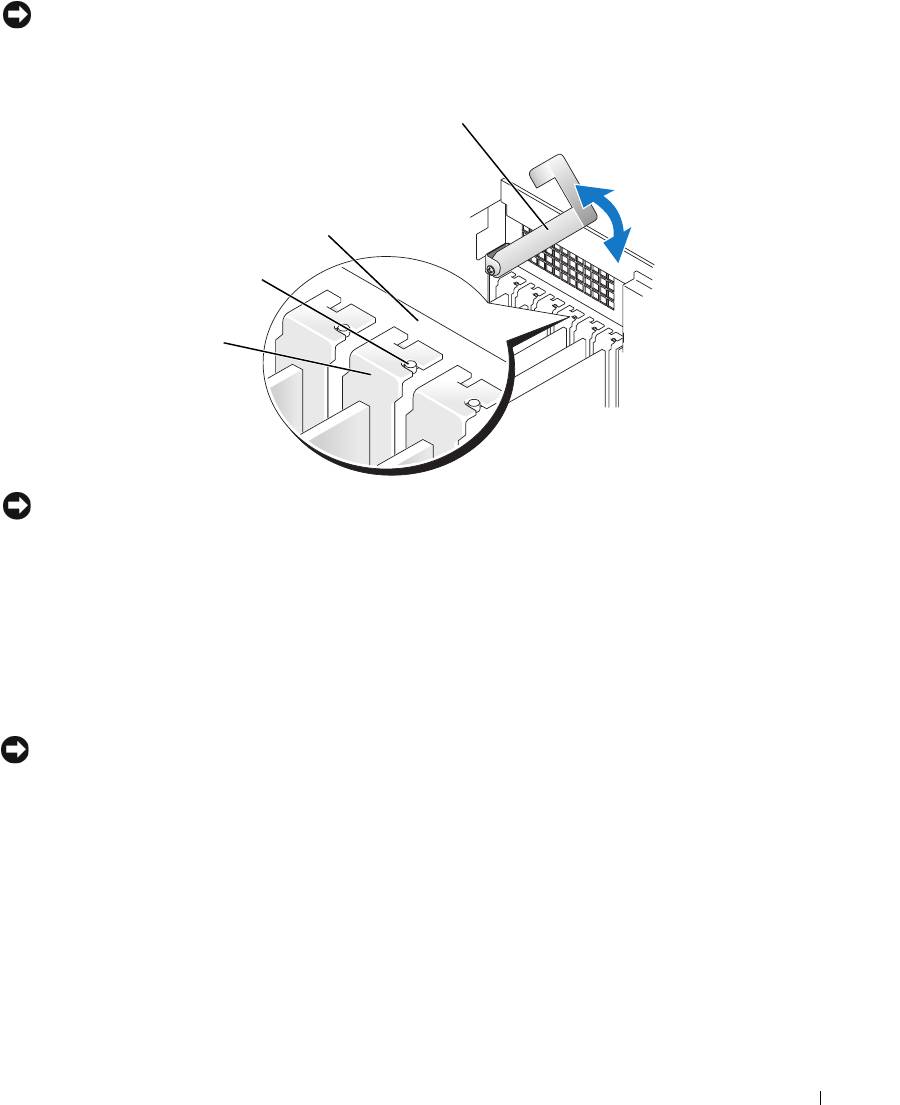
Press the top shroud tabs
towards each other and tilt the
shroud back.
2
Lift the shroud away from the
hard drive.
Removing and Installing Parts 97
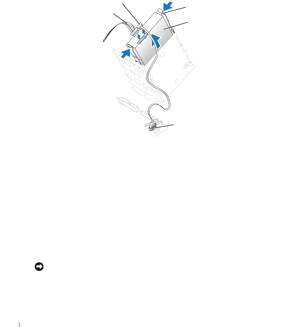
3
Disconnect the power and hard-drive cables from the drive and from the system board.
hard-drive cable
tabs (2)
power cable
hard drive
www.dell.com | support.dell.com
system board connector
4
Press the tabs on each side of the drive towards each other and slide the drive up and out.
Installing a Hard Drive
1
Unpack the new hard drive, and prepare it for installation.
2
Check the documentation for the drive to verify that it is configured for your computer.
3
If you are adding a second hard drive, remove the bracket rails from the inside of the hard-
drive bay by gently pulling the rails up and out of the bay.
4
If you are replacing a hard drive and the new drive does not have the bracket rails attached,
remove the rails from the old drive by removing the two screws that secure each rail to the
drive.
5
Attach the bracket rails to the new drive by aligning the screw holes on the drive with the
screw holes on the bracket rails and then inserting and tightening all four screws (two screws
on each rail).
6
Ensure that the rail tabs are positioned at the back of the hard drive.
NOTICE: Do not install any drive into the lower hard-drive bay until you have removed the green drive
rails from the inside of the hard-drive bay.
98 Removing and Installing Parts
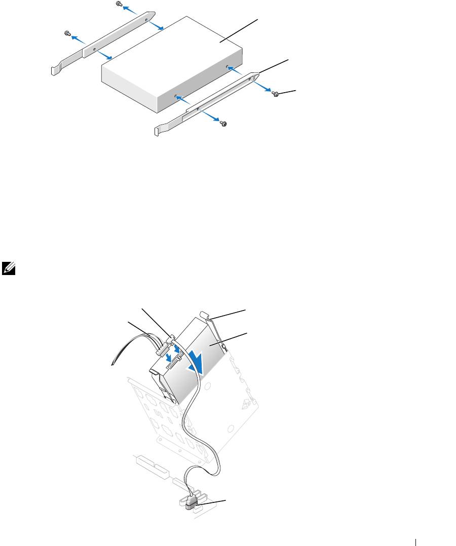
drive
bracket rails (2)
screws (4)
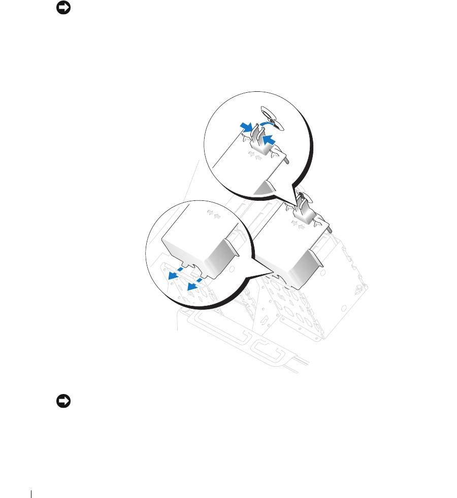
7
If you are adding a second hard drive, remove the first hard drive from the upper bay and
install it in the lower bay:
a
Disconnect the power and the hard-drive cables from the back of the first hard drive.
b
Press in the two rail tabs and pull the first hard drive out of the upper bay.
c
Gently slide the first hard drive into the lower bay until it clicks into place.
d
Reconnect the power and hard-drive cables to the back of the first hard drive.
8
Install the hard drive into the computer by gently sliding the drive into place until the tabs
securely click into position.
NOTE: If you are installing a hard drive in the lower bay, place the drive in the bay so that the power
connector is on the left-hand side (opposite of the top hard drive)
hard-drive cable
tabs (2)
power cable
hard drive
system board connector
Removing and Installing Parts 99
9
Connect a power cable to the drive.
10
Connect the hard-drive cable to the drive and to the system board (see "System Board
Components" on page 78).
11
Check all connectors to be certain that they are properly cabled and firmly seated.
NOTICE: When replacing the hard-drive shroud, ensure that all the cables are properly routed.
12
Insert the bottom tabs of the shroud into the slot on the drive cage and rotate the shroud up.
13
Press the top shroud tabs towards each other and insert them into the corresponding slot on
the chassis.
14
Gently press on the shroud to ensure that it is secure.
www.dell.com | support.dell.com
15
Close the computer cover (see "Closing the Computer Cover" on page 125).
NOTICE: To connect a network cable, first plug the cable into the network port or device and then plug it
into the computer.
16
Connect your computer and devices to electrical outlets, and turn them on.
See the documentation that came with the drive for instructions on installing any software
required for drive operation.
100 Removing and Installing Parts
