Dell PowerVault MD3600i – страница 6
Инструкция к Компьютерным аксессуарам Dell PowerVault MD3600i
Оглавление

17
If the drive that you installed is the primary drive, insert a bootable floppy disk into drive A.
18
Turn on the computer.
19
Enter system setup (see "Entering System Setup" on page 131), and update the appropriate
Drive
option.
20
Exit system setup, and restart the computer.
21
Partition and logically format your drive before you proceed to the next step.
See the documentation for your operating system for instructions.
22
Test the hard drive by running the Dell Diagnostics (see "Dell Diagnostics" on page 58).
23
If the drive you just installed is the primary drive, install your operating system on the hard
drive.
Floppy Drive
CAUTION: Before you begin any of the procedures in this section, follow the safety instructions
located in the Product Information Guide.
CAUTION: To guard against electrical shock, always unplug your computer from the electrical outlet
before opening the cover.
Removing a Floppy Drive
1
Follow the procedures in "Before You Begin" on page 69.
2
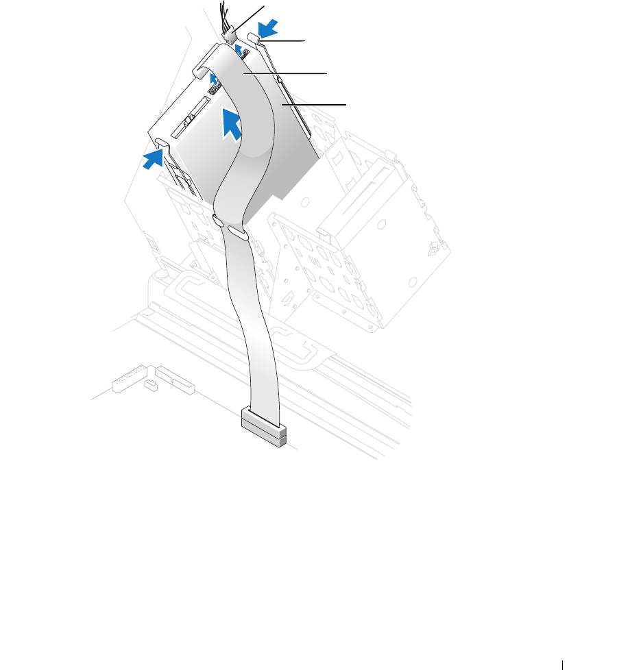
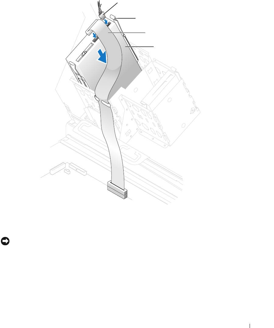
Disconnect the power and data cables from the back of the floppy drive.
3
Disconnect the other end of the data cable from the system board.
Removing and Installing Parts 101
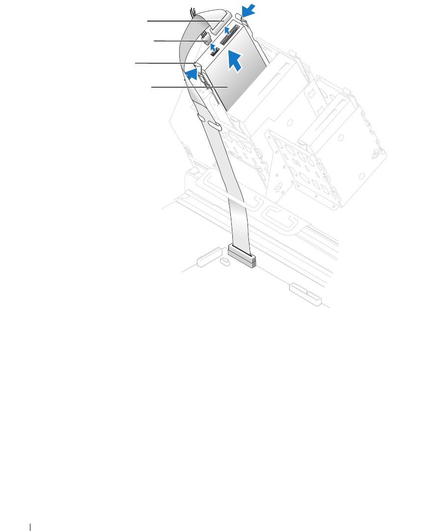
data cable
power cable
tabs (2)
floppy drive
www.dell.com | support.dell.com
4
Press inward on the two tabs on the sides of the drive, slide the drive upward, and remove it
from the floppy-drive bay.
102 Removing and Installing Parts
Installing a Floppy Drive
1
Follow the procedures in "Before You Begin" on page 69.
2
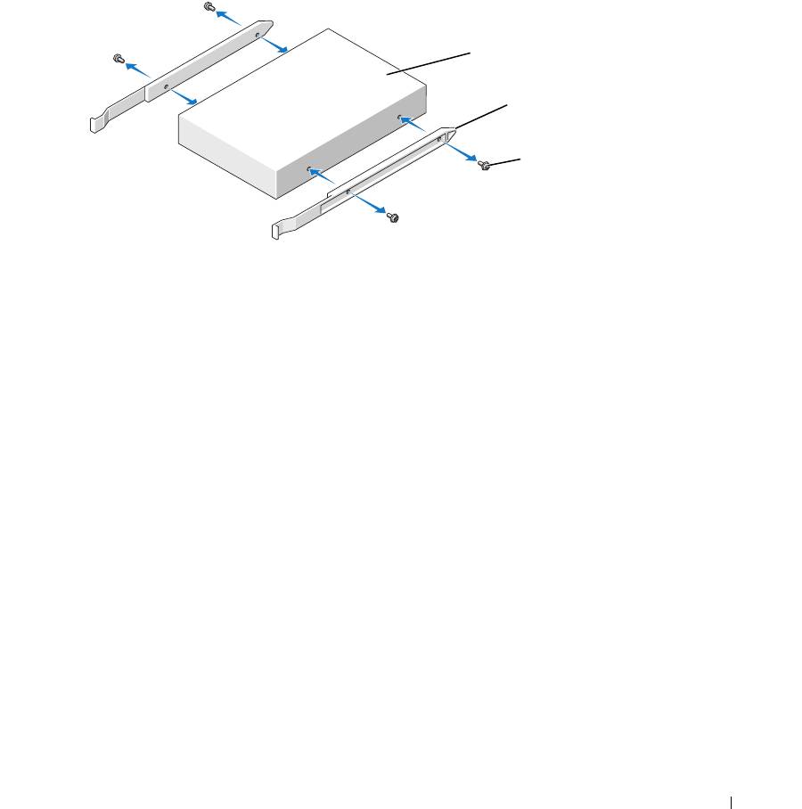
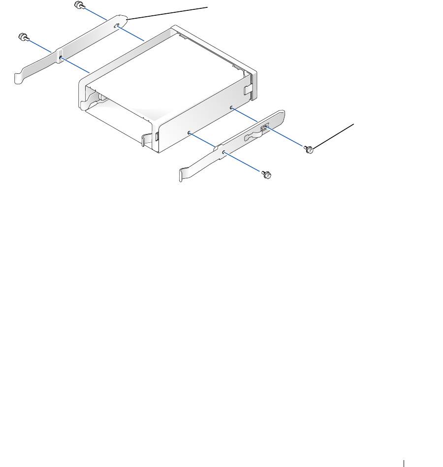
If you are replacing a drive and the new drive does not have the bracket rails attached, remove
the rails from the old drive by removing the two screws that secure each rail to the drive. Attach
the bracket to the new drive by aligning the screw holes on the drive with the screw holes on the
bracket rails and then inserting and tightening all four screws (two screws on each rail).
drive
bracket rails (2)
screws (4)
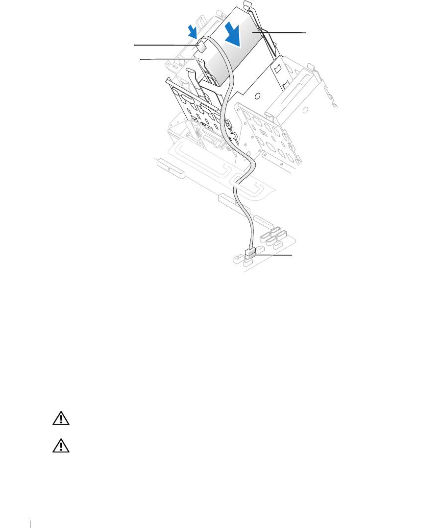
3
Gently slide the drive into place until the tabs securely click into position.
Removing and Installing Parts 103
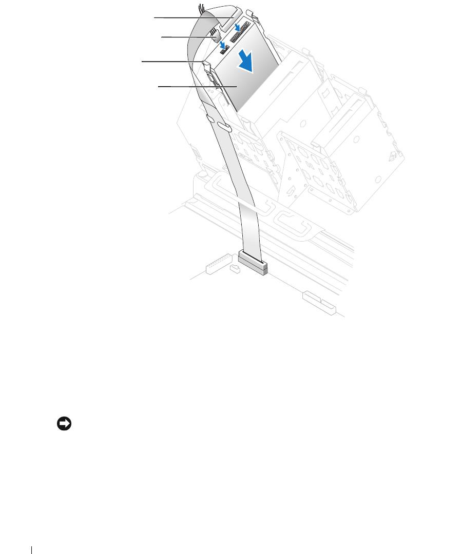
data cable
power cable
tabs (2)
floppy drive
www.dell.com | support.dell.com
4
Attach the power and data cables to the floppy drive.
5
Connect the other end of the data cable to the DSKT connector on the system board (see
"System Board Components" on page 78).
6
Check all cable connections, and fold cables out of the way to provide airflow for the fan and
cooling vents.
7
Close the computer cover (see "Closing the Computer Cover" on page 125).
NOTICE: To connect a network cable, first plug the cable into the network port or device and then plug it
into the computer.
8
Connect your computer and devices to electrical outlets, and turn them on.
See the documentation that came with the drive for instructions on installing any software
required for drive operation.
9
Enter system setup (see "System Setup" on page 131) and update the appropriate
Diskette
Drive
option.
104 Removing and Installing Parts

10
Verify that your computer works correctly by running the Dell Diagnostics (see "Dell
Diagnostics" on page 58).
Media Card Reader
For information on using the media card reader, see "Using a Media Card Reader (Optional)" on
page 17.
Removing a Media Card Reader
CAUTION: Before you begin any of the procedures in this section, follow the safety instructions
located in the Product Information Guide.
NOTICE: To prevent static damage to components inside your computer, discharge static electricity
from your body before you touch any of your computer’s electronic components. You can do so by
touching an unpainted metal surface on the computer chassis.
1
Follow the procedures in "Before You Begin" on page 69.
2
Lay the computer on its side so that the system board is on the bottom of the inside of the
computer.
3
Open the computer cover ("Opening the Computer Cover" on page 76).
Removing and Installing Parts 105
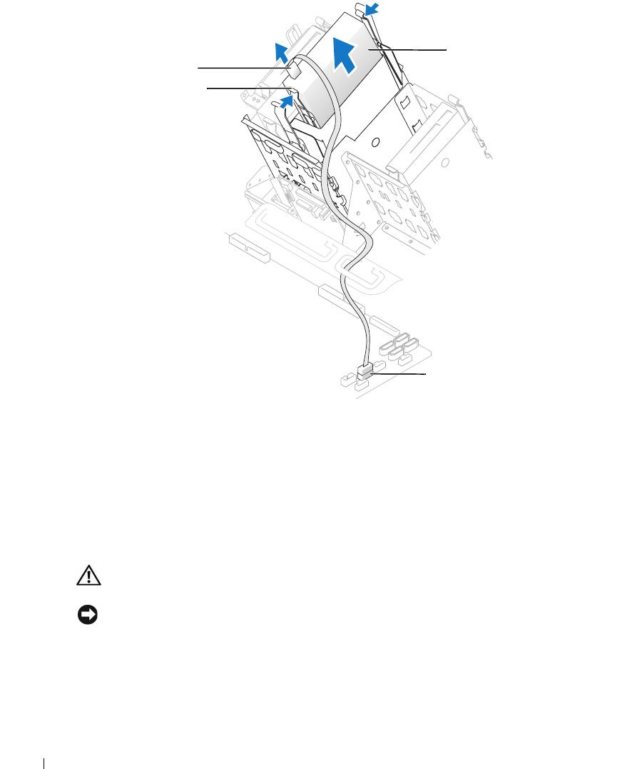
media card reader*
cable
tabs (2)
www.dell.com | support.dell.com
internal USB
connector
*
Not present on all computers.
4
Disconnect the USB cable on the back of the media card reader to the internal USB
connector on the system board.
5
Press in on the tabs on each side of the media card reader and slide the card reader out of the
adapter.
6
Close the computer (see "Closing the Computer Cover" on page 125).
Installing a Media Card Reader
CAUTION: Before you begin any of the procedures in this section, follow the safety instructions
located in the Product Information Guide.
NOTICE: To prevent static damage to components inside your computer, discharge static electricity
from your body before you touch any of your computer’s electronic components. You can do so by
touching an unpainted metal surface on the computer chassis.
1
Follow the procedures in "Before You Begin" on page 69.
2
Lay the computer on its side so that the system board is on the bottom of the inside of the
computer.
106 Removing and Installing Parts
3
Open the computer cover (see "Opening the Computer Cover" on page 76).
4
Remove the media card reader and bracket from its packaging.
5
Attach the adapter rails to the adapter by aligning the screw holes on the adapter with the
screw holes on the rails and then inserting and tightening all four screws (two on each rail).
adapter rails (2)
screws (4)
6
Slide the adapter into the 5.25-inch drive bay until the tabs on the rails securely click into
position.
Removing and Installing Parts 107
media card reader*
cable
tabs (2)
www.dell.com | support.dell.com
internal USB
connector
*
Not present on all computers.
7
Slide the media card reader into the adapter until the tabs on the rails securely click into
position.
8
Connect the internal USB cable to the media card reader
9
Route the USB cable through the cable routing clip.
10
Connect the internal USB cable to the internal USB connector on the system board.
11
Close the computer cover (see "Closing the Computer Cover" on page 125).
CD/DVD Drive
CAUTION: Before you begin any of the procedures in this section, follow the safety instructions
located in the Product Information Guide.
CAUTION: To guard against electrical shock, always unplug your computer from the electrical outlet
before opening the cover.
108 Removing and Installing Parts
Removing a CD/DVD Drive
1
Follow the procedures in "Before You Begin" on page 69.
2
Disconnect the power and data cables from the back of the drive.
power cable
tabs (2)
data cable
CD/DVD drive
3
Press inward on the two tabs on the sides of the drive, and then slide the drive upward and
remove it from the drive bay.
Removing and Installing Parts 109
Installing a CD/DVD Drive
1
Follow the procedures in "Before You Begin" on page 69.
2
If you are installing a new drive, unpack the drive and prepare it for installation.
Check the documentation that accompanied the drive to verify that the drive is configured
for your computer. If you are installing an IDE drive, configure the drive for the cable select
setting.
3
Connect the new drive to the set of rails that are attached to the inside of the cover. If a set of
rails is not attached inside the computer cover, contact Dell (see
"Contacting Dell" on
page 142
).
4
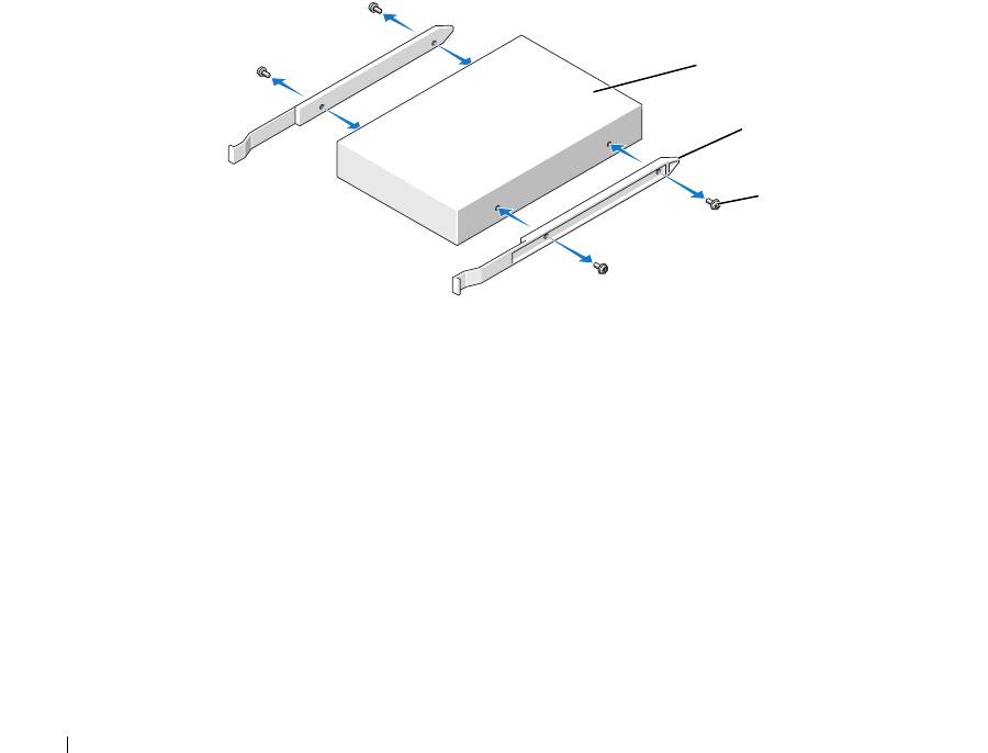
If you are installing a replacement drive and the new drive does not have the bracket rails
www.dell.com | support.dell.com
attached, remove the rails from the old drive by removing the two screws that secure each rail
to the drive. Attach the bracket to the new drive by aligning the screw holes on the drive with
the screw holes on the bracket rails and then inserting and tightening all four screws (two
screws on each rail).
drive
bracket rails (2)
screws (4)
5
Gently slide the drive into place until the tabs securely click into position.
6
Connect the power and data cables to the drive.
If you are adding a drive that has an audio cable, connect the audio cable to the audio
connector on the system board.
110 Removing and Installing Parts
power cable
tabs (2)
data cable
CD/DVD drive
7
Check all cable connections, and fold cables out of the way to provide airflow for the fan and
cooling vents.
8
Close the computer cover (see "Closing the Computer Cover" on page 125).
NOTICE: To connect a network cable, first plug the cable into the network port or device and then plug it
into the computer.
9
Connect your computer and devices to electrical outlets, and turn them on.
See the documentation that came with the drive for instructions on installing any software
required for drive operation.
10
Enter system setup (see "Entering System Setup" on page 131) and select the appropriate
Drive
option.
Removing and Installing Parts 111
11
Verify that your computer works correctly by running the Dell Diagnostics (see "Dell
Diagnostics" on page 58).
Processor Airflow Shroud
CAUTION: Before you perform this procedure, follow the safety instructions located in the Product
Information Guide.
CAUTION: To prevent static damage to components inside your computer, discharge static electricity
from your body before you touch any of your computer’s electronic components. You can do so by
touching an unpainted metal surface on the computer chassis.
NOTICE: To avoid damaging the fan power cables, do not slide the shroud too quickly.
www.dell.com | support.dell.com
Removing the Processor Airflow Shroud
1
Follow the procedures in "Before You Begin" on page 69.
2
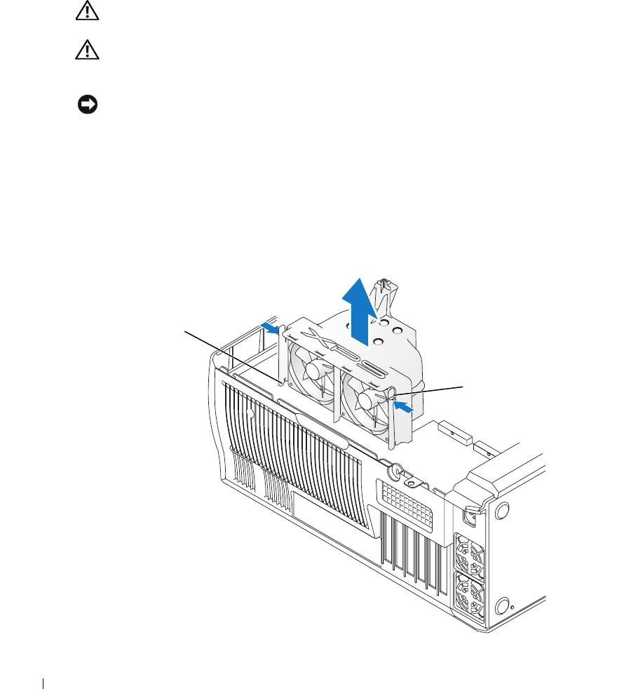
Press the two shroud release levers and lift the shroud up to disengage the anchors.
3
Once the shroud has been disengaged from the anchors, unplug the fan cables from their
connectors on the system board by pressing the release tabs on the fan cable connectors while
pulling up.
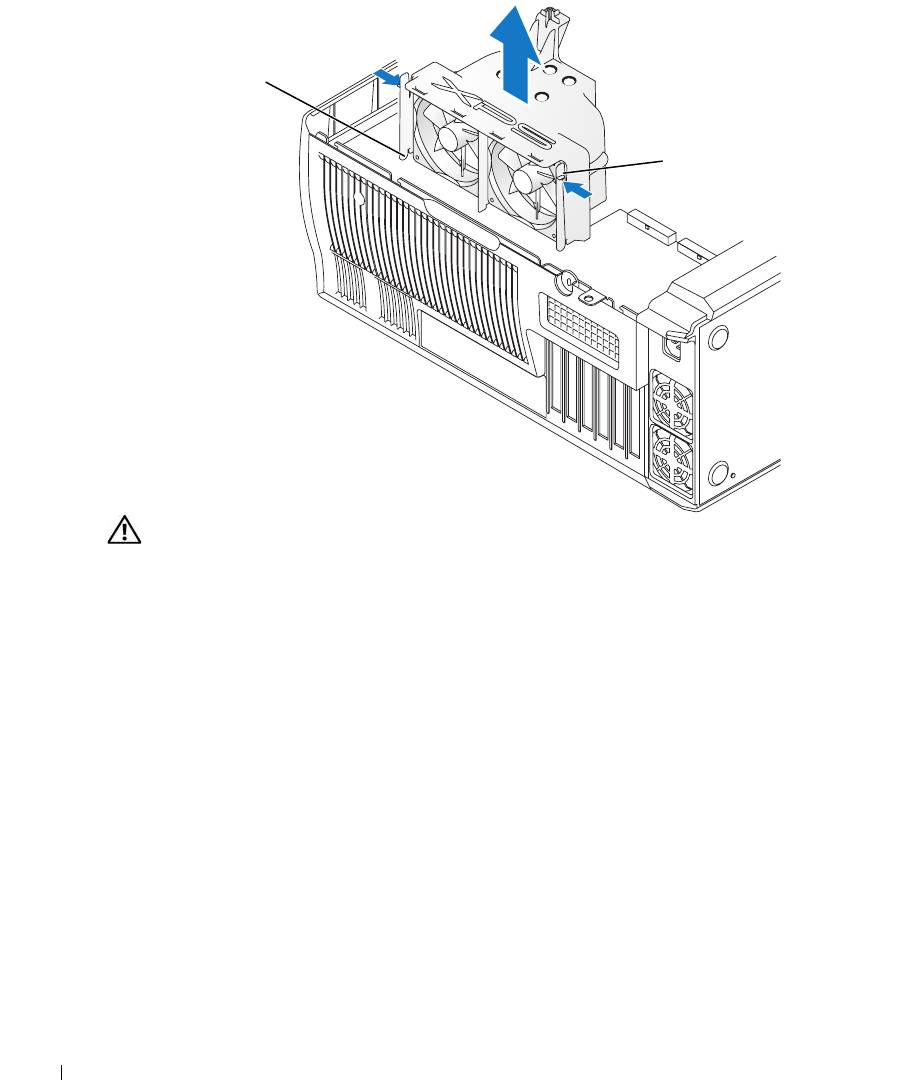
anchor tabs (3)
shroud release levers (2)
112 Removing and Installing Parts

Installing the Processor Airflow Shroud
1
Attach both fan power cables to the connectors on the system board.
2
Align the anchor tabs with the securing slots.
3
Gently press the shroud until the anchor tabs snap securely into place.
4
Close the computer cover.
NOTICE: To connect a network cable, first plug the cable into the network port or device and then plug it
into the computer.
5
Connect your computer and devices to electrical outlets, and turn them on.
Processor
NOTICE: Do not perform the following steps unless you are familiar with hardware removal and
replacement. Performing these steps incorrectly could damage your system board. For technical service,
see "Dell Technical Support Policy (U.S. Only)" on page 140.
CAUTION: Before you begin any of the procedures in this section, follow the safety instructions
located in the Product Information Guide.
Removing the Processor
1
Follow the procedures in "Before You Begin" on page 69.
2
Disconnect the two cooling fan power cables from the FANREAR and FANCPU connectors
(see "System Board Components" on page 78) on the system board.
3
Disconnect the power cable from the POWER12V connector (see "System Board
Components" on page 78) on the system board.
4
Remove the airflow shroud.
Removing and Installing Parts 113
anchor tabs (3)
shroud release levers (2)
www.dell.com | support.dell.com
CAUTION: The heat sink can get very hot during normal operation. Be sure that the heat sink has had
sufficient time to cool before you touch it.
114 Removing and Installing Parts
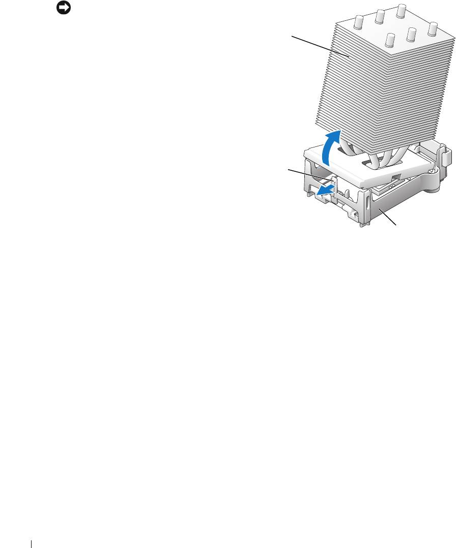
5
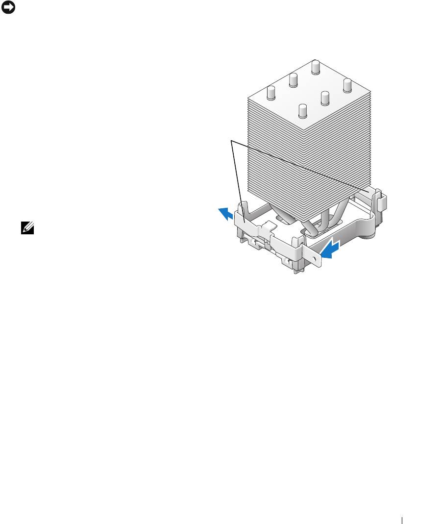
Remove the heat sink:
NOTICE: After the heat sink has been removed, lay the heat sink down on its side to avoid damaging the
thermal interface on the bottom.
a
Remove the retention module clip from the side of the retention base opposite the power
supply. Pull the tab on the clip straight out and away from the retention base to remove it.
b
On the retention base locate the
retention tab on the side opposite
the power supply, then press on
the tab, away from the heat sink
until the heat sink pops up
retention
slightly.
module clips
c
Rotate the heat sink back, then
slide it forward from beneath the
second retention tab and lift it
out of the retention base.
d
Remove the remaining retention
module clip, as needed.
NOTE: Removal of the remaining
retention module clip is not
necessary for removal of the
processor.
Removing and Installing Parts 115
NOTICE: If you are installing a processor
upgrade kit from Dell, discard the original
heat sink. If you are not installing a
heat sink
processor upgrade kit from Dell, reuse the
original heat sink and blower when you
install your new processor.
6
Push down and out on the socket
release lever.
www.dell.com | support.dell.com
retention tab
retention base
116 Removing and Installing Parts
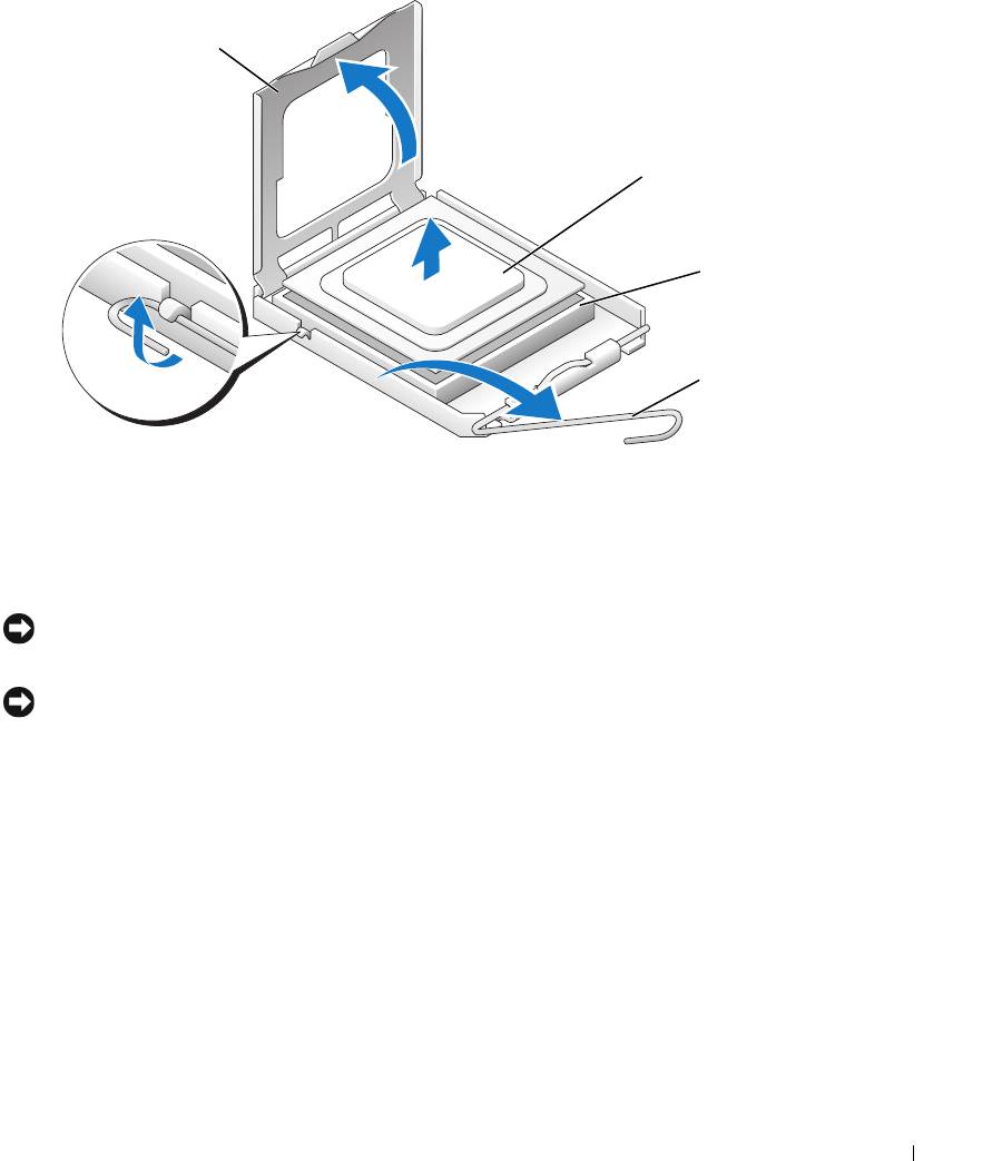
7
Open the processor cover.
processor cover
processor
socket
release lever
8
Remove the processor from the socket.
Leave the release lever extended in the release position so that the socket is ready for the new
processor.
Installing the Processor
NOTICE: Ground yourself by touching an unpainted metal surface on the back of the computer.
1
Unpack the new processor.
NOTICE: You must position the processor correctly in the socket to avoid permanent damage to the
processor and the computer when you turn on the computer.
2
If the release lever on the socket is not fully extended, move it to that position.
Removing and Installing Parts 117
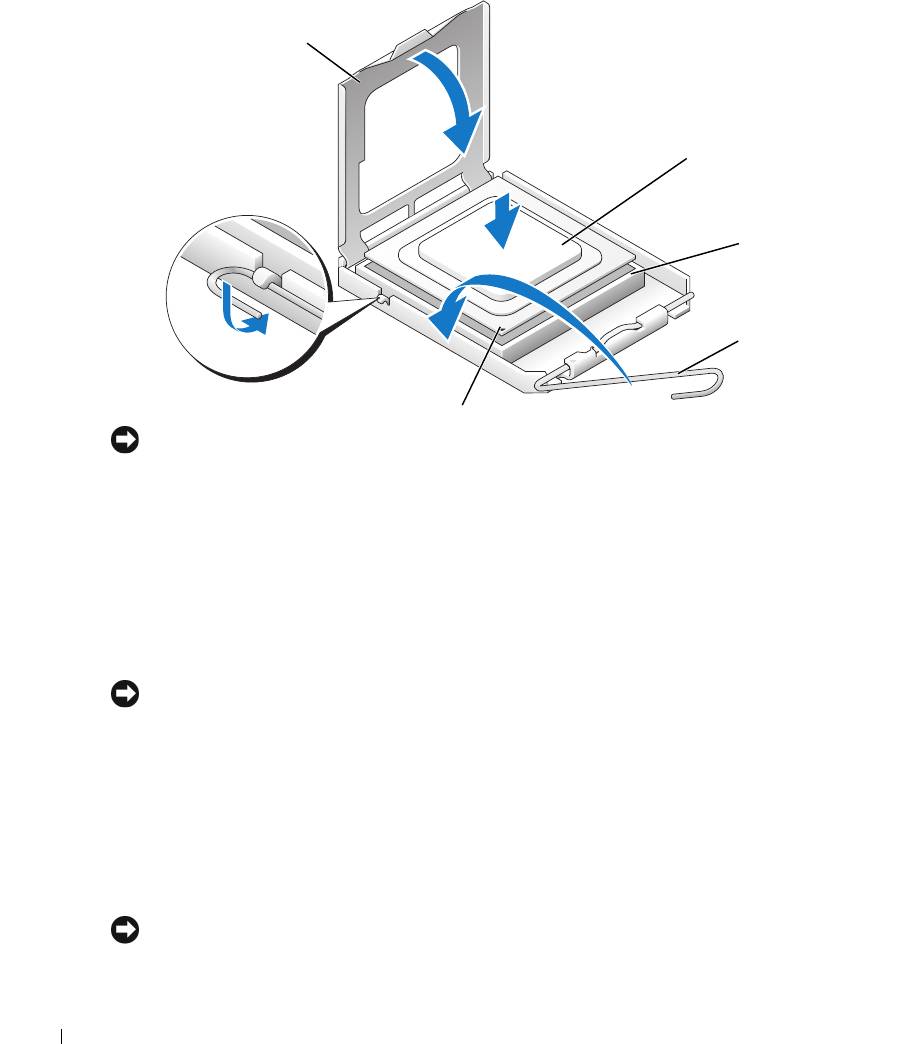
3
Align the pin-1 corner of the processor and socket.
processor cover
processor
www.dell.com | support.dell.com
socket
release lever
socket pin-1 indicator
NOTICE: Socket pins are delicate. To avoid damage, ensure that the processor is aligned properly with
the socket, and do not use excessive force when you install the processor. Be careful not to touch or
bend the pins on the system board.
4
Set the processor lightly in the socket and ensure that the processor is level in the socket.
When the processor is positioned correctly, press it with minimal pressure to seat it.
5 When the processor is fully seated in the socket, close the processor cover.
6 Pivot the socket release lever back toward the socket and snap it into place to secure the
processor.
7
Reinstall the retention module clip on the side closest to the processor fan, if necessary.
NOTICE: If you are not installing a processor upgrade kit from Dell, reuse the original heat sink assembly
when you replace the processor.
If you installed a processor replacement kit from Dell, return the original heat sink assembly
and processor to Dell in the same package in which your replacement kit was sent.
8
Install the heat sink:
a
Slide one end of the heat sink under the retention tab and the installed retention module
clip.
b
Pull out the other retention tab and lower the heat sink until it fits securely in the base.
NOTICE: Ensure that the heat sink is correctly seated and secure.
118 Removing and Installing Parts
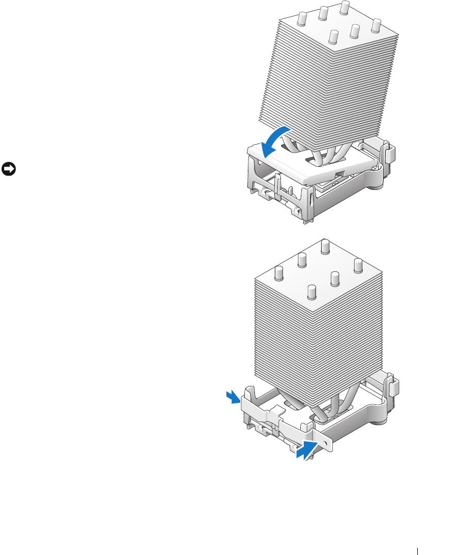
9
Reinstall the second retention module clip.
10
Lower the airflow shroud over the heat sink.
11
Reconnect the two cooling fan power cables to
the CPU FAN1 and CPU FAN2 connectors
(see "System Board Components" on page 78)
on the system board.
12
Reconnect the power cable to the POWER12V
connector (see "System Board Components" on
page 78) on the system board.
13
Close the computer cover (see "Closing the
Computer Cover" on page 125).
NOTICE: To connect a network cable, first plug the
cable into the network port or device and then plug it
into the computer.
14
Connect your computer and devices to
electrical outlets, and turn them on.
Removing and Installing Parts 119
Front Panel
CAUTION: To prevent static damage to components inside your computer, discharge static electricity
from your body before you touch any of your computer’s electronic components. You can do so by
touching an unpainted metal surface on the computer chassis.
CAUTION: Before you begin any of the procedures in this section, follow the safety instructions
located in the Product Information Guide.
Removing the Front Panel
1
Follow the procedures in "Before You Begin" on page 69.
2
Disconnect and remove all disk drives (see "Drives" on page 95).
www.dell.com | support.dell.com
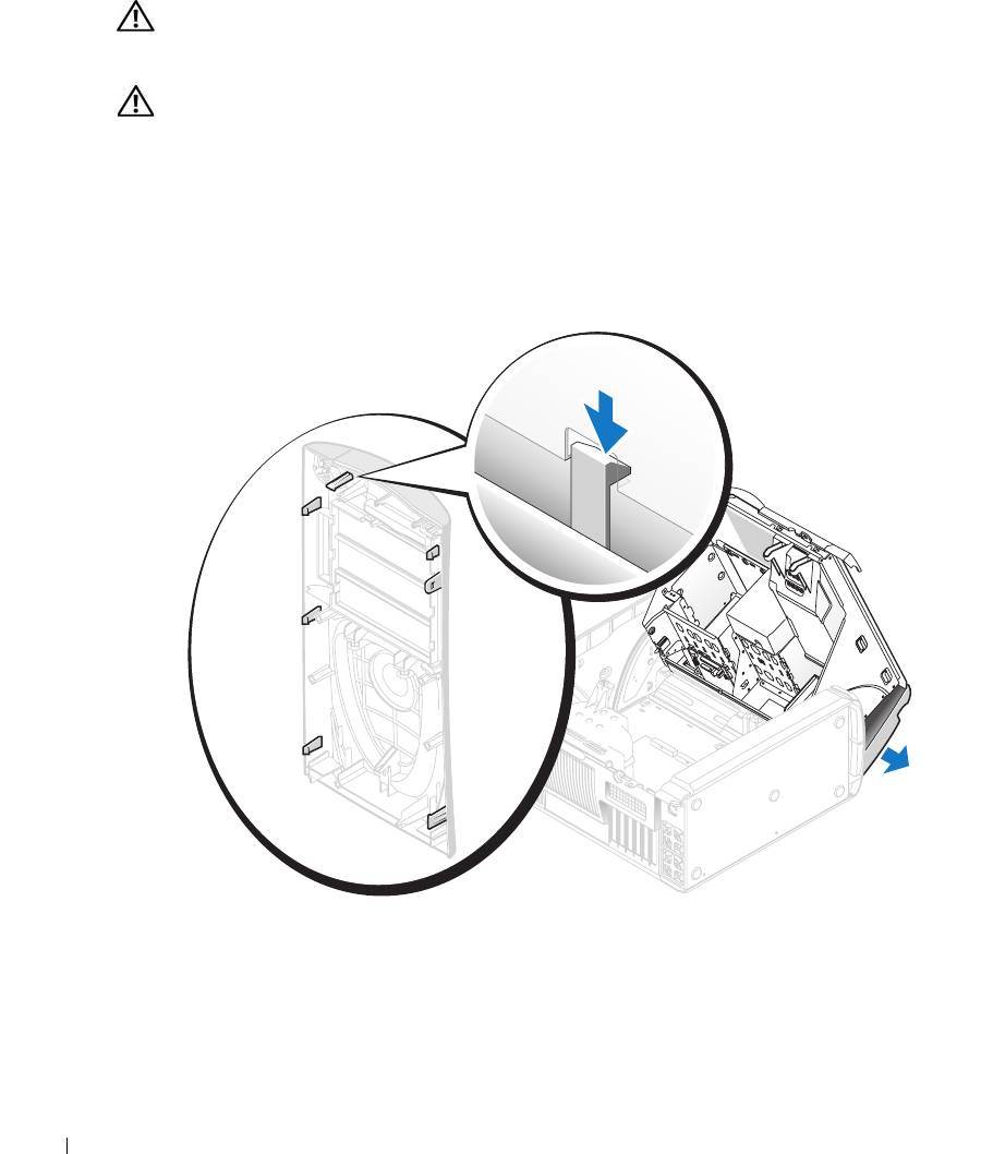
3
Release the front panel by pressing each of the seven front-panel release tabs.
4
Close the computer cover halfway and pull the front panel away from the computer.
Replacing the Front Panel
To replace the front panel, perform the
removal procedure
in reverse order.
120 Removing and Installing Parts
