Dell PowerVault MD3600i – страница 7
Инструкция к Компьютерным аксессуарам Dell PowerVault MD3600i
Оглавление
Drive Door
CAUTION: Before you begin any of the procedures in this section, follow the safety instructions
located in the Product Information Guide.
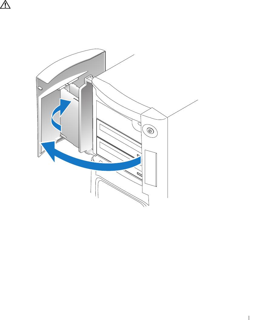
Removing the Drive Door
1
Open the drive door.
Removing and Installing Parts 121
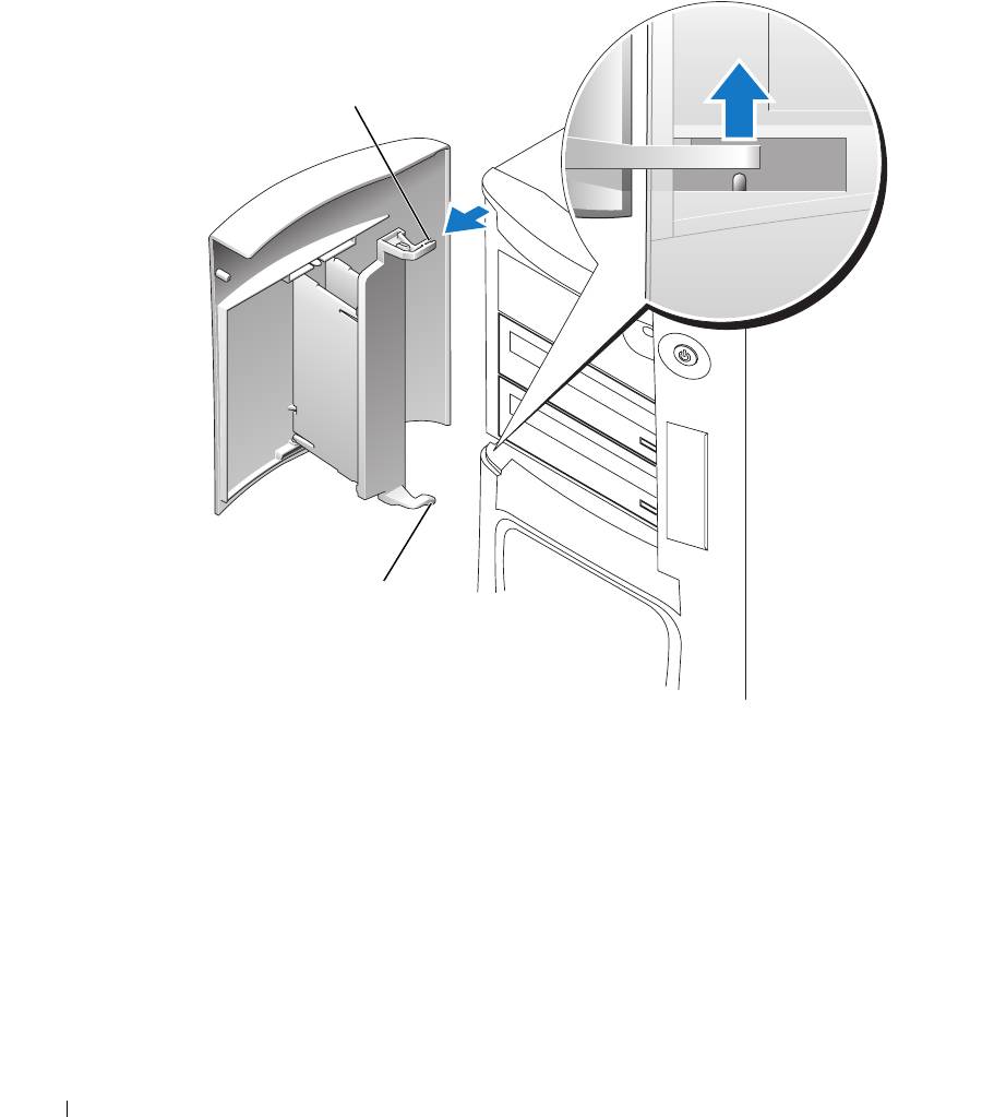
2
Unsnap the top bracket hinge and pull the top of the drive door outward, away from the
computer.
top bracket hinge
www.dell.com | support.dell.com
bottom bracket hinge
3
Lift the bottom bracket hinge away from the computer.
Replacing the Drive Door
To prevent damage to your computer, the drive door is designed to "break away" from the
computer if it is opened too far. If the drive door detaches from the computer without
disassembling, perform the removal procedure in reverse.
122 Removing and Installing Parts
If the drive door is open and it is opened too far, instead of breaking away from the computer in
one piece, the drive door may disassemble into several smaller pieces. If the drive door
disassembles:
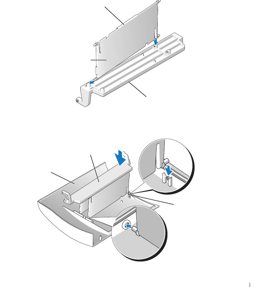
1
If necessary, reattach the door hinges to the door bracket. Ensure that the hinge tabs are away
from the door bracket.
hinge tab
door hinges (2)
door bracket
2
Attach the door bracket/door hinge assembly to the door, starting with the lower part of each
door hinge.
door bracket/door
hinge assembly
door
lower part of
the door hinge
3
Attach the drive door to the computer, starting with the bottom bracket hinge.
Removing and Installing Parts 123
Battery
CAUTION: Before you begin any of the procedures in this section, follow the safety instructions
located in the Product Information Guide.
NOTICE: To prevent static damage to components inside your computer, discharge static electricity
from your body before you touch any of your computer’s electronic components. You can do so by
touching an unpainted metal surface on the computer chassis.
Replacing the Battery
A coin-cell battery maintains computer configuration, date, and time information. The battery
can last several years.
www.dell.com | support.dell.com
If you have to repeatedly reset time and date information after turning on the computer, replace
the battery.
CAUTION: A new battery can explode if it is incorrectly installed. Replace the battery only with the
same or equivalent type recommended by the manufacturer. Discard used batteries according to the
manufacturer’s instructions.
To replace the battery:
1
Record all the screens in system setup (see "System Setup" on page 131) so that you can
restore the correct settings in step 8.
2
Follow the procedures in "Before You Begin" on page 69.
3
Locate the battery socket (see "System Board Components" on page 78).
NOTICE: If you pry the battery out of its socket with a blunt object, be careful not to touch the system
board with the object. Ensure that the object is inserted between the battery and the socket before you
attempt to pry out the battery. Otherwise, you may damage the system board by prying off the socket or
by breaking circuit traces on the system board.
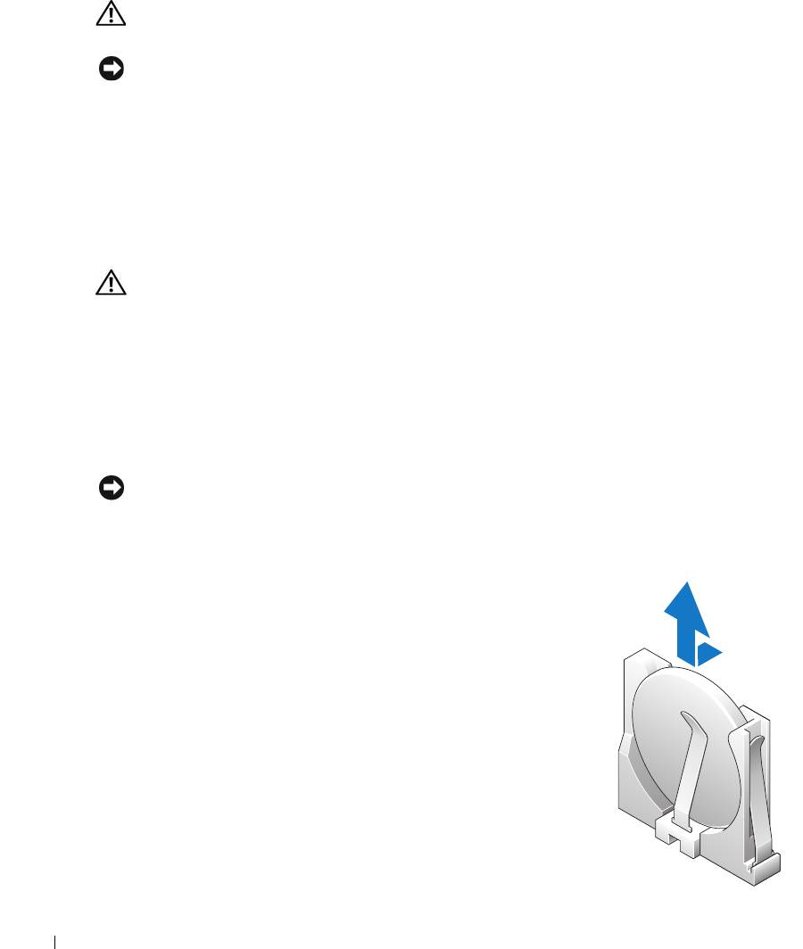
4
Remove the battery by prying it out of its socket with your
fingers.
5
Insert the new battery (CR2032) into the socket with the side
labeled "+" facing opposite the metal clip, and press the
battery into place.
6
Close the computer cover.
124 Removing and Installing Parts
NOTICE: To connect a network cable, first plug the cable into the network port or device and then plug it
into the computer.
7
Connect your computer and devices to electrical outlets, and turn them on.
8
Enter system setup (see "System Setup" on page 131) and restore the settings you recorded in
step 1.
9
Properly dispose of the old battery. See the
Product Information Guide
for battery disposal
information.
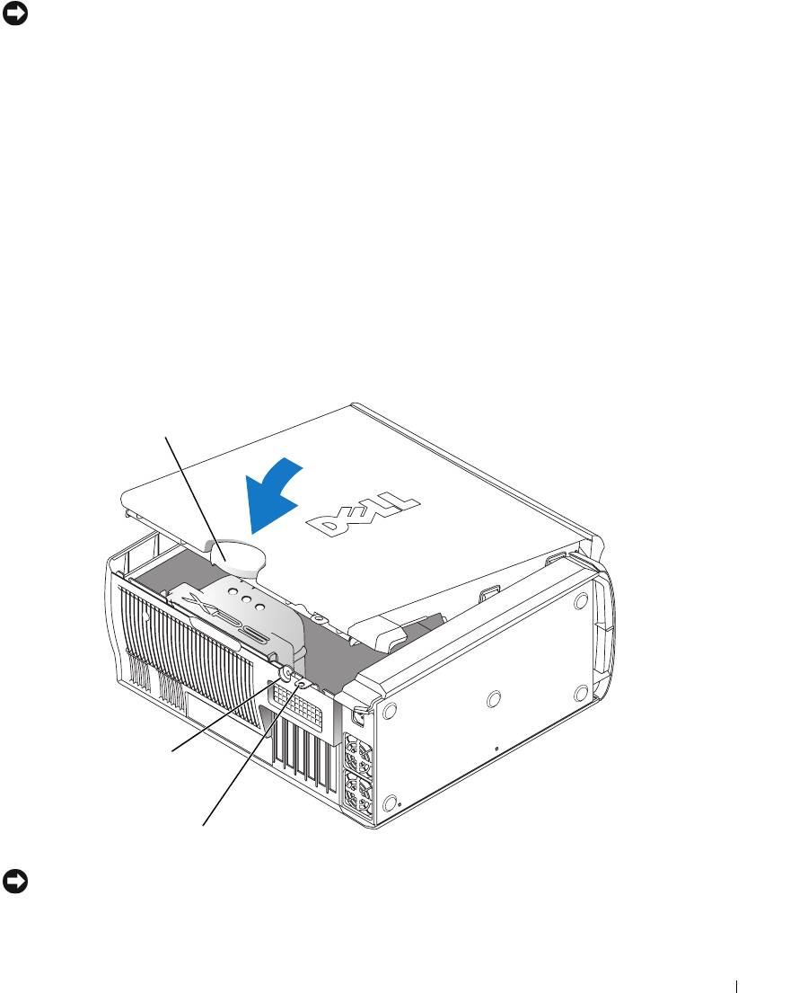
Closing the Computer Cover
1
Ensure that all cables are connected, and fold cables out of the way.
2
Ensure that no tools or extra parts are left inside the computer.
3
Pivot the cover down and into position.
4
Press down on the cover to close it.
5
Once the cover is closed, slide the release latch to the right until the latch clicks into place.
cover release
latch
security
cable slot
padlock ring
6
If you are using a padlock to secure your computer, install the padlock.
NOTICE: To connect a network cable, first plug the cable into the network port or device and then plug it
into the computer.
7
Connect your computer and devices to electrical outlets, and turn them on.
Removing and Installing Parts 125

www.dell.com | support.dell.com
126 Removing and Installing Parts

Appendix
Specifications
Processor
®
®
Processor type Intel
Pentium
4 Extreme Edition with HT Technology or dual-
core processing
NOTE: Not all Pentium 4 processors support Hyper-Threading
technology or dual-core processing.
Cache 1 MB or 2 MB
Memory
Type 533- and 667-MHz DDR2 unbuffered SDRAM
Memory connectors four
Memory capacities 256 MB, 512 MB, 1 GB, or 2 GB non-ECC
Minimum memory 512 MB
Maximum memory 2 GB or 8 GB
NOTE: See "Addressing Memory Configurations" on page 80 to verify
the amount of memory available to the operating system.
BIOS address F0000h
Computer Information
Chipset Nvidia nForce4 SLI X16 MCP
DMA channels five
Interrupt levels 24
BIOS chip (NVRAM) 4 Mb
NIC integrated network interface capable of 10/100/1000
communication.
System clock 800- or 1066-MHz data rate (depending on your processor)
Video
Type PCI Express
Appendix 127

Audio
Type AC97 7.1 channel
Expansion Bus
Bus type PCI 32-bit
PCI Express x1 and x16
Bus speed
PCI: 33 MHz
PCI Express: 2.5 Gb/s raw bandwidth (bidirectional) per lane
Bus throughput
PCI Express:
x1 slot bidirectional speed — 500 MB/s
www.dell.com | support.dell.com
x16 slot bidirectional speed — 8 GB/s
PCI
connector three
connector size 120 pins
connector data width (maximum) 32 bits
PCI Express
NOTE: If a graphics card is installed in each of the PCI Express x16
card slots in the dual-graphics configuration, the PCI Express x1 card
slot is not accessible for use.
connector one x1
connector size 36 pins
connector data width (maximum) 1 PCI Express lane
PCI Express
connector two x16
connector size 164 pins
connector data width (maximum) 16 PCI Express lanes
Drives
Externally accessible: one 3.5-inch drive bays
three 5.25-inch drive bays
Available devices Serial ATA drive, floppy drive, memory devices, CD drive, CD-RW
drive, DVD drive, DVD-RW drive, and DVD and CD-RW combo
drive, media card reader
Internally accessible:
three bays for 1-inch high hard drives
128 Appendix

Connectors
External connectors:
IEEE 1394 front and back-panel 6-pin serial connectors
Network adapter RJ45 connector
PS/2 (keyboard and mouse) two 6-pin mini-DIN
Serial 9-pin connector
USB two front-panel, six back-panel, and two internal USB 2.0–compliant
connectors
System board connectors:
IDE drive one 40-pin connector
Serial ATA four 7-pin connectors
Floppy drive 34-pin connector
Fan four 5-pin connectors
PCI three 120-pin connectors
PCI Express x1 36-pin connector
PCI Express x16 two 164-pin connectors
Controls and Lights
Power control push button
Power light green light — Blinking green in sleep state; solid green for power-on
state.
amber light — Blinking amber indicates a problem with an installed
device; solid amber indicates an internal power problem (see "Power
Problems" on page 49).
Hard-drive access light green
Link integrity light (on integrated
green light — A good connection exists between a 10-Mbps network
network adapter)
and the computer.
orange light
— A good connection exists between a 100-Mbps
network and the computer.
yellow light
— A good connection exists between a 1-GB
(or 1000-Mbps) network and the computer.
off (no light)
— The computer is not detecting a physical
connection to the network.
Activity light (on integrated network
yellow blinking light when there is activity on the network. If there is
adapter)
not any network activity, the light will be off.
Diagnostic lights four lights on the front panel (See "Diagnostic Lights" on page 55.)
Appendix 129

Controls and Lights (continued)
Standby power light AUXPWR on the system board
Case backlight color options: off (no light), ruby, emerald, sapphire (default), amber,
amethyst, topaz, diamond (See "Changing the Front-Panel Light
Color" on page 15.)
Power
650-W DC power supply:
Wattage 650 W
Heat dissipation 1000 BTU/hr
www.dell.com | support.dell.com
Voltage (see the safety instructions
fixed-voltage power supply — 110 V at 50/60 Hz
located in the
Product Information
manual selection and auto-sensing power supplies — 90 to 135 V
Guide
for important voltage setting
at 50/60 Hz; 180 to 265 V at 50/60 Hz; 100 V at 50/60 Hz for
information)
Japanese computers
Backup battery 3-V CR2032 lithium coin cell
Physical
Height 49.1 cm (19.3 inches)
Width 22.2 cm (8.7 inches)
Depth 48.8 cm (19.2 inches)
Weight 19 kg (42 lb)
Environmental
Temperature:
Operating 10° to 35°C (50° to 95°F)
Storage –40° to 65°C (–40° to 149°F)
Relative humidity 20% to 80% (noncondensing)
Maximum vibration:
Operating 0.25 G at 3 to 200 Hz at 0.5 octave/min
Storage 0.5 G at 3 to 200 Hz at 1 octave/min
Maximum shock:
Operating bottom half-sine pulse with a change in velocity of 20 inches/sec
(50.8 cm/sec)
Storage 27-G faired square wave with a velocity change of 200 inches/sec
(508 cm/sec)
130 Appendix

Environmental (continued)
Altitude:
Operating –15.2 to 3048 m (–50 to 10,000 ft)
Storage –15.2 to 10,668 m (–50 to 35,000 ft)
System Setup
Overview
Use system setup as follows:
• To change the system configuration information after you add, change, or remove any
hardware in your computer
• To set or change a user-selectable option such as the user password
• To read the current amount of memory or set the type of hard drive installed
Before you use system setup, it is recommended that you write down the system setup screen
information for future reference.
NOTICE: Unless you are an expert computer user, do not change the settings for this program. Certain
changes can make your computer work incorrectly.
Entering System Setup
1
Turn on (or restart) your computer.
2
When the blue DELL™ logo appears, press <F2> immediately.
If you wait too long and the operating system logo appears, continue to wait until you see the
®
®
Microsoft
Windows
desktop. Then shut down your computer (see "Turning Off Your
Computer" on page 69) and try again.
System Setup Screens
The system setup screen displays current or changeable configuration information for your
computer. Information on the screen is divided into three areas: the options list, the active
options field, and key functions.
Appendix 131
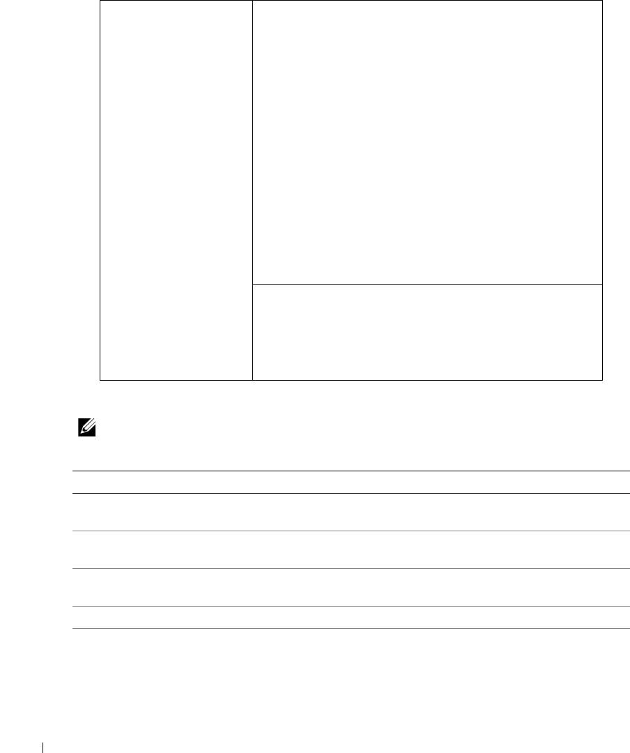
Options List — This
Option Field — This field contains information about
field appears on the left
each option. In this field you can view your current settings
side of the system setup
and make changes to your settings.
window. The field is a
Press the left- and right-arrow keys to highlight an option.
scrollable list containing
Press <Enter> to make that selection active.
features that define the
configuration of your
computer, including
installed hardware,
power conservation, and
security features.
www.dell.com | support.dell.com
Scroll up and down the
list with the up- and
down-arrow keys. As an
option is highlighted,
the Option Field
Key Functions — This field appears below the Option
displays more
Field and lists keys and their functions within the active
information about that
system setup field.
option and the option’s
current and available
settings.
System Setup Options
NOTE: Depending on your computer and installed devices, the items listed in this section may not
appear, or may not appear exactly as listed.
System
System Info Lists system information such as the computer name, the BIOS version
number and date, system tags, and other system-specific information.
CPU Info Identifies whether the computer’s processor supports Hyper-Threading and
lists the processor bus speed, processor ID, clock speed, and L2 cache.
Memory Info Indicates amount of installed memory, memory speed, channel mode (dual
or single), and type of memory installed.
PCI Info Indicates the expansion card type by slot location.
Date/Time Displays current date and time settings.
132 Appendix

Boot Sequence The computer attempts to boot from the sequence of devices specified in
this list.
NOTE: If you insert a boot device and restart the computer, this option appears
in the system setup menu. To boot from a USB memory device, select the USB
device and move it so it becomes the first device in the list.
Drives
Diskette Drive Identifies and defines the floppy drive attached to the DSKT connector on
the system board as Off, USB, Internal, or Read Only.
SATA Drives 0
Identifies and defines the SATA drive settings. You can set the SATA drive
through 3
to On, Off, or RAID On. The default setting is On.
PATA Drives 0
Identifies the drives attached to the ATA connectors on the system board,
through 1
and lists the capacity for hard drives.
Smart Reporting
Determines whether hard-drive errors for internal drives are reported during
system startup.
Off
does not report errors.
On
reports errors.
Onboard Devices
Integrated NIC
Enables or disables the integrated NIC controller.
Off
disables the controller.
On
enables the controller.
NOTE:
PXE and RPL is required only if you are booting to an operating system
on another system; not if you are booting to an operating system on a hard
drive in this system.
Audio Controller Enables or disables the onboard audio controller.
USB Controller (Default On) Enables or disables the internal USB controller. Off disables
the controller. On enables the controller. No Boot enables the controller but
disables the ability to boot from a USB device.
1394 Controller Enables or disables the IEEE 1394 controller.
Serial Port #1 Disables or selects the address for the serial port. Options consist of: Off,
Auto (which selects the port automatically and disables it if both addresses
are in use), COM1 and COM3.
PS/2 Mouse Port Enables or disables the onboard PS/2-compatible mouse controller.
Front LED Color This setting allows you to change the front-panel back lighting to the
following colors: off, ruby, emerald, amber, sapphire, amethyst, topaz, and
diamond.
Video
Primary Video This setting specifies which video controller is primary when two video
controllers are present on the computer.
Performance
Hyper-Threading If your processor supports Hyper-Threading, this option appears in the
Options List.
Appendix 133

Multiple CPU Core This setting specifies whether more than one core is enabled. The
performance of some applications may improve with an additional core
enabled. Defaults to On (second core enabled).
HDD Acoustic Mode
•
Bypass
— Your computer does not test or change the current acoustics
mode setting.
•
Quiet
(default) — The hard drive operates at its most quiet setting.
•
Suggested
— The hard drive operates at the level suggested by the drive
manufacturer.
•
Performance
—
The hard drive operates at its maximum speed.
NOTE: Switching to performance mode may cause the drive to be noisier, but
its performance is not affected.
NOTE: Changing the acoustics setting does not alter your hard drive image.
www.dell.com | support.dell.com
CPU Clock Speed With this option, it is possible to increase the operating frequency of the
processor to a frequency greater than that in the processor manufacturer’s
design specifications. Use of this option may invalidate your warranty.
NOTICE: Dell does not recommend using extended operating
frequencies or over-clocking. If you choose to over-clock your
processor, the life expectancy of your processor may be reduced. Dell
does not guarantee that your computer will remain stable or operate at
the extended operating speeds.
Security This section displays available system security options.
Admin Password This option provides restricted access to the computer's system setup
program in the same way that access to the system can be restricted with the
System Password option.
System Password Displays the current status of the system's password security feature and
allows a new system password to be assigned and verified.
Password Changes This option locks the system password field with the setup password. When
the field is locked, you can no longer disable password security by pressing
<Ctrl><Enter> when the computer starts.
DEP (Execute
•
Opt-In
(default) — DEP is enabled by default on computers with
Disable)
NX-capable processors. Only Windows system binaries are covered by DEP
with this option. Applications may enable DEP protection through creating
an application compatibility shim and installing that shim with the
application.
•
Opt-Out
— DEP is enabled for all processes. Users can manually create
exceptions for specific applications in System Properties, or IT Pros and
ISVs can use the Application Compatibility Toolkit to opt-out.
•
Always On
— Full DEP coverage with no exceptions.
•
Always Off
—
No user-mode DEP coverage. Drivers and the Widows core
kernel binaries are covered by DEP, but no other binaries are included in the
set of covered applications.
134 Appendix

Power Management
AC Recovery Determines what happens when AC power is restored to the computer.
Auto Power On Sets the computer to automatically turn on. Choices are every day or every
Monday through Friday.
The default setting is Off.
This feature does not work if you turn off your computer using a power strip
or surge protector.
Auto Power Time Sets time to automatically turn on the computer.
Time is kept in a 24-hour format (hours:minutes). Change the start-up time
by pressing the right- or left-arrow key to increase or decrease the numbers,
or type numbers in both the date and time fields.
This feature does not work if you turn off your computer using a power strip
or surge protector.
Suspend Mode The options are S1, a suspend state where the computer is running in a low-
power mode, and S3, a standby state where the power is reduced or turned
off for most components, however, system memory remains active.
Maintenance
Load Defaults This setting restores the computer’s factory-installed default settings.
Event Log Displays the system event log.
POST Behavior
Fastboot When set to On (default), your computer starts more quickly because it
skips certain configurations and tests.
Numlock Key This option involves the rightmost bank of keys on your keyboard. When set
to On (default), this option activates the numeric and mathematical
features shown at the top of each key. When set to Off, this option activates
the cursor-control functions labeled on the bottom of each key.
POST Hotkeys This option allows you to specify the function keys to display on the screen
when the computer starts.
Keyboard Errors This option disables or enables keyboard error reporting when the computer
starts.
Appendix 135

Boot Sequence
This feature allows you to change the boot sequence for devices.
Option Settings
•
Diskette Drive —
The computer attempts to boot from the floppy drive. If the floppy disk in the
drive is not bootable, if no floppy disk is in the drive, or if there is no floppy drive installed in the
computer, the computer attempts to boot from the next bootable device in the boot sequence.
•
Hard Drive
— The computer attempts to boot from the primary hard drive. If no operating
system is on the drive, the computer attempts to boot from the next bootable device in the
boot sequence.
•
CD Drive
— The computer attempts to boot from the CD drive. If no CD is in the drive, or
www.dell.com | support.dell.com
if the CD has no operating system, the computer attempts to boot from the next bootable
device in the boot sequence.
•
USB Flash Device —
Insert the memory device into a USB port and restart the computer.
When
F12 = Boot Menu
appears in the upper-right corner of the screen, press <F12>. The
BIOS detects the device and adds the USB flash option to the boot menu.
NOTE: To boot to a USB device, the device must be bootable. To make sure that your device is bootable,
check the device documentation.
NOTE: An error message is generated only after the computer attempts to boot from every device in the
boot sequence and no operating system is found.
Changing Boot Sequence for the Current Boot
You can use this feature, for example, to tell the computer to boot from the CD drive so that
you can run the Dell Diagnostics on the Dell ResourceCD, but you want the computer to boot
from the hard drive when the diagnostic tests are complete. You can also use this feature to
restart your computer to a USB device such as a floppy drive, memory key, or CD-RW drive.
NOTE: If you are booting to a USB floppy drive, you must first set the floppy drive to OFF in system setup
(see "System Setup" on page 131).
1
If you are booting to a USB device, connect the USB device to a USB connector (see "Front
View (Doors Open)" on page 72).
2
Turn on (or restart) your computer.
3
When
F2 = Setup, F12 = Boot Menu
appears in the upper-right corner of the screen,
press <F12>.
If you wait too long and the operating system logo appears, continue to wait until you see the
Microsoft Windows desktop. Then shut down your computer (see "Turning Off Your
Computer" on page 69) and try again.
The
Boot Device Menu
appears, listing all available boot devices. Each device has a number
next to it.
136 Appendix
4
At the bottom of the menu, enter the number of the device that is to be used for the current
boot only.
For example, if you are booting to a USB memory key, highlight
USB Flash Device
and press
<Enter>.
NOTE: To boot to a USB device, the device must be bootable. To make sure that your device is bootable,
check the device documentation.
Changing Boot Sequence for Future Boots
1
Enter system setup (see "Entering System Setup" on page 131).
2
Use the arrow keys to highlight the
Boot Sequence
menu option and press <Enter> to access
the menu.
NOTE: Write down your current boot sequence in case you want to restore it.
3
Press the up- and down-arrow keys to move through the list of devices.
4
Press the spacebar to enable or disable a device (enabled devices have a checkmark).
5
Press plus (+) or minus (–) to move a selected device up or down the list.
Clearing Forgotten Passwords
CAUTION: Before you begin any of the procedures in this section, follow the safety instructions
located in the Product Information Guide.
1
Follow the procedures in "Before You Begin" on page 69.
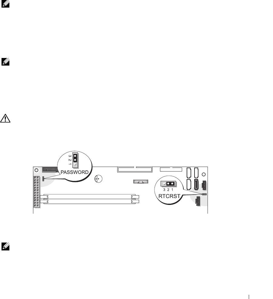
2
Locate the 3-pin password jumper (PASSWORD) on the system board (see "System Board
Components" on page 78), and attach the jumper plug to pins 2 and 3 to clear the password.
NOTE: When you receive your computer, the jumper plug is attached to pins 1 and 2.
3
Close the computer cover.
4
Connect your computer and monitor to electrical outlets, and turn them on.
Appendix 137

®
®
5
After the Microsoft
Windows
desktop appears on your computer, shut down the computer
(see "Turning Off Your Computer" on page 69).
6
Turn off the monitor and disconnect it from the electrical outlet.
7
Disconnect the computer power cable from the electrical outlet, and press the power button
to ground the system board.
8
Open the computer cover (see "Opening the Computer Cover" on page 76).
9
Locate the 3-pin password jumper on the system board (see "System Board Components" on
page 78) and attach the jumper to pins 1 and 2 to reenable the password feature.
10
Replace the computer cover (see "Closing the Computer Cover" on page 125).
NOTICE: To connect a network cable, first plug the cable into the network wall jack and then plug it into
www.dell.com | support.dell.com
the computer.
11
Connect your computer and devices to electrical outlets, and turn them on.
Clearing CMOS Settings
CAUTION: Before you begin any of the procedures in this section, follow the safety instructions
located in the Product Information Guide.
1
Follow the procedures in "Before You Begin" on page 69.
2
Reset the current CMOS settings:
a
Locate the 3-pin CMOS jumper (RTCRST) on the system board (see "System Board
Components" on page 78).
b
Remove the jumper plug from pins 1 and 2.
c
Place the jumper plug on pins 2 and 3 and wait approximately 5 seconds.
d
Replace the jumper plug on pins 1 and 2.
3
Close the computer cover (see "Closing the Computer Cover" on page 125).
NOTICE: To connect a network cable, first plug the cable into the network wall jack and then plug it into
the computer.
4
Connect your computer and devices to electrical outlets, and turn them on.
138 Appendix

Cleaning Your Computer
CAUTION: Before you begin any of the procedures in this section, follow the safety instructions
located in the Product Information Guide.
Computer, Keyboard, and Monitor
CAUTION: Before you clean your computer, disconnect the computer from the electrical outlet. Clean
your computer with a soft cloth dampened with water. Do not use liquid or aerosol cleaners, which may
contain flammable substances.
• Use a vacuum cleaner with a brush attachment to gently remove dust from the slots and holes
on your computer and from between the keys on the keyboard.
NOTICE: Do not wipe the display screen with any soap or alcohol solution. Doing so may damage the
antiglare coating.
• To clean your monitor screen, lightly dampen a soft, clean cloth with water. If possible, use a
special screen-cleaning tissue or solution suitable for the monitor’s antistatic coating.
• Wipe the keyboard, computer, and plastic part of the monitor with a soft cleaning cloth
moistened with a solution of three parts water and one part dishwashing detergent.
Do not soak the cloth or let water drip inside your computer or keyboard.
Mouse
If your screen cursor skips or moves abnormally, clean the mouse. To clean a non-optical mouse:
1
Turn the retainer ring on the underside of your mouse counterclockwise, and then remove the
ball.
2
Wipe the ball with a clean, lint-free cloth.
3
Blow carefully into the ball cage to dislodge dust and lint.
4
If the rollers inside the ball cage are dirty, clean the rollers with a cotton swab moistened
lightly with isopropyl alcohol.
5
Recenter the rollers in their channels if they are misaligned. Ensure that fluff from the swab is
not left on the rollers.
6
Replace the ball and retainer ring, and turn the retainer ring clockwise until it clicks into
place.
Floppy Drive
NOTICE: Do not attempt to clean drive heads with a swab. You might accidentally misalign the heads,
which prevents the drive from operating.
Clean your floppy drive using a commercially available cleaning kit. These kits contain
pretreated floppy disks to remove contaminants that accumulate during normal operation.
Appendix 139

CDs and DVDs
NOTICE: Always use compressed air to clean the lens in the CD/DVD drive, and follow the instructions
that come with the compressed air. Never touch the lens in the drive.
If you notice problems, such as skipping, with the playback quality of your CDs or DVDs, try
cleaning the discs.
1
Hold the disc by its outer edge. You can also touch the inside edge of the center hole.
NOTICE: To prevent damaging the surface, do not wipe in a circular motion around the disc.
2
With a soft, lint-free cloth, gently wipe the bottom of the disc (the unlabeled side) in a
straight line from the center to the outer edge of the disc.
For stubborn dirt, try using water or a diluted solution of water and mild soap. You can also
www.dell.com | support.dell.com
purchase commercial products that clean discs and provide some protection from dust,
fingerprints, and scratches. Cleaning products for CDs are safe to use on DVDs.
Dell Technical Support Policy (U.S. Only)
Technician-assisted technical support requires the cooperation and participation of the
customer in the troubleshooting process and provides for restoration of the operating system,
software programs, and hardware drivers to the original default configuration as shipped from
Dell, as well as the verification of appropriate functionality of the computer and all Dell-
installed hardware. In addition to this technician-assisted technical support, online technical
support is available at support.dell.com. Additional technical support options may be available
for purchase.
Dell provides limited technical support for the computer and any "Dell-installed" software and
1
peripherals
. Support for third-party software and peripherals is provided by the original
manufacturer, including those purchased and/or installed through Dell Software and
2
Peripherals, Readyware, and Custom Factory Integration
.
1
Repair services are provided pursuant to the terms and conditions of your limited warranty and any optional
support service contract purchased with the computer.
2
All Dell-standard components included in a Custom Factory Integration (CFI) project are covered by the stan-
dard Dell limited warranty for your computer. However, Dell also extends a parts replacement program to
cover all nonstandard, third-party hardware components integrated through CFI for the duration of the com-
puter’s service contract.
Definition of "Dell-Installed" Software and Peripherals
Dell-installed software includes the operating system and some of the software programs that
®
are installed on the computer during the manufacturing process (Microsoft
Office, Norton
Antivirus, and so on).
140 Appendix
