Dell POWEREDGE M1000E – страница 3
Инструкция к Компьютерным аксессуарам Dell POWEREDGE M1000E
Оглавление

book.book Page 41 Wednesday, March 9, 2011 3:11 PM
Table 2-2. Cabling Requirements for External Digital KVM Switches
Switch Tiering Requirements
Dell PowerConnect 2161DS,
Seamless tiering using ACI port
4161DS, 2161DS-2, 2321DS
and Cat 5 cable
(version 1.3.40.0 or later)
Avocent DSR x02x (except 1024),
x03x (version 3.6 or later)
Avocent DSR 800, x16x, x010,
Avocent USB SIP (DSRIQ-USB)
1024
required with Cat 5 cable
To tier the iKVM module from a Dell 2161DS, 180AS, or 2160AS console
switch:
•
If the switch does not require a SIP to connect to the iKVM (see
Ta b le 2 - 2
)
,
connect a Cat5 (or newer) cable to the RJ-45 ACI port on the iKVM
module. See Figure 1-16.
Connect the other end of this cable to the ARI port on the external switch.
•
If the switch requires a USB SIP (see Table 2-1)
, connect an Avocent USB
SIP
to the iKVM, then connect a Cat5 (or newer) cable to the
SIP
. Connect
the other end of this cable to the ARI port on the external switch.
Once the KVM switch is connected, the server modules appear in OSCAR.
NOTE: When the local system is set up, you must also resynchronize the server list
from the Remote Console Switch software in order to see the list of blades. See
"Resynchronizing the Server List at the Remote Client Workstation" on page 42.
Viewing and Selecting Servers
Use the OSCAR Main dialog box to view, configure, and manage servers in
the M1000e enclosure through the iKVM. You can view the servers by name
or by slot. The slot number is the chassis slot number the server occupies. The
Slot column indicates the slot number in which a server is installed.
NOTE: Server names and slot numbers are assigned by the CMC.
NOTE: If you have enabled access to the CMC though the iKVM, an additional
option, Dell CMC Console, is displayed. To enable this feature, see "Enabling iKVM
Access to the Dell CMC Console" on page 38.
Initial System Configuration 41

book.book Page 42 Wednesday, March 9, 2011 3:11 PM
To access the Main dialog box:
Press <Print Screen> to launch the OSCAR interface. The
Main dialog box
is
displayed
.
or
If a password has been assigned, the Password dialog box
is displayed
. Type
your password and click OK. The
Main dialog box
is displayed
.
Resynchronizing the Server List at the Remote Client Workstation
Once the iKVM module is connected, the blades appear in OSCAR. You now
need to resynchronize the servers on any remote workstation to ensure that
the blades are available to any remote users connected to the console switch
through the Remote Console Switch software.
NOTE: This procedure only resynchronizes one remote client workstation. With
multiple client workstations, save the resynchronized local database and load it into
the other client workstations to ensure consistency.
To resynchronize the server listing:
1
Click
Resync
in the
Server
category of the Management Panel (MP).
The Resync Wizard launches.
2
Click
Next
.
A warning message appears indicating that the database will be updated to
match the current configuration of the console switch. Your current local
database names will be overwritten with the switch names. To include
unpowered SIPs in the resynchronization, click to enable the
Include
Offline SIPs
check box.
3
Click
Next
.
A
Polling Remote Console Switch
message box appears with a progress
bar indicating that the switch information is being retrieved.
4
If no changes were detected in the appliance, a completion dialog box
appears with this information.
If server changes were detected, then the
Detected Changes
dialog box is
displayed. Click
Next
to update the database.
5
If a cascade switch was detected, the
Enter Cascade Switch Information
dialog box is displayed.
42 Initial System Configuration

book.book Page 43 Wednesday, March 9, 2011 3:11 PM
6
Select the type of switch connected to the appliance from the drop-down
list. If the type you are looking for is not available, you can add it by
clicking
Add
.
7
Click
Next
. The completion dialog box is displayed.
8
Click
Finish
to exit.
9
Start up the analog switch and the system.
FlexAddress
The FlexAddress feature is an optional upgrade introduced in CMC 1.1 that
allows server modules to replace the factory assigned World Wide Name and
Media Access Control (WWN/MAC) network IDs with WWN/MAC IDs
provided by the chassis.
Every server module is assigned unique WWN and MAC IDs as part of the
manufacturing process. Before the FlexAddress feature was introduced, if you
had to replace one server module with another, the WWN/MAC IDs would
change and Ethernet network management tools and SAN resources would
need to be reconfigured to be aware of the new server module.
FlexAddress allows the CMC to assign WWN/MAC IDs to a particular slot
and override the factory IDs. If the server module is replaced, the slot-based
WWN/MAC ID remains the same. This feature eliminates the need to
reconfigure Ethernet network management tools and SAN resources for a new
server module.
Additionally, the override action only occurs when a server module is inserted
in a FlexAddress enabled chassis; no permanent changes are made to the
server module. If a server module is moved to a chassis that does not support
FlexAddress, the factory assigned WWN/MAC IDs are used.
Prior to installing FlexAddress, you can determine the range of MAC
addresses contained on a FlexAddress feature card by inserting the SD card
into an USB Memory Card Reader and viewing the file pwwn_mac.xml. This
clear text XML file on the SD card contains an XML tag mac_start, which is
the first starting hex MAC address that will be used for this unique MAC
address range. The mac_count tag is the total number of MAC addresses that
the SD card allocates. The total MAC range allocated can be determined by:
<mac_start> + 0xCF (208 - 1) = mac_end
Initial System Configuration 43

book.book Page 44 Wednesday, March 9, 2011 3:11 PM
For example:(starting_mac)00188BFFDCFA + 0xCF =
(ending_mac)00188BFFDDC9
NOTE: You must lock the SD card prior to inserting in the USB "Memory Card
Reader" to prevent accidently modifying any of the contents. You must unlock the
SD card before inserting into the CMC.
FlexAddress Plus
The FlexAddress Plus is a new feature added to the feature card version 2.0.
FlexAddress Plus expands the number of MAC addresses to 3136 from the
original FlexAddress pool of 208.
Activating FlexAddress
FlexAddress is delivered on a Secure Digital (SD) card that must be inserted
into the CMC to provide the chassis-assigned WWN/MAC IDs. To activate
the FlexAddress feature, perform several required updates; if you are not
activating FlexAddress, these updates are not required. The updates, which
are listed in the following table, include server module BIOS, I/O mezzanine
BIOS or firmware, and CMC firmware. You must apply these updates before
you enable FlexAddress. If these updates are not applied, the FlexAddress
feature may not function as expected.
NOTE: All systems purchased after June 2008 have the correct firmware versions
installed.
Component Minimum Required Version
Ethernet mezzanine card - Broadcom
Boot code firmware 4.4.1 or later
M5708t
iSCSI boot firmware 2.7.11 or later
PXE firmware 4.4.3 or later
FC mezzanine card - QLogic QME2472 BIOS 2.04 or later
FC mezzanine card - Emulex LPe1105-
BIOS 3.03a3 and firmware 2.72A2 or
M4
later
Server Module BIOS (PowerEdge M600) BIOS 2.02 or later
(PowerEdge M605) BIOS 2.03 or later
PowerEdge M600/M605 LAN on
Boot code firmware 4.4.1 or later
motherboard (LOM)
iSCSI boot firmware 2.7.11 or later
iDRAC Version 1.11 or later
44 Initial System Configuration

book.book Page 45 Wednesday, March 9, 2011 3:11 PM
Component Minimum Required Version
CMC Version 1.10 or later
NOTE: Components not appearing in the above table require no updates to enable
the FlexAddress feature.
Activating FlexAddress Plus
FlexAddress Plus is delivered on the FlexAddress Plus Secure Digital (SD)
card along with the FlexAddress feature.
NOTE: The SD card labeled FlexAddress only contains FlexAddress and the card
labeled FlexAddress Plus contains FlexAddress and FlexAddress Plus. The card
must be inserted into the CMC to activate the feature.
The updates, which are listed in the table below include, BIOS, iDRAC, and
CMC firmware. As long as FlexAddress is activated, you must apply these
updates before you can use FlexAddress Plus. If these updates are not applied,
only FlexAddress works and not FlexAddress Plus.
Component Minimum required version
Server Module BIOS PowerEdge M710HD
iDRAC
Version 3.0 or later
CMC
Version 3.0 or later
For more information on the FlexAddress feature, see the following resources:
•The CMC
Secure Digital (SD) Card Technical Specification
document at
support.dell.com
.
•The
Help
link in the CMC Web interface.
• The "Using FlexAddress" chapter in the CMC
User’s Guide
.
Initial System Configuration 45

book.book Page 46 Wednesday, March 9, 2011 3:11 PM
46 Initial System Configuration
3
Configuring the I/O Modules
Overview
The M1000e enclosure
supports three layers of I/O fabric. Each layer may
contain Ethernet, Infiniband, and Fibre Channel modules. Additional fabrics
may be supported in the future. You can install up to six hot-swappable I/O
modules in the enclosure, including Fibre Channel switches, Fibre-Channel
pass-throughs, Infiniband switches, Ethernet switches, and Ethernet pass-
through modules
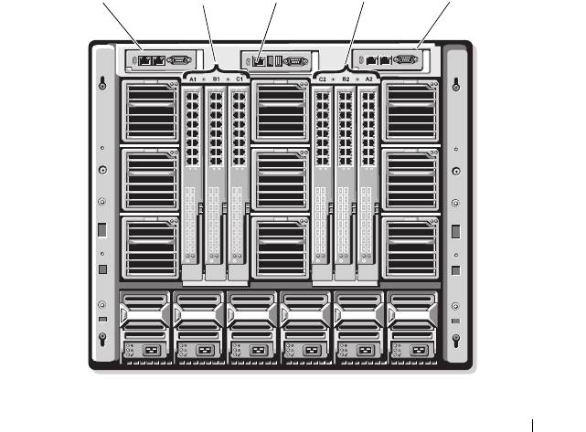
. Figure 3-1 shows the numbering of the I/O bays and other
back-panel features.
Figure 3-1. I/O Module Bay Numbering
Configuring the I/O Modules 47
CMC 1
A1 B1 C1
iKVM
C2 B2 A2
CMC 2
1
2
3
4
5
6
7
8
9
123456
book.book Page 47 Wednesday, March 9, 2011 3:11 PM

book.book Page 48 Wednesday, March 9, 2011 3:11 PM
Fabric A
Fabric A is a redundant Gb Ethernet fabric, supporting I/O module slots A1
and A2. The integrated Ethernet controllers in each blade dictate Fabric A as
an Ethernet-only fabric.
NOTE: Fabric A supports KR (10 Gbps standard) if the midplane version in the
enclosure is 1.1 or later. To identify the midplane version, see "Identifying Midplane
Version" on page 49.
NOTE: Modules designed specifically for Fabric B or Fabric C cannot be installed in
slots A1 or A2, as indicated by the color-coded label on the faceplate of each module.
Fabric B
Fabric B is a 1 to 40 Gb/sec redundant fabric, supporting I/O module slots B1
and B2. Fabric B currently supports 1 Gb or 10 Gb Ethernet, DDR/QDR
Infiniband, and 4 Gbps or 8 Gbps Fibre Channel modules. Additional fabric
types may be supported in the future.
NOTE: Fabric B supports up to 16 Gbps Fibre Channel, Infiniband FDR (14 Gbps
standard), and KR (10 Gbps standard) if the midplane version in the enclosure is 1.1
or later. To identify the midplane version, see "Identifying Midplane Version" on
page 49.
To communicate with an I/O module in the Fabric B slots, a blade must have
a matching mezzanine card installed in a Fabric B mezzanine card location.
Modules designed for Fabric A may also be installed in the Fabric B slots.
Fabric C
Fabric C is a 1 to 40 Gb/sec redundant fabric, supporting I/O module slots C1
and C2. Fabric C currently supports 1 Gb or 10 Gb Ethernet, DDR/QDR
Infiniband, and 4 Gbps or 8 Gbps Fibre Channel modules. Additional fabric
types may be supported in the future.
NOTE: Fabric C supports up to 16 Gbps Fibre Channel, Infiniband FDR (14 Gbps
standard), and KR (10 Gbps standard) if the midplane version in the enclosure is 1.1
or later. To identify the midplane version, see "Identifying Midplane Version" on
page 49.
To communicate with an I/O module in the Fabric C slots, a blade must have
a matching mezzanine card installed in a Fabric C mezzanine card location.
Modules designed for Fabric A may also be installed in the Fabric C slots.
48 Configuring the I/O Modules

book.book Page 49 Wednesday, March 9, 2011 3:11 PM
For more information about I/O module installation guidelines, see your
Hardware Owner’s Manual.
Identifying Midplane Version
The version of the midplane installed in the enclosure is displayed in the
Midplane Revision field under the Summary tab of the CMC web-based
interface.
You can also view the icons at the back of the enclosure to identify the version
of the midplane. See Table 3-1.
Table 3-1. Identifying Midplane Version
Marking Description Midplane Version
I/O module slots A1, A2 1.1
I/O module slots B1, B2, C1,
1.1
and C2
I/O module slots A1, A2 1.0
I/O module slots B1, B2, C1,
1.0
and C2
See Figure 3-2 and Figure 3-3 to locate the midplane identification labels on
the enclosure.
Configuring the I/O Modules 49
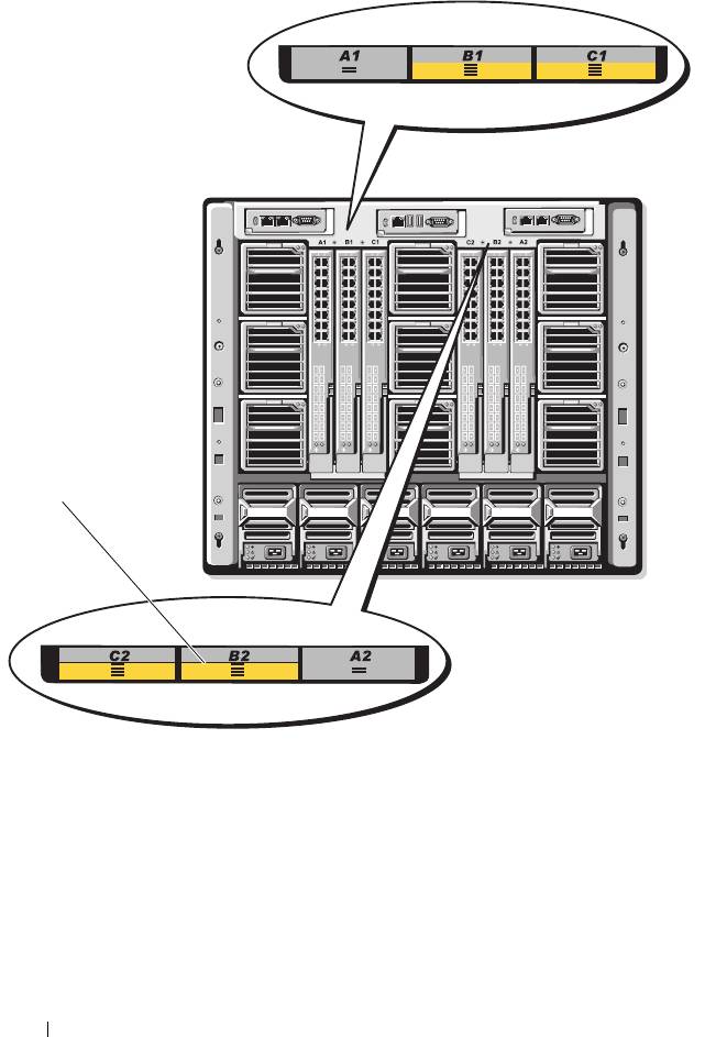
Figure 3-2. Identifying Midplane Version 1.1
1 midplane identification labels (2)
50 Configuring the I/O Modules
1
book.book Page 50 Wednesday, March 9, 2011 3:11 PM
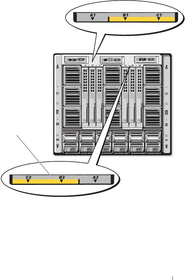
Figure 3-3. Identifying Midplane Version 1.0
1 midplane identification labels (2)
Configuring the I/O Modules 51
1
book.book Page 51 Wednesday, March 9, 2011 3:11 PM

book.book Page 52 Wednesday, March 9, 2011 3:11 PM
Before You Begin
Network Information
You can configure your I/O switch modules using:
• The CMC (see "Configuring a Switch Module Network Ethernet Port
Using the Web-Based Interface" on page 52).
NOTE: The default IP address for the CMC is 192.168.0.120.
• The CMC CLI using serial console redirection.
• Direct access to the I/O module’s serial port (if supported).
• The I/O module’s default IP address (if supported).
Switch Modules
Configuring a Switch Module Network Ethernet Port Using the
Web-Based Interface
You can use the CMC Web-based interface to configure an I/O module’s
Ethernet port.
NOTE: Use this procedure to configure the switch’s out-of-band Ethernet port. The
switch’s in-band management IP address is configured through the switch’s
external ports. These two IP addresses must be different, and on different
networks.
NOTE: To change settings on the I/O module configuration page, you must have
Fabric Administrator privileges for the particular Fabric in which the module is
installed.
NOTE: The network IP address set on the I/O module by the CMC is not saved to a
configuration file. To save the IP address configuration permanently, use the
connect switch-n RACADM command, or use a direct interface to the I/O
module GUI.
NOTE: Do not attempt to configure I/O module network settings for Ethernet pass-
through or Infiniband switches.
1
Log in to the CMC’s Web-based interface. See "Logging in to the CMC
Using the Web-Based Interface" on page 31.
2
Select
I/O Modules
in the
Chassis
menu in the system tree.
52 Configuring the I/O Modules

book.book Page 53 Wednesday, March 9, 2011 3:11 PM
3
Select the
Setup
tab. The
Configuring
I/O Modules Network Settings
page is displayed.
4
Configure the switch for integration into your network.
– Select
DHCP Mode Enabled
if your network uses a DHCP server to
assign IP addresses.
– If your network uses static IP addressing, enter an IP address, subnet
mask and gateway.
5
When you have finished, click
Apply
.
6
Click the
Deploy
sub-tab.
After all I/O modules have been configured and connected, the enclosure’s
blades can be inserted and booted with full network communication.
Dell PowerConnect-KR 8024-k Switch
The PowerConnect M8024-k switch provides 16 internal 10 GbE ports, four
external 10 GbE SFP+ ports, and one 10 GbE expansion slot for 10 GbE
external uplinks. The expansion slot on the front panel can support:
• A 10 Gb Ethernet module with four optical SFP+ connectors
• A 10 Gb Ethernet module with three copper CX4 uplinks
• A 10 Gb Ethernet module with two copper 10GBASE-T uplinks
This module is hot-swappable and may be installed in Fabric A, B, or C.
Configuring the I/O Modules 53
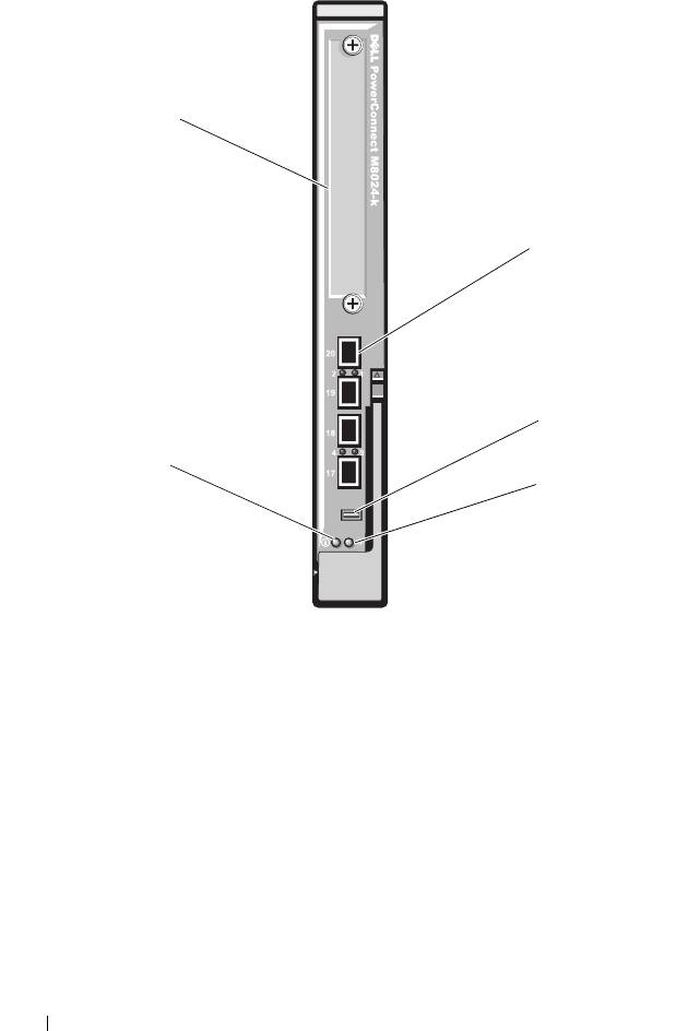
Figure 3-4. Dell PowerConnect-KR 8024-k Switch
1 SFP+ ports (4) 2 console management connector
3 status/identification indicator 4 power indicator
5 expansion slot
54 Configuring the I/O Modules
5
1
2
4
3
book.book Page 54 Wednesday, March 9, 2011 3:11 PM

book.book Page 55 Wednesday, March 9, 2011 3:11 PM
Dell M8428-k 10 Gb Converged Network Switch
The Dell M8428-k 10 Gb Converged Network switch module supports FCoE
protocols and allows Fibre Channel traffic to travel over 10 Gbps Enhanced
Ethernet (DCB) networks. This module consists of:
• Four 8 Gbps external autosensing Fibre Channel ports.
• Eight 10 Gb Enhanced Ethernet (DCB) optical SFP+ port connectors.
• Sixteen internal 10 Gb Enhanced Ethernet (DCB/FCoE) ports that link to
the blades in the enclosure.
• One serial port with an RJ-45 connector.
NOTE: This switch module includes Short Wave Small Form Factor Pluggable (SFP)
optical transceivers in the Fibre Channel ports. To ensure proper Fibre Channel
functionality, use only SFPs provided with this module.
This module can be installed in Fabric A, B, or C.
Configuring the I/O Modules 55
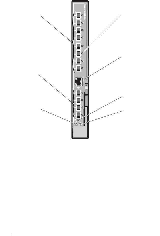
Figure 3-5. Dell M8428-k 10 Gb Converged Network Switch
1 LED status indicators (12) 2 serial port (RJ-45 connector)
3 module status indicator 4 status indicator
5 power indicator 6 8 Gb Fibre Channel ports
(ports 25–27 and port 0)
7 10 GbEE ports (ports 17–24)
56 Configuring the I/O Modules
1
7
2
6
3
5
4
book.book Page 56 Wednesday, March 9, 2011 3:11 PM
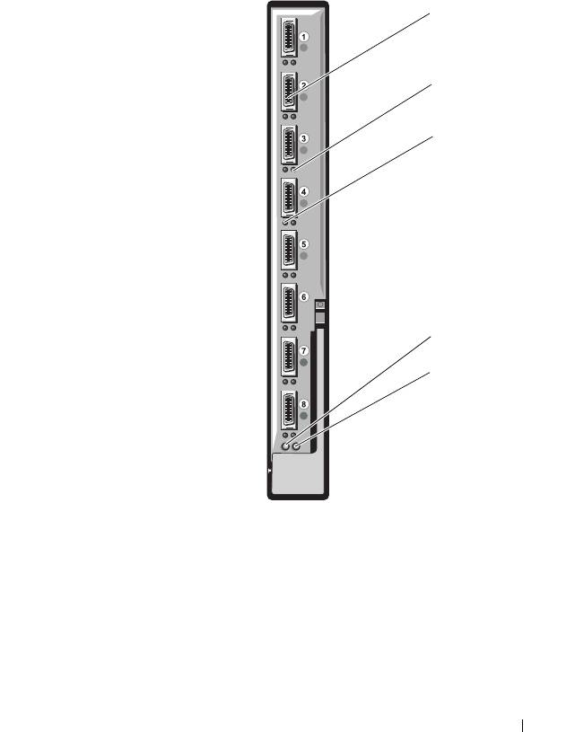
Mellanox M2401G DDR Infiniband Switch I/O Module
The Mellanox M2401G Infiniband switch I/O module includes 24 4x DDR
Infiniband ports. Eight ports are external uplink ports, while 16 internal ports
provide connectivity to the blades in the enclosure.
Figure 3-6. Mellanox M2401G Infiniband Switch Module
1 Infiniband ports (8) 2 port link status indicators (8)
3 port activity indicators (8) 4 module diagnostic power indicator
5 module status indicator
Configuring the I/O Modules 57
1
2
3
4
5
book.book Page 57 Wednesday, March 9, 2011 3:11 PM

book.book Page 58 Wednesday, March 9, 2011 3:11 PM
Mellanox M3601Q QDR Infiniband Switch I/O Module
The Mellanox M3601 Infiniband switch I/O module includes 32 4x QDR
Infiniband ports. Of these, 16 ports are external uplink ports, while 16
internal ports provide connectivity to the blades in the enclosure. This
module occupies two I/O module slots. By default, the M3610Q module
plugs into I/O module slot C1, but occupies both slots B1 and C1. It can also
be plugged into I/O module slot B1 (occupying slots A1 and B1) or slot B2
(occupying slots B2 and C2).
58 Configuring the I/O Modules
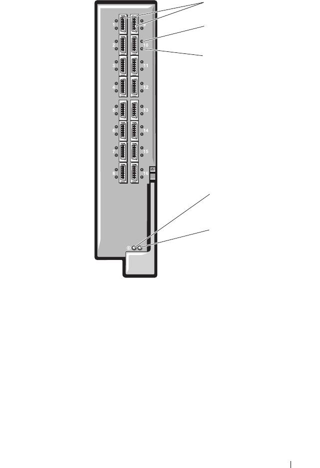
Figure 3-7. Mellanox M3601Q Infiniband Switch Module
1 Infiniband ports (16) 2 port link status indicators (16)
3 port activity indicators (16) 4 module diagnostic power indicator
5 module status indicator
Configuring the I/O Modules 59
1
2
3
4
5
book.book Page 59 Wednesday, March 9, 2011 3:11 PM
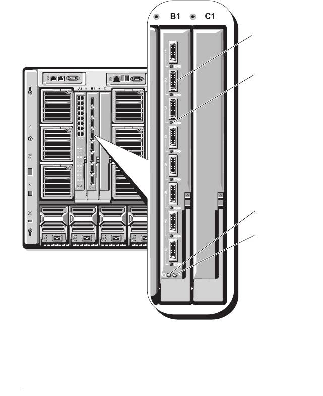
Cisco SFS M7000e Infiniband Switch I/O Module
The Cisco SFS M7000e Infiniband switch module includes 24 4x DDR
Infiniband ports. Eight ports are external uplink ports, and 16 internal ports
provide connectivity to the blades in the enclosure. This switch module is
hot-swappable, and may be installed in Fabric B or Fabric C.
Figure 3-8. Cisco SFS M7000e Infiniband Switch Module Features
1 Infiniband ports (8) 2 port status indicator (8)
3 diagnostic status indicator 4 power indicator
60 Configuring the I/O Modules
1
2
3
4
book.book Page 60 Wednesday, March 9, 2011 3:11 PM
