Dell POWEREDGE M1000E: instruction
Class: Household, kitchen appliances, electronics and equipment
Type:
Manual for Dell POWEREDGE M1000E
Table of contents
- Notes, Cautions, and Warnings
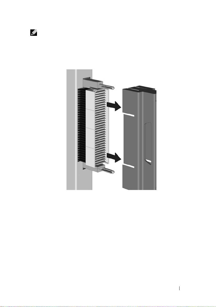
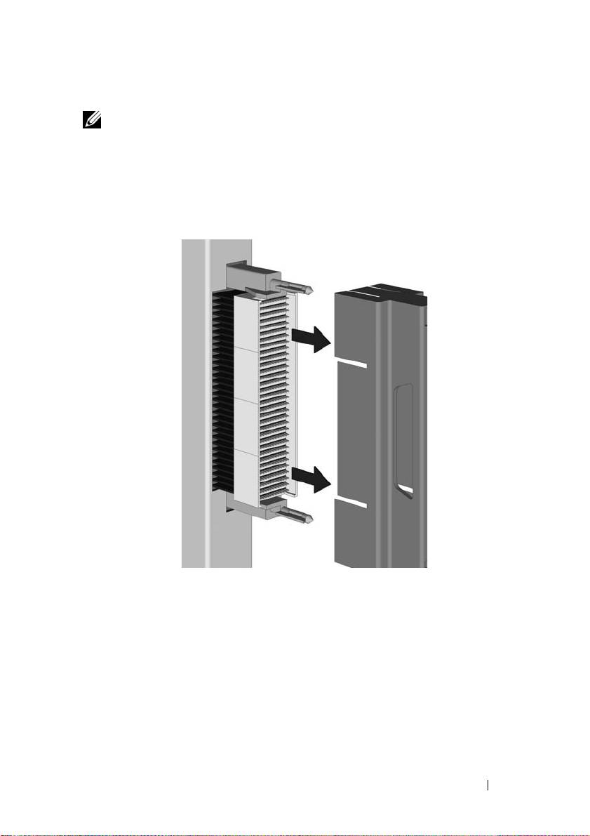
- 1. Install the Pass-Through Module Figure 1-1. Removing the Pin Cover
- Figure 1-2. Installing the Pass-Through Module 2. Attach a Fiber Optic Cable (Optional)
- 3. View Status LEDs Table 1-1. Port Status LED – Emulex Yellow LED Green LED State
- Table 1-1. Port Status LED – Emulex (continued) Yellow LED Green LED State Table 1-2. Port Status LED – QLogic Yellow LED Green LED State Table 1-3. Pass-Through Module Status LEDs Green LED Yellow/Blue LED State
- 4. Install Drivers 5. Having Problems? 6. Laser Safety

Dell FC8PT
Pass-Through Module
Quick Start Guide
Guía Rápido de Inicialización
Guide rapide de démarrage
Schnellanleitung
Guia de Início Rápido
빠른 시작 가이드
快速入门指南
快速入門指引
クイック スタート ガイド
Краткое руководство по установке
Instrukcja skrócona i instrukcja obsługi
Stručný návod
Οδηγός γρήγορης εκκίνησης
Panduan Cepat Memulai
Hızlı Başlangıç Kılavuzu
Regulatory Model: FC8PT
Regulatory Type: FC8PT


Dell FC8PT
Pass-Through Module
Quick Start Guide
Regulatory Model: FC8PT
Regulatory Type: FC8PT

Notes, Cautions, and Warnings
NOTE: A NOTE indicates important information that helps you make better use of
your computer.
CAUTION: A CAUTION indicates potential damage to hardware or loss of data if
instructions are not followed.
WARNING: A WARNING indicates a potential for property damage, personal
injury, or death.
____________________
Information in this publication is subject to change without notice.
© 2010-2011 Dell Inc. All rights reserved.
Reproduction of these materials in any manner whatsoever without the written permission of Dell Inc.
is strictly forbidden.
®
Trademarks used in this text: Dell™ and the DELL logo are trademarks of Dell Inc. Emulex
is a
®
registered trademark of Emulex. QLogic
is a registered trademark of QLogic Corporation.
Other trademarks and trade names may be used in this publication to refer to either the entities claiming
the marks and names or their products. Dell Inc. disclaims any proprietary interest in trademarks and trade
names other than its own.
Regulatory Model: FC8PT
Regulatory Type: FC8PT
March 2011 P/N VFNH3 Rev. A01
P006304-01A Rev. A
1. Install the Pass-Through Module
NOTE: Computer equipment contains static-sensitive components that may be
damaged during handling. Static precautions such as grounded wrist straps are
recommended during the installation process.
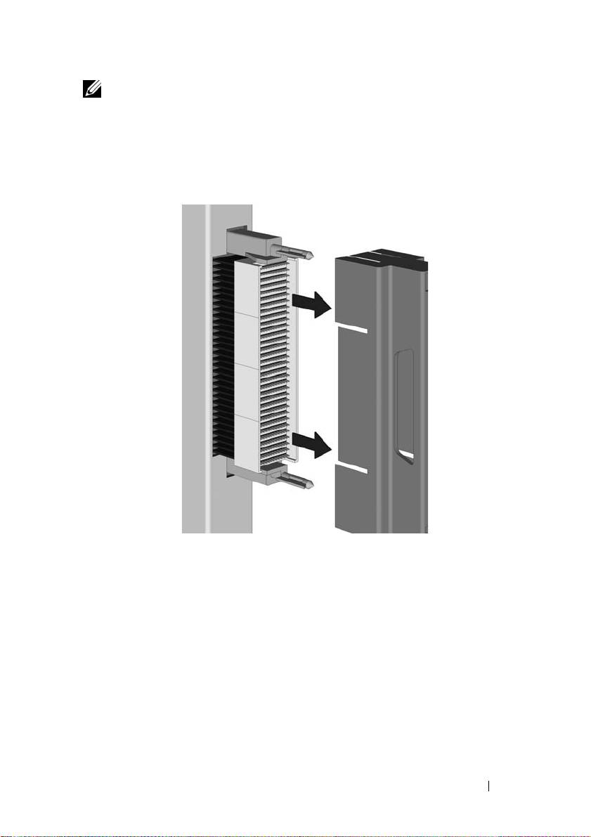
1
Remove the pin cover from the connector pins at the back of the pass-
through module, as shown in Figure 1-1, Removing the Pin Cover.
Figure 1-1. Removing the Pin Cover
2
Locate an empty module bay in the server.
3
If the selected bay contains an I/O module blank, remove it.
4
Make sure that the latching arm is in the unlatched position, and slide the
pass-through module into the bay until it stops.
FC8PT Pass-Through Module 5

Figure 1-2. Installing the Pass-Through Module
5
Rotate the latching arm upward until it is flush against the front panel,
and the top of the arm is seated in the latch, as shown in Figure 1-2,
Installing the Pass-Through Module.
2. Attach a Fiber Optic Cable
(Optional)
Install a fiber optic cable between the pass-through module and the target
device. With short-wave lasers, use multimode fiber optic cable that adheres
to the following specifications.
Fiber Optic Cable Maximum Length Minimum
Connector
Length
62.5/125 μm (multimode) 200
150 meters at 2.125 Gb/s
.5 meters LC
MHz*km bandwidth cable
70 meters at 4.25 Gb/s
21 meters at 8.5 Gb/s
6 FC8PT Pass-Through Module
Fiber Optic Cable Maximum Length Minimum
Connector
Length
50/125 μm (multimode) 500
300 meters at 2.125 Gb/s
.5 meters LC
MHz*km bandwidth cable
150 meters at 4.25 Gb/s
50 meters at 8.5 Gb/S
1
Connect the fiber optic cables to the LC connectors on the pass-through
module.
2
Connect the other end of the cable to the target Fibre Channel device.
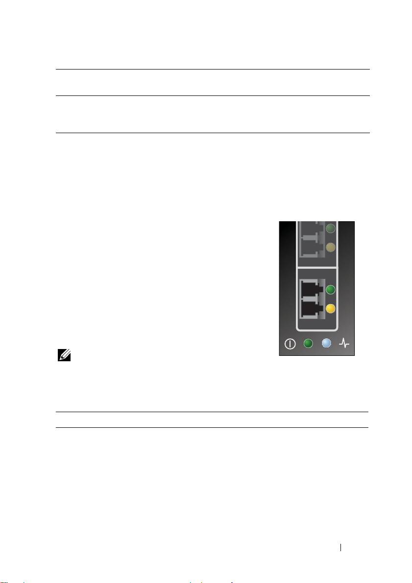
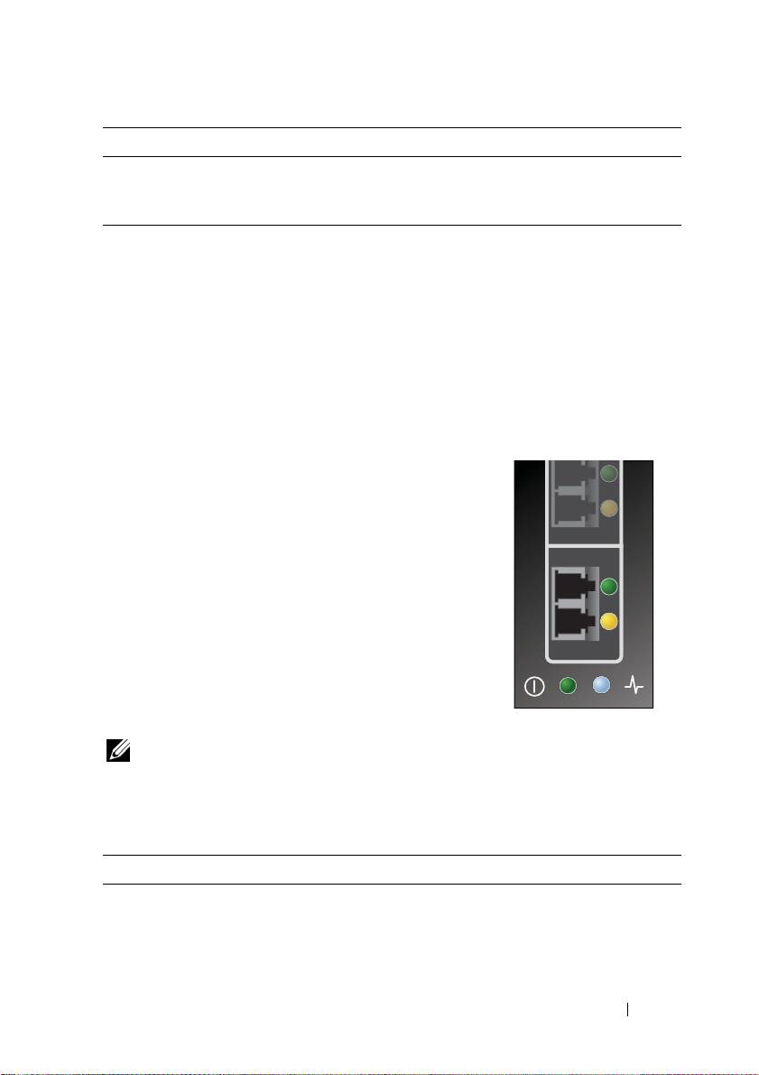
3. View Status LEDs
The pass-through module contains several light-
emitting diodes (LEDs). Each port includes a pair of
LEDs (one green and one yellow) that indicate the
status of the ports on the SFP. Power-on self test
(POST) conditions and results are summarized in
Tables 1-1 and 1-2. In addition, at the bottom of the
pass-through module faceplate is an additional pair
of LEDs (one blue and one green) that provide the
status of the pass-through module. Pass-through
module status LEDs are shown in Table 1-3, Pass-
Through Module Status LEDs.
NOTE: For the link rate conditions, there is a one
second pause when the LED is off between each
group of fast blinks (2, 3, or 4). You should observe the LED sequence for several
seconds to ensure that the pause is correctly identified.
Table 1-1. Port Status LED – Emulex
Yellow LED Green LED State
Off Off Wake-up failure (dead board)
On Off POST failure (dead board)
Slow blink Off Wake-up failure monitor
Fast blink Off POST failure
Flashing Off POST processing in progress
Off On Failure while functioning
FC8PT Pass-Through Module 7

Table 1-1. Port Status LED – Emulex (continued)
Yellow LED Green LED State
On On Failure while functioning
2 fast blinks On 2-Gb link rate – normal link up
3 fast blinks On 4-Gb link rate – normal link up
4 fast blinks On 8-Gb link rate – normal link up
Off Slow blink Normal link down or not started
Slow blink Slow blink Off-line for download
Fast blink Slow blink Restricted off-line mode (waiting for restart)
Flashing Slow blink Restricted off-line mode (test active)
Table 1-2. Port Status LED – QLogic
Yellow LED Green LED State
Off Off Power off
On On Power on (before firmware initialization)
Flash Flash Firmware fault
Off On Link up
Off Flash Activity
Flash Off Beacon
Table 1-3. Pass-Through Module Status LEDs
Green LED Yellow/Blue LED State
Off Off The pass-through module is powered off or
an error condition exists
On On (blue) The pass-through module is healthy
On Blinking (yellow) Pass-through module fault
On Off Booting up
On Blinking (blue) Chassis Management Controller identifies
pass-through module
8 FC8PT Pass-Through Module

4. Install Drivers
There are no drivers, firmware, or boot code for this device. Utility software, if
applicable, is located in the Technical Support section of the Dell website
(www.dell.com).
5. Having Problems?
Notwithstanding language to the contrary in any other Dell documentation
or on any Dell website, the limited warranty applicable to Dell branded
products described in the Product Information Guide and/or on the local
country Dell website shall apply to the FC8PT Pass-Through Module.
6. Laser Safety
Install only CDRH Certified Class 1 Laser Devices.
FC8PT Pass-Through Module 9

Dell FC8PT
Pass-Through Module
Guía Rápido de Inicialización
Model de reglamentación: FC8PT
Tipo de reglamentación: FC8PT

Notas, precauciones y advertencias
NOTA: Las NOTAS presentan información importante que le ayuda a utilizar
mejor su PC.
PRECAUCIÓN: Las PRECAUCIONES muestran el potencial daño al hardware
o la potencial pérdida de datos si no se siguen las instrucciones.
ADVERTENCIA: Las ADVERTENCIAS indican un potencial daño a la propiedad,
daño personal o muerte.
____________________
La información de esta publicación puede ser modificada sin previo aviso.
© 2010-2011 Dell Inc. Todos los derechos reservados.
Queda prohibida la reproducción de cualquier parte de este material sin el consentimiento escrito
de Dell Inc.
Marcas registradas utilizadas en este texto: Dell™ y el logo de DELL son marcas registradas de Dell
®
®
Inc. Emulex
es marca registrada de Emulex. QLogic
es marca registrada de QLogic Corporation.
Es posible que se utilicen otras marcas y nombres registrados en esta publicación para hacer referencia
a entidades que tienen derechos sobre las marcas y los nombres de sus productos. Dell Inc. desconoce
derechos de propiedad sobre marcas registradas y nombres comerciales que no sean los propios.
Model de reglamentación: FC8PT
Tipo de reglamentación: FC8PT
Marzo de 2011 P/N VFNH3 Rev. A01
P006304-01A Rev. A
1. Instalación del módulo
de transferencia
NOTA: La computadora contiene componentes sensibles a la estática que se
pueden averiar durante su manipulación. Se recomienda adoptar precauciones
contra estática, como muñequeras con tierra durante el proceso de instalación.
1
Retire la cubierta de la clavija del conector de clavijas en la parte trasera
del módulo de transferencia, como se muestra en la Figura 1-1, Remoción
de la cubierta de la clavija.
Figura 1-1. Remoción de la cubierta de la clavija
2
Ubique el módulo vacío en el servidor.
3
Si el compartimiento seleccionado contiene un módulo E/s en blanco, retírelo.
4
Asegúrese de que el brazo de enganche se encuentre desenganchado y deslice
el módulo de transferencia en el compartimiento hasta que llegue al tope.
Módulo de transferencia FC8PT 12
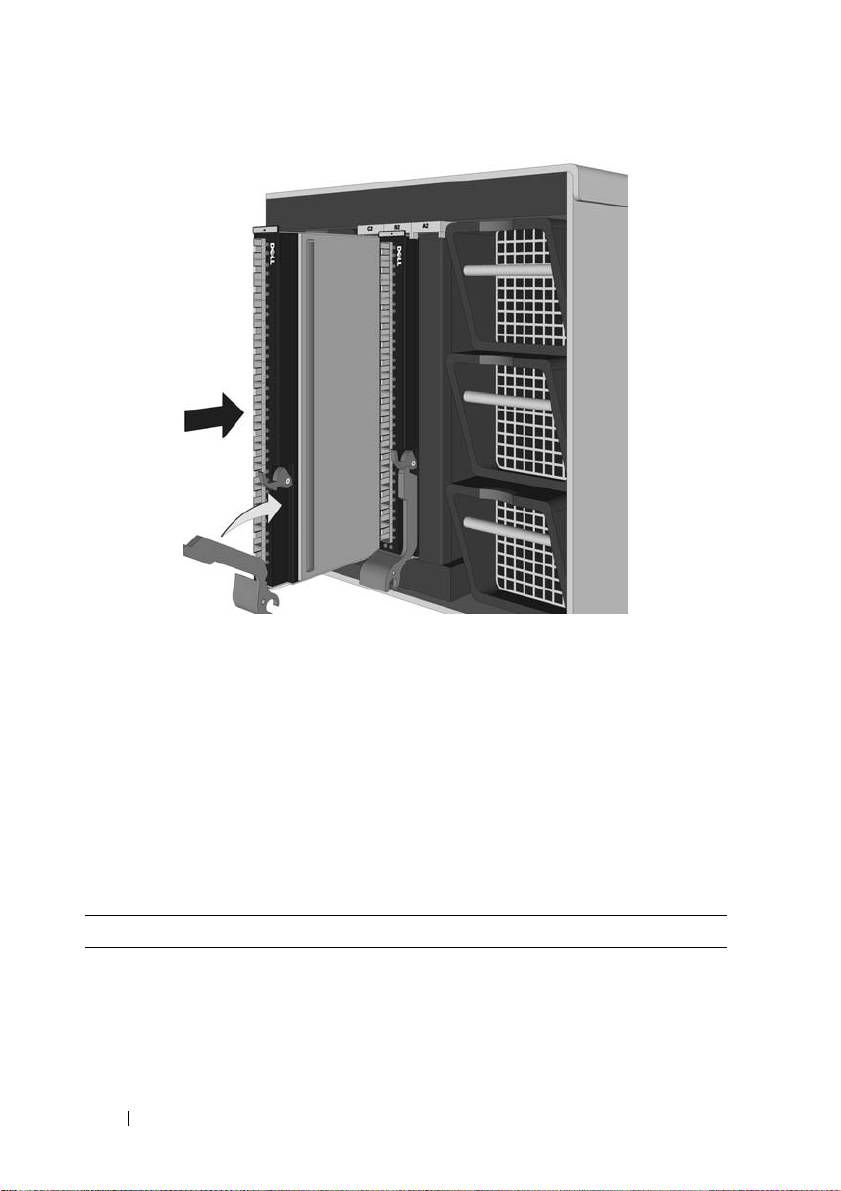
Figura 1-2. Instalación del módulo de transferencia
5
Rote el brazo de enganche hacia arriba hasta que quede nivelado con el
panel frontal y la parte superior del brazo se apoye sobre el enganche como
se muestra en la Figura 1-2, Instalación del módulo de transferencia.
2. Conecte el Cable de fibra óptica
(opcional)
Instale un cable de fibra óptica entre el módulo de transferencia
y el dispositivo de destino. Con láser de onda corta, utilice cable de fibra
óptica de modo múltiple que cumpla las siguientes especificaciones.
Cable de fibra óptica Largo máximo Largo mínimo Conector
Cable de ancho de banda de
150 metros a 2,125 Gb/seg.
0,5 metros LC
62,5/125 μm (modo múltiple)
70 metros a 4,25 Gb/seg.
200 MHz*km
21 metros a 8,5 Gb/seg.
13 Módulo de transferencia FC8PT
Cable de fibra óptica Largo máximo Largo mínimo Conector
Cable de ancho de banda de
300 metros a 2,125 Gb/seg.
0,5 metros LC
50/125 μm (modo múltiple)
150 metros a 4,25 Gb/seg.
500 MHz*km
50 metros a 8,5 Gb/seg.
1
Conecte los cables de fibra óptica a los conectores LC en el módulo de
transferencia.
2
Conecte el otro extremo del cable en el dispositivo de canal de fibra
de destino.
3. Ver los diodos emisores de luz
de estados (LED)
El módulo de transferencia contiene una gran cantidad
de diodos emisores de luz (LED).
Cada punto de falla contiene un par de LED
(uno de color verde y otro amarillo) que indican el
estado de los puertos en el punto de falla. Las
condiciones y los resultados del autotest (POST)
de Power-on están resumidas en las tablas 1-1 y 1-2.
Además, en la parte inferior de la placa frontal del
módulo de transferencia hay un par de LED (uno
de color azul y otro verde) que indican el estado del
módulo de transferencia. Los LED que indican el
estado del módulo de transferencia se muestran en
Tabla 1-3, LED de estado del módulo de transferencia.
NOTA: Para las condiciones de la tasa de conexión existe una pausa de un
segundo cuando el LED está apagado entre cada grupo de pestañeos rápidos
(2, 3 ó 4). Debe observarse la secuencia del LED durante varios segundos para
asegurarse que la pausa está identificada correctamente.
Tabla 1-1. LED del estado del puerto – Emulex
LED amarillo LED verde Estado
Apagado Apagado Falla de activación (placa muerta)
Prendido Apagado Falla del POST (placa muerta)
Pestañeo lento Apagado Monitor de falla de activación
Módulo de transferencia FC8PT 14

Tabla 1-1. LED del estado del puerto – Emulex (Cont.)
LED amarillo LED verde Estado
Pestañeo rápido Apagado Falla del POST
Pestañeando Apagado Procesamiento del POST en operación
Apagado Prendido Falla de funcionamiento
Prendido Prendido Falla de funcionamiento
2 pestañeos rápidos Prendido Tasa de conexión de 2 Gb – conexión normal
3 pestañeos rápidos Prendido Tasa de conexión de 4 Gb – conexión normal
4 pestañeos rápidos Prendido Tasa de conexión de 8 Gb – conexión normal
Apagado Pestañeo lento Desconexión normal o no iniciado
Pestañeo lento Pestañeo lento Off-line para download
Pestañeo rápido Pestañeo lento Modo off-line restricto (aguardando
para reiniciar)
Pestañeando Pestañeo lento Modo off-line restricto (test activo)
Tabla 1-2. LED del estado del puerto – QLogic
LED amarillo LED verde Estado
Apagado Apagado Apagado
Prendido Prendido Encendido (antes de la inicialización del
firmware)
Pestañeo Pestañeo Fallas en el firmware
Apagado Prendido Enlace activo
Apagado Pestañeo Actividad
Pestañeo Apagado Baliza
Tabla 1-3. LED del módulo de transferencia
LED verde LED amarillo/azul Estado
Apagado Apagado El módulo de transferencia está apagado o
hay un error
Prendido Prendido (azul) El interruptor funciona
15 Módulo de transferencia FC8PT

Tabla 1-3. LED del módulo de transferencia (Cont.)
LED verde LED amarillo/azul Estado
Prendido Pestañeo (amarillo) El interruptor tiene fallas
Prendido Apagado Arranque
Prendido Pestañeo (azul) El controlador de gestión de bastidor
identifica el módulo de transferencia
4. Instalación de los drivers
No existen drivers, firmware ni código de inicio para este dispositivo.
El software de la utilidad, si corresponde, se encontrará en la sección de
Soporte en el sitio web de Dell (www.dell.com).
5. ¿Tiene Problemas?
A no ser cuando se especifique de otra forma en otros documentos de Dell o
en cualquier sitio de Dell, en cualquier idioma, la garantía de los productos
marca Dell en la Guía de informaciones del producto y/o en el sitio local de
Dell se aplicará al módulo de transferencia FC8PT.
6. Seguridad del láser
Instale únicamente dispositivos de láser Clase 1 aprobados por el Centro para
Dispositivos y Salud Radiológica (CDRH).
Módulo de transferencia FC8PT 16

Dell FC8PT
Pass-Through Module
Guide rapide de démarrage
Modèle Réglementaire : FC8PT
Type Réglementaire : FC8PT

Remarques, mises en garde et avertissements
REMARQUE : Une REMARQUE indique des informations importantes qui vous
aident à mieux utiliser votre ordinateur.
MISE EN GARDE : Une MISE EN GARDE indique des dommages potentiels au
matériel ou la perte de données si les instructions ne sont pas suivies.
AVERTISSEMENT : Un AVERTISSEMENT indique un risque de dommages
matériels, dommages corporels ou de décés.
____________________
Les informations contenues dans ce document sont sujettes à modification sans préavis.
© 2010-2011 Dell Inc. Tous droits réservés.
La reproduction de ces documents de quelque manière que ce soit sans l’autorisation écrite de
Dell Inc. est strictement interdite.
Marques commerciales utilisées dans ce texte : Dell™ et le logo DELL sont des marques de commerce
®
®
de Dell Inc. Emulex
est une marque déposée d’Emulex. QLogic
est une marque déposée de QLogic
Corporation.
D’autres marques et noms commerciaux peuvent être utilisés dans ce document pour faire référence
aux entités revendiquant les marques et noms ou leurs produits. Dell dénie tout intérêt propriétaire
aux marques et noms commerciaux autres que les siens.
Modèle Réglementaire : FC8PT
Type Réglementaire : FC8PT
Mars 2011 P/N VFNH3 Rév. A01
P006304-01A Rév. A
1. Installez le module de passerelle
REMARQUE : Les équipements informatiques contiennent des composants
sensibles à l’électricité statique pouvant être endommagés pendant leur
manipulation. Prendre des précautions, par exemple en portant un bracelet
antistatique, est donc conseillé lors de l’installation.
1
Retirez le cache des broches de connexion à l’arrière du module de
passerelle, comme illustré à la Figure 1-1, Retrait du cache des broches
Figure 1-1. Retrait du cache des broches
2
Localisez une baie de module vide dans le serveur.
3
Si la baie sélectionnée contient un panneau de remplissage pour module
E/S, retirez-le.
4
Assurez-vous que le bras de verrouillage se trouve en position déverrouillée et
faites coulisser le module de passerelle dans la baie jusqu’à ce qu’il s’arrête.
Module de passerelle FC8PT 19

Figure 1-2. Installation du module de passerelle
5
Pivotez le bras de verrouillage vers le haut jusqu’à ce qu’il soit aligné sur le
panneau avant, et que le sommet du bras soit logé dans le verrou, comme
illustré à la Figure 1-2, Installation du module de passerelle.
2. Fixez un câble à fibre optique
(facultatif)
Installez un câble à fibre optique entre le module de passerelle et le dispositif
cible. Avec des lasers à ondes courtes, utilisez un câble à fibre optique
multimode conforme aux spécifications suivantes.
Câble à fibre optique Longueur maximum Longueur
Connecteur
minimum
62,5/125 μm (multimode)
150 mètres à 2,125 Gb/s
0,5 mètre LC
200 MHz*km câble à
70 mètres à 4,25 Gb/s
bande passante
21 mètres à 8,5 Gb/s
20 Module de passerelle FC8PT
