Dell J730N: instruction
Class: Tools, power tools and power equipment
Type:
Manual for Dell J730N
Table of contents
- Getting Started With Your System
- Notes and Warnings
- System Features
- Finding Information
- Installation and Startup Unpacking the System
- Lifting the Cabinet
- Identifying the UPS Figure 1. The Dell Online Rack UPS Front Panel Figure 2. 3750W, 208V Rear Panel
- Figure 3. 3750W, 230V Rear Panel Figure 4. 4200W, 208V Rear Panel
- Figure 5. 4200W, 230V Rear Panel
- Rackmount Setup Removing the Battery Retaining Bracket
- Removing the Battery Trays
- Installing the Rails
- Installing the Cabinet
- Securing the Cabinet Installing the Battery Tray
- Replacing the Battery Retaining Bracket and Connecting the Internal Battery Connectors
- Installing the UPS Front Cover Connecting the Equipment
- Connecting the Power Cord (3750W/208V Models Only)
- Hardwiring the UPS Input Figure 6. Circuit Breaker Diagram
- Removing the Terminal Block Cover
- Installing the Input and Ground Wires
- Starting the UPS
- Completing the Startup

Dellt Online Rack UPS
3750W and 4200W
Getting Started With
Your System
Démarrarer avec Votre Système
Erste Schritte Mit Ihrem System
Начало работы c вашей системой
Inicio de su sistema
系统使用 入门指南
系統使用 入門指南
사용자의 시스템 시작하기
はじめに システムについて
K804N, H952N, J730N, K805N
J739N
www.dell.com | support.dell.com


Dellt Online Rack UPS
3750W and 4200W
Getting Started
With Your System
K804N, H952N, J730N, K805N
J739N
www.dell.com | support.dell.com

Notes and Warnings
NOTE: A NOTE indicates important information that helps you make better use of your software.
DANGER: A DANGER indicates an imminently hazardous situation which, if not avoided, will result in death or
serious injury.
WARNING: A WARNING indicates a potentially hazardous situation which, if not avoided, could result in death or
injury.
CAUTION: A CAUTION indicates a potentially hazardous situation which, if not avoided, may result in minor or
moderate injury or in property damage incidents.
DANGER: Observe the following instruction to help prevent an imminently hazardous situation which, if not
avoided, will result in death or serious injury:
S This UPS contains LETHAL VOLTAGES. All repairs and service should be performed by
AUTHORIZED SERVICE PERSONNEL ONLY.ThereareNO USER SERVICEABLE PARTS
inside the UPS.
Information in this document is subject to change without notice.
E 2009 Dell Inc. All rights reserved.
Reproduction in any manner whatsoever without the written permission of Dell Inc. is strictly forbidden.
Trademarks used in this text: Dell and the DELL logo are trademarks of Dell Inc.
Other trademarks and trade names may b e used in this document to refer to either the entities claiming the marks and names or their
products. Dell Inc. disclaims any proprietary interest in trademarks and trade names other than its own.
July 2009

System Features
Providing outstanding performance and reliability, the UPS's unique benefits i nclude:
S Online UPS design with pure sine wave output. The UPS filters and regulates incoming AC power
and provides consistent power to your equipment without draining the battery.
S True online double-conversion technology with high power density, utility frequency
independence, and generator compatibility.
S Selectable High Efficiency mode of operation.
S 4U size that fits any standard 48 cm (19”) rack.
S Start-on-battery capability for powering up the UPS even if utility power is not available.
S Extended runtime with an optional Extended Battery Module (EBM).
S Emergency shutdown control through the Remote Emergency Power-off (REPO) ports.
S Two standard communication ports (USB and DB-9 serial port).
S Optional Dell Network Management Card with enhanced communication capabilities for
increased power protection and control.
S Advanced power management with the Dell UPS Management Software for graceful shutdowns
and power monitoring.
S Sequential shutdown and load management through separate receptacle groups called l oad
segments.
S Firmware that is easily upgradable without a service call.
S Backed by worldwide agency approvals.
System Features
|
3
Finding Information
CAUTION: The Safety, Environmental, and Regulatory Information document provides important safety and
regulatory information.
What are You Looking For?
Find It Here
S The user's guide for my UPS
Dell UPS Disc
S The user's guide for the Dell Network Management
Card
S Dell UPS Management Software
NOTE: Documentation and software updates can be
found at
support.dell.com.
S Specifications
Dell UPS User's Guide
S How to configure UPS settings
The user's guide is available on the Dell UPS disc and
S How to troubleshoot and solve problems
on support.dell.com.
S How to install REPO control
S Safety instructions
Safety, Environmental, and Regulatory Information
S Regulatory information
S Recycling information
S Warranty information
Dell Warranty and Support Information
S Terms and Conditions (U.S. only)
S End User License Agreement
S Support information Dell Support Website — support.dell.com
NOTE: Select your region or business segment to view
the appropriate support site.
4
|
Finding Information
Installation and Startup
CAUTION: Before performing the procedures in this document, read and follow the safety instructions and
important regulatory information in your Safety, Environmental, and Regulatory Information document.
This section describes the steps to set up your system for the first time.
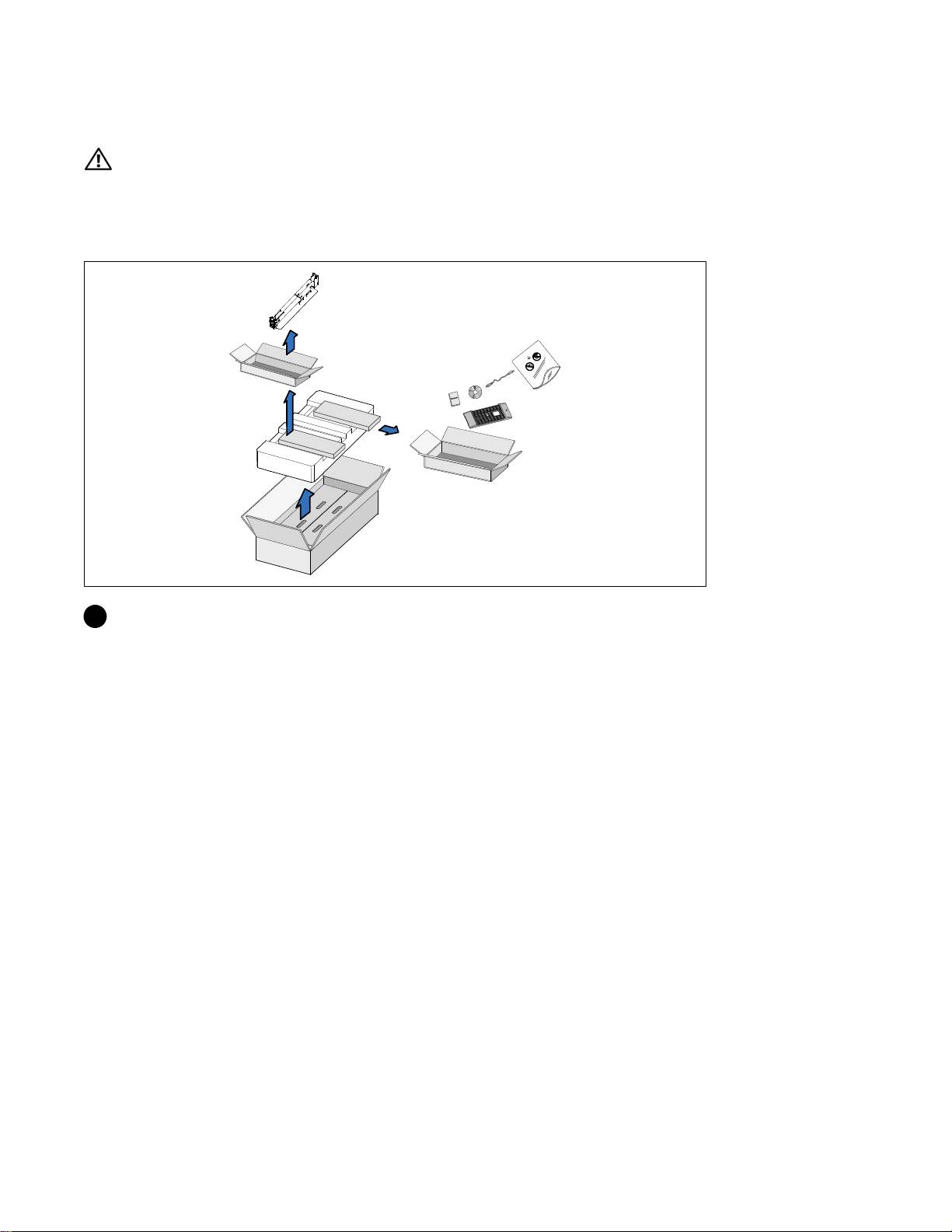
Unpacking the System
1 Open the outer carton and remove the accessories packaged with the cabinet.
Installation and Startup
|
5
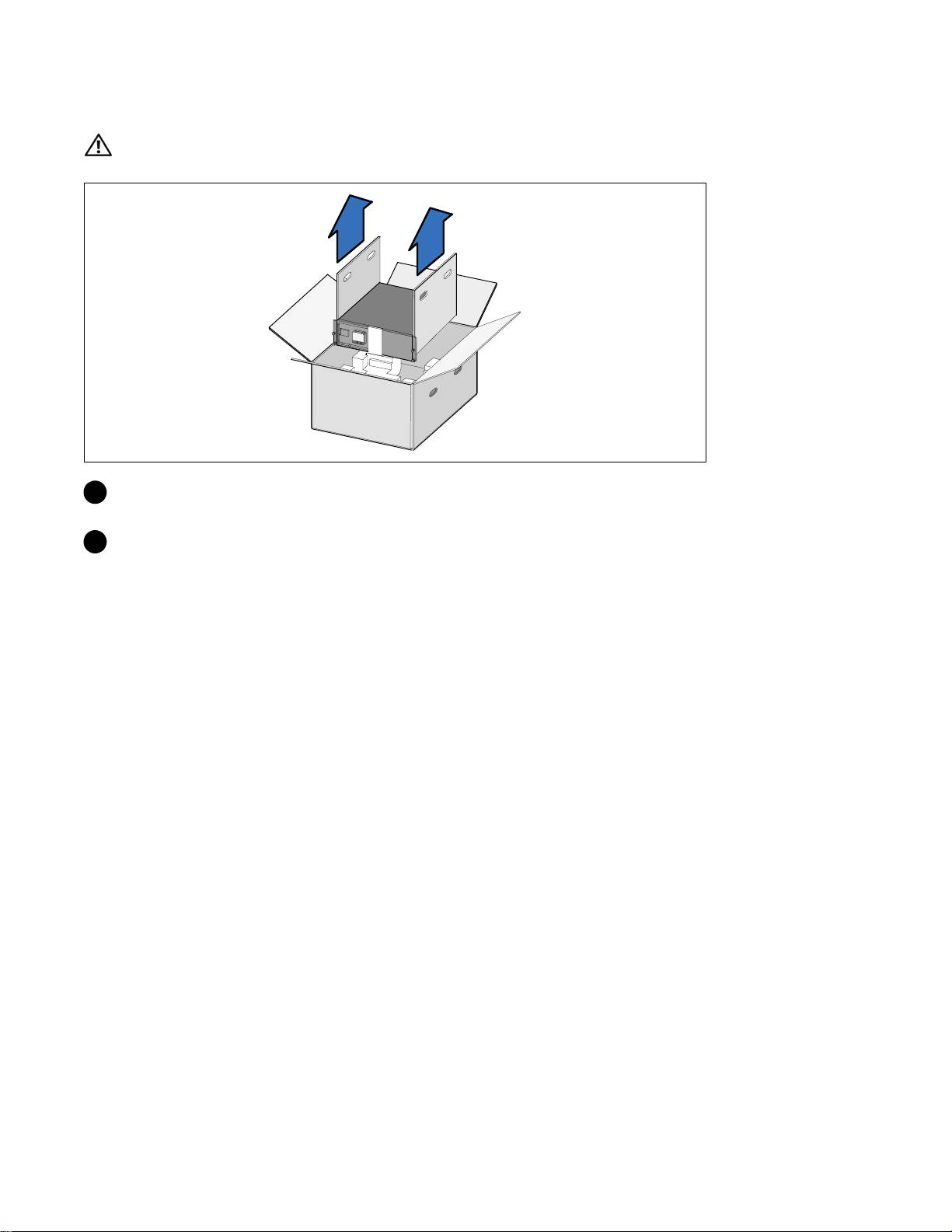
Lifting the Cabinet
CAUTION: The cabinet is heavy (66 kg/145.5 lb). Lifting the cabinets into the rack requires a minimum of two
people.
1 Withonepersononeachside,carefullyliftthecabinet out of the outer carton using the handles
on the cardboard and set it on a flat, stable surface.
2 Discard or recycle the packaging in a responsible manner, or store it for future use.
6
|
Installation and Startup
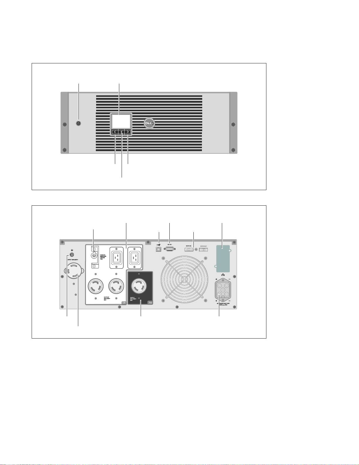
Identifying the UPS
This section shows a front and rear panel of the Dell Online Rack UPS.
On/Off Button
LCD Panel
Scroll Button (Up or Back)
Scroll Button (Down or Forward)
Select Button
Figure 1. The Dell Online Rack UPS Front Panel
Two IEC 320-C19 and Two L6-20 Receptacles
UPS
(Load Segment 2)
RS-232 Port
Communication Bay
USB Port
REPO Ports
Output Circuit Breaker
Ground Screw
One L6-30 Receptacle
EBM Connector
(Load Segment 1)
2m, L6-30P Power Cord
Figure 2. 3750W, 208V Rear Panel
Installation and Startup
|
7
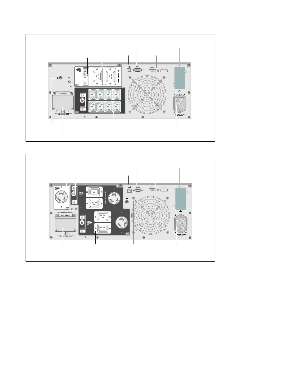
Two IEC 320-C19 Receptacles
UPS
(Load Segment 2)
RS-232 Port
Communication Bay
USB Port
REPO Ports
Output Circuit Breaker
Ground Screw
Eight IEC 320-C13 Receptacles
EBM Connector
(Load Segment 1)
Input Terminal Block
Figure 3. 3750W, 230V Rear Panel
One L6-30 Receptacles
UPS
(Load Segment 2)
RS-232 Port
Communication Bay
USB Port
REPO Ports
Output Circuit Breaker
Four IEC 320-C19 and
Ground Screw
EBM Connector
Input Terminal Block
Two L6-20 Receptacles
(Load Segment 1)
Figure 4. 4200W, 208V Rear Panel
8
|
Installation and Startup
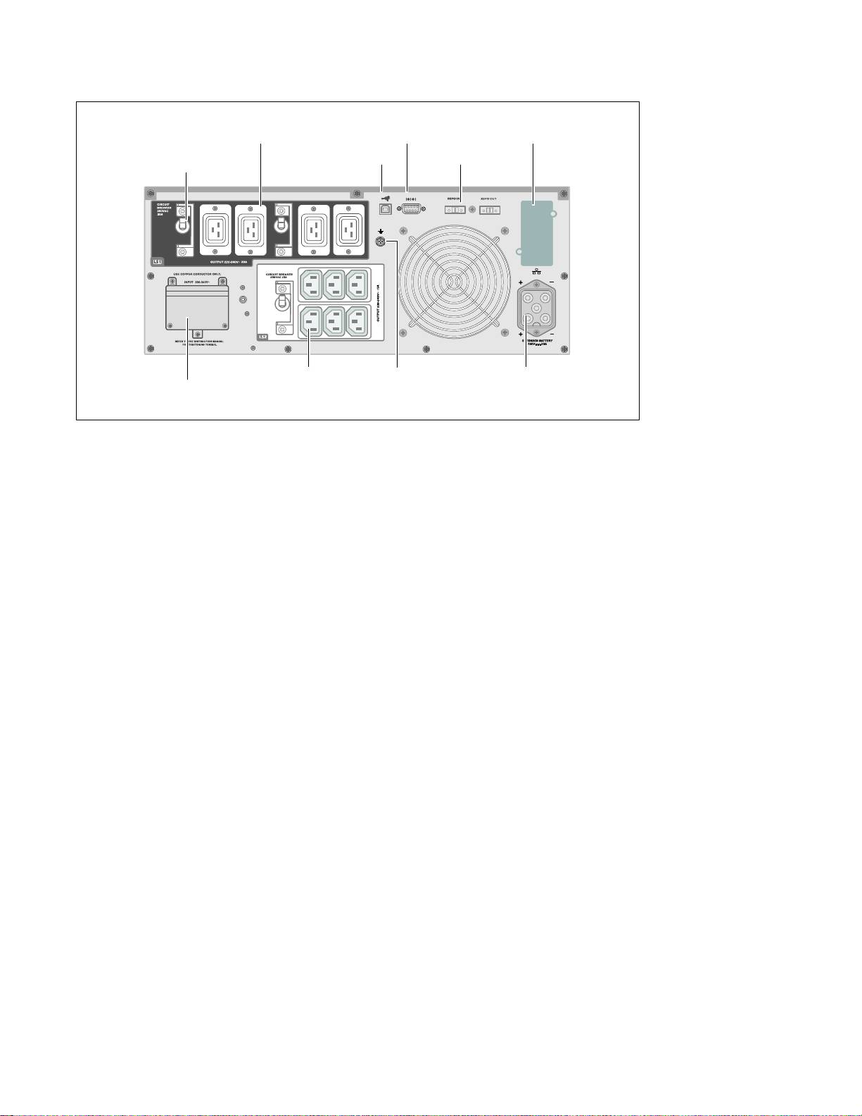
Four IEC 320-C19 Receptacles
UPS
(Load Segment 1)
RS-232 Port
Communication Bay
USB Port
REPO Ports
Output Circuit Breaker
Six IEC 320-C13 Receptacles
Ground Screw
EBM Connector
Input Terminal Block
(Load Segment 2)
Figure 5. 4200W, 230V Rear Panel
Installation and Startup
|
9
Rackmount Setup
CAUTION: The cabinet is heavy (66 kg/145.5 lb): 1) Dell strongly recommends to remove the battery tray from
the UPS before lifting. 2) Lifting the cabinets into the rack requires a minimum of two people.
CAUTION: Removing the batteries should be performed or supervised by personnel knowledgeable about
batteries and the required precautions. Keep unauthorized personnel away from batteries.
Removing the Battery Retaining Bracket
1 Loosen the thumbscrew on the battery retaining bracket and remove.
10
|
Installation and Startup
Removing the Battery Trays
2 Pull the battery trays using the plastic tabs and remove the battery trays.
Installation and Startup
|
11
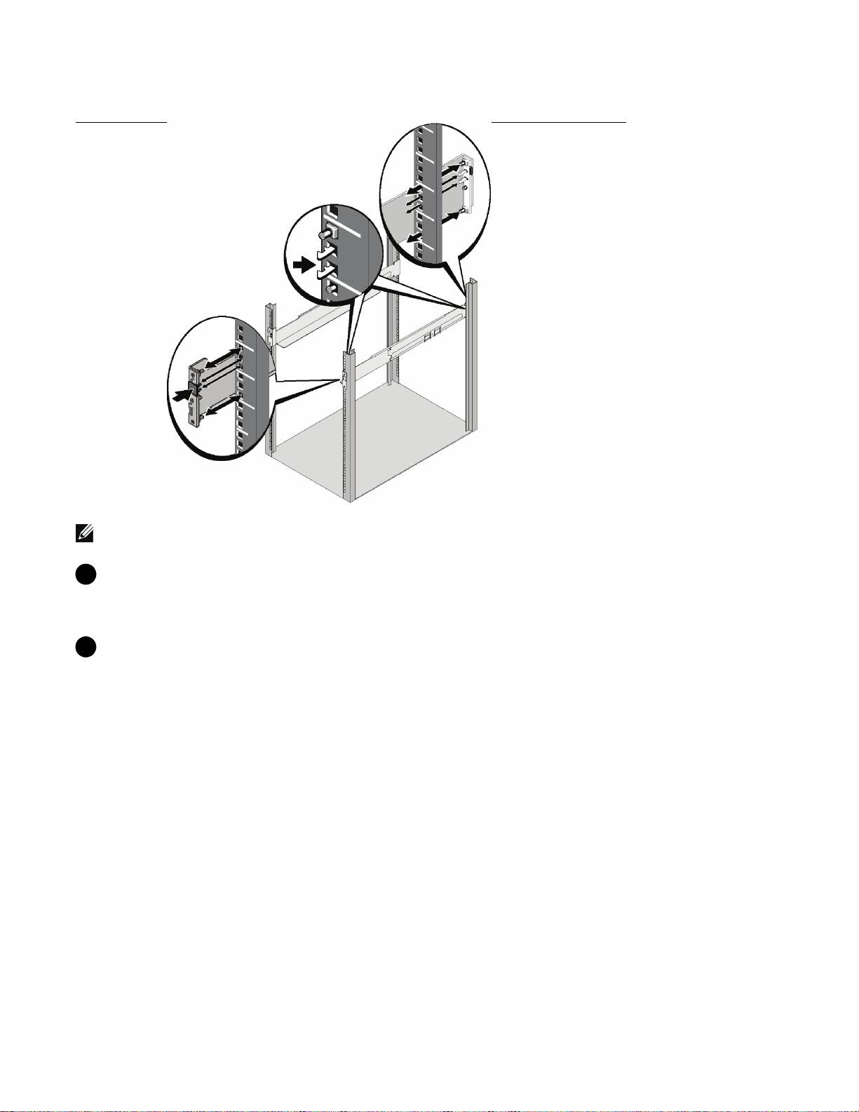
Installing the Rails
NOTE: The instructions are the same for square-hole racks and unthreaded, round-hole racks. The rails fit both
rack styles. The square-hole rack is shown in the illustrations.
3 Select the proper holes in the rail for positioningtheUPSinthedesiredlocationintherack.
The rails should be located at the bottom of the 4U space allocated for the UPS or 3U for the
EBM.
4 Position the end of the left and right rails labeled FRONT facing inward.
12
|
Installation and Startup
5 Attach the rails to the rack:
Engage the back end of the rail until it fully seats on the vertical rack flange and the hook latch
locks in place.
Pull the rail toward the front.
Push the front end of the rail until it fully seats on the vertical rack flange and the hook latch locks
in place.
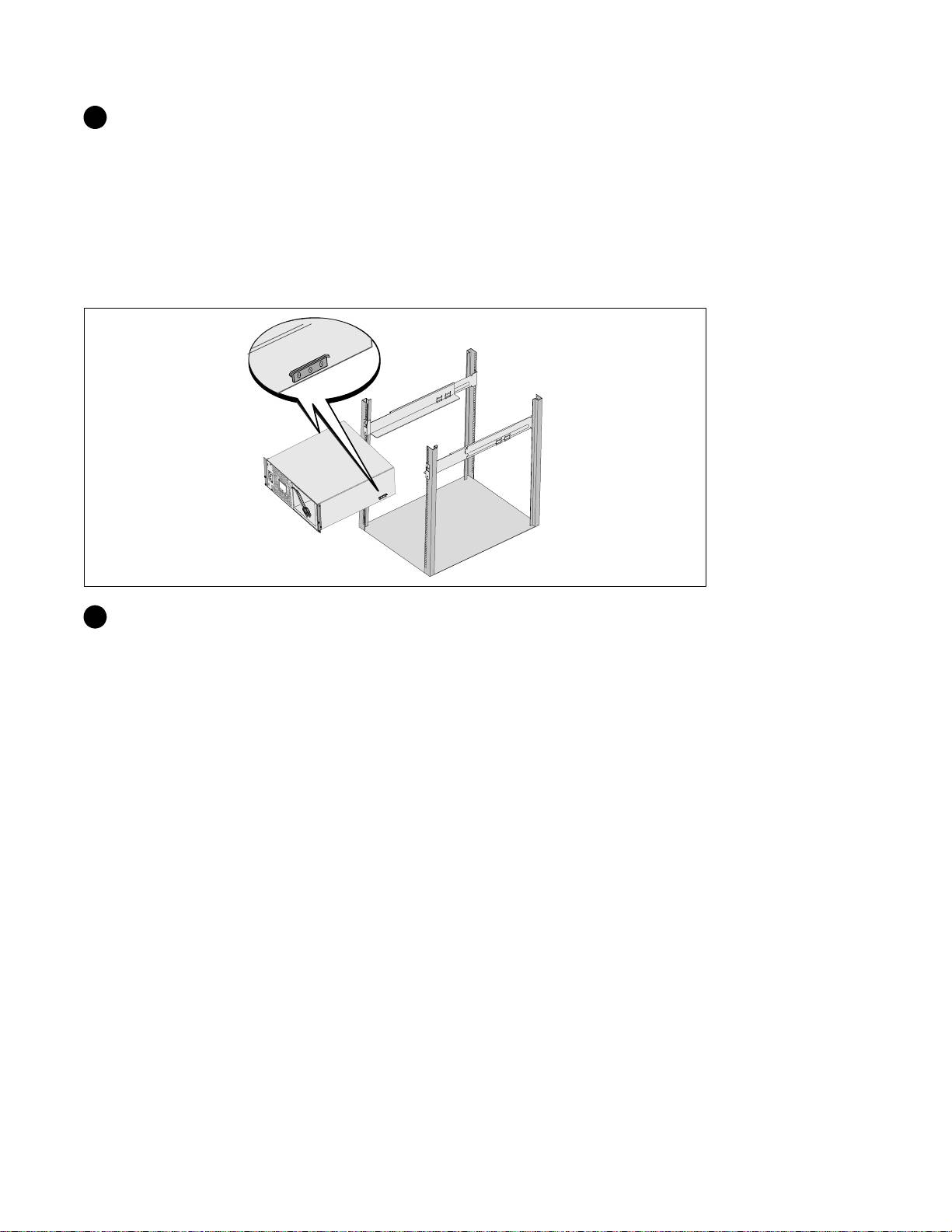
Installing the Cabinet
6 Slide the cabinet into the rack. Repeat for any a dditional cabinets.
Installation and Startup
|
13
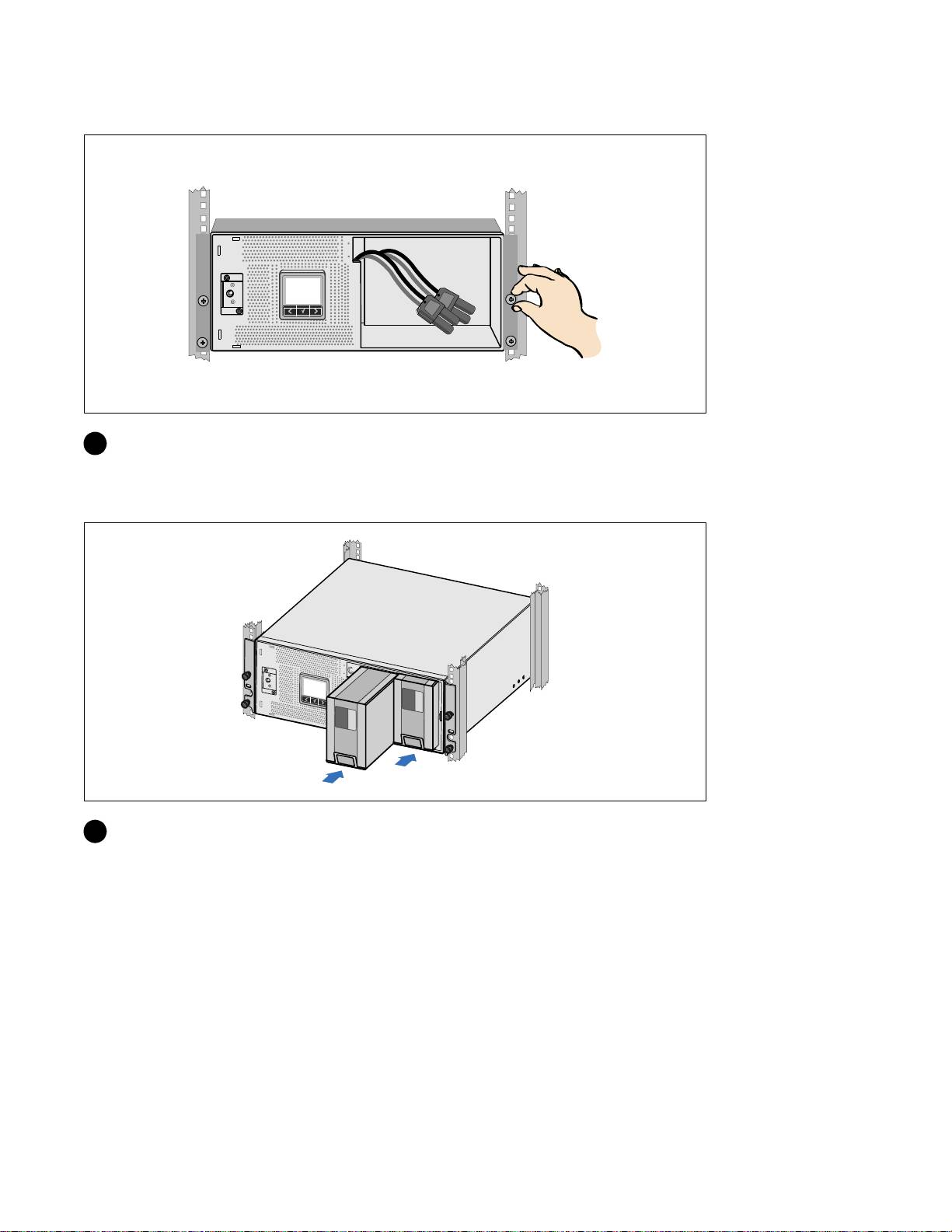
Securing the Cabinet
7 Secure the front of the cabinet to the rack using the thumbscrews on the mounting brackets.
Tighten by hand; do not use power tools. Repeat for any additional cabinets.
Installing the Battery Tray
8 Install the UPS battery trays.
14
|
Installation and Startup
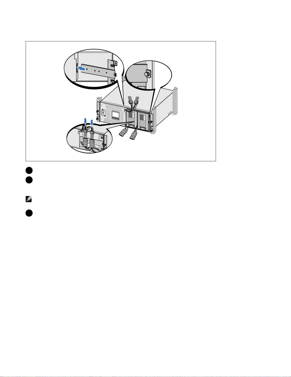
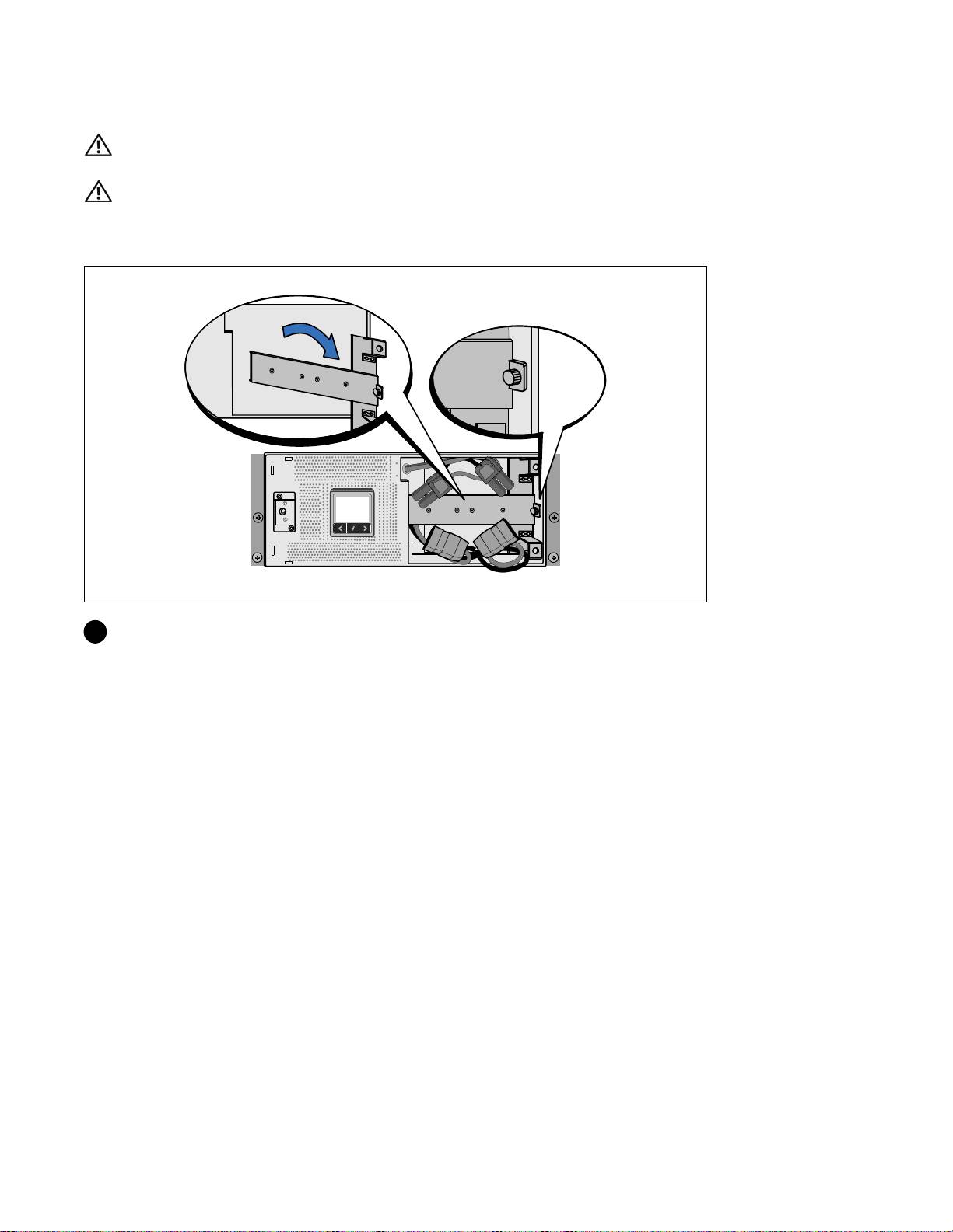
Replacing the Battery Retaining Bracket and Connecting the Internal Battery Connectors
9 Replace the battery retaining bracket.
10 Tighten the thumbscrew.
Torque the screw to 0.7 Nm (6.2 l b in).
NOTE:
A small amount of arcing may occur when connecting the batteries. This is normal and does not damage
the unit o r present any safety concern.
11 Connect the internal battery connectors and attach to the battery retaining bracket between the
two studs.
Installation and Startup
|
15
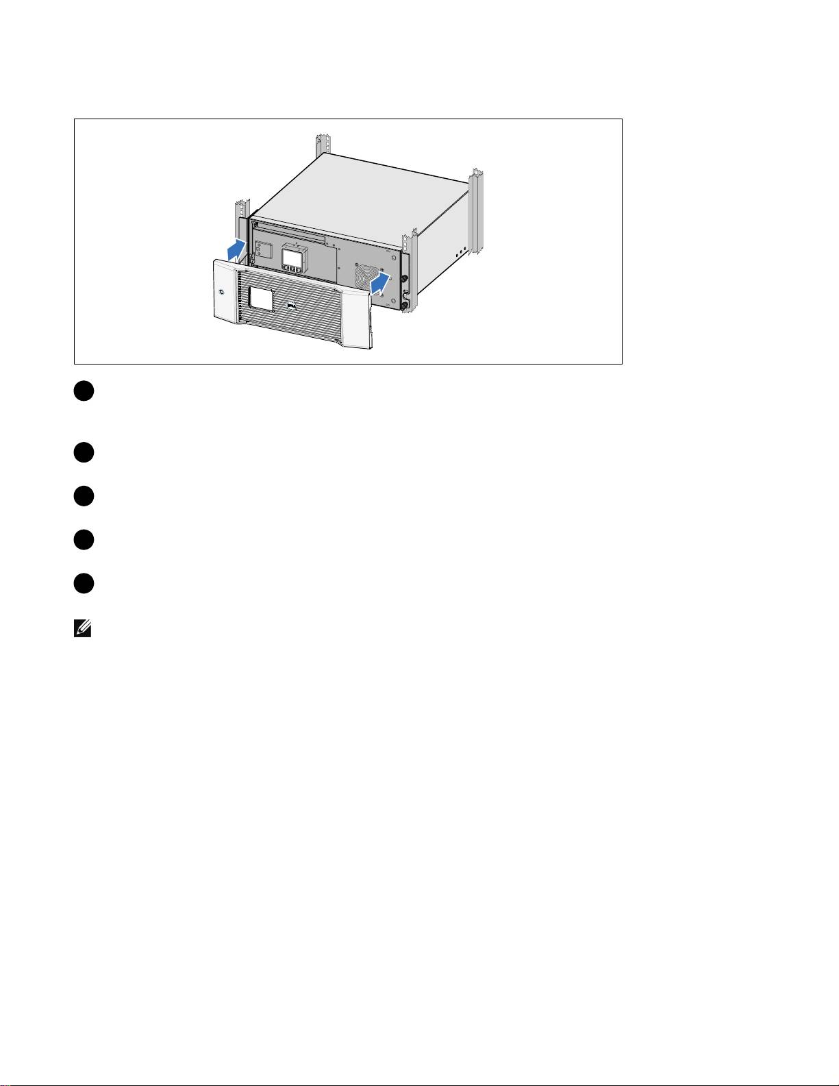
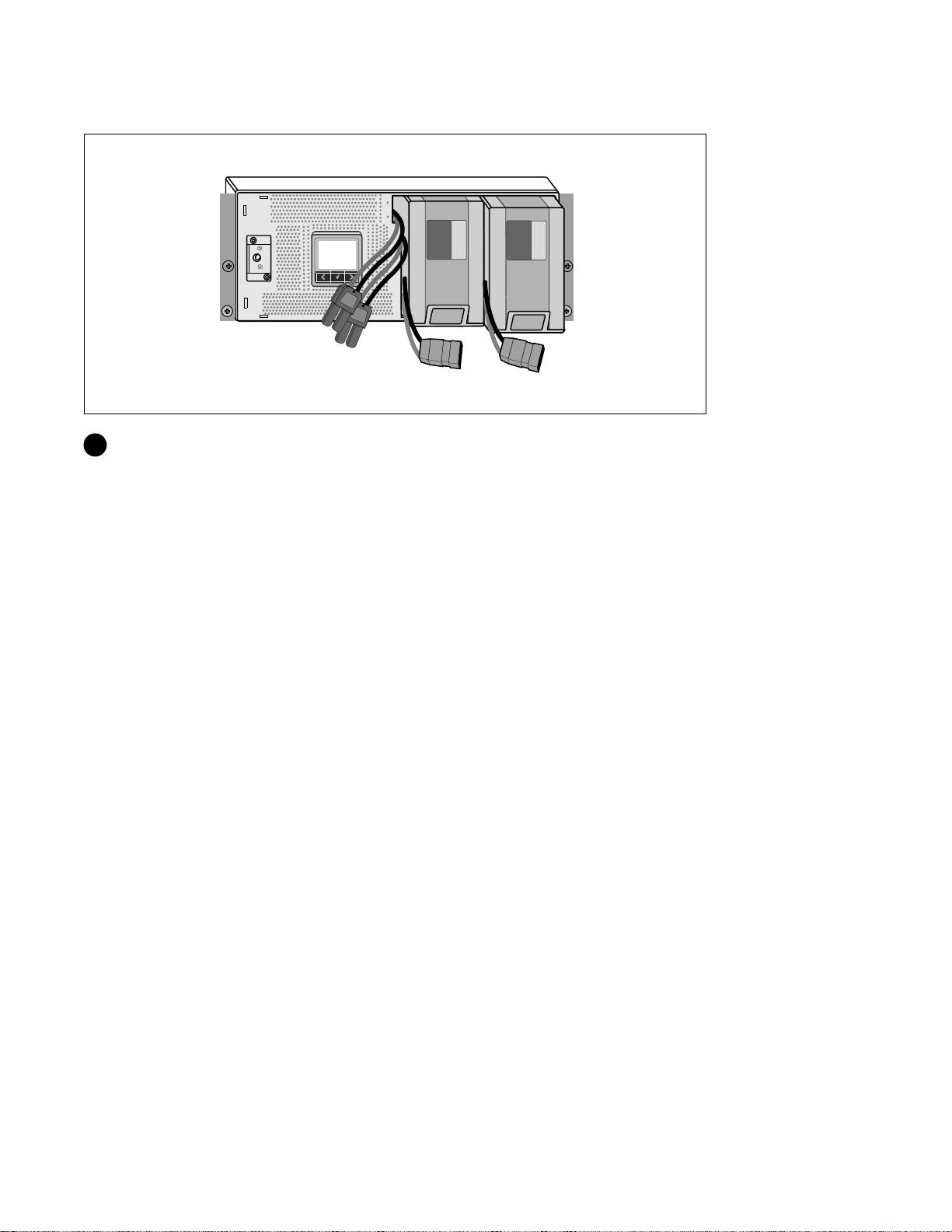
Installing the UPS Front Cover
12 Install the UPS front cover.
Connecting the Equipment
13
If you plan to use Dell UPS Management Software, connect your computer to the USB port using
the supplied cable.
14 If your rack has conductors for grounding or bonding of ungrounded metal parts, connect the
ground cable (not supplied) to the ground bonding screw.
15 If an emergency power-off (disconnect) switch is required by local codes, see “Installing Remote
Emergency Power-off” (REPO) in the Dell Online Rack UPS 3750W and 4200W User's Guide.
16 Plug the equipment to be protected into the UPS output receptacles, but do not turn on the
protected equipment.
NOTE:
Verify that the total equipment ratings do not exceed the UPS capacity to prevent an overload alarm.
16
|
Installation and Startup
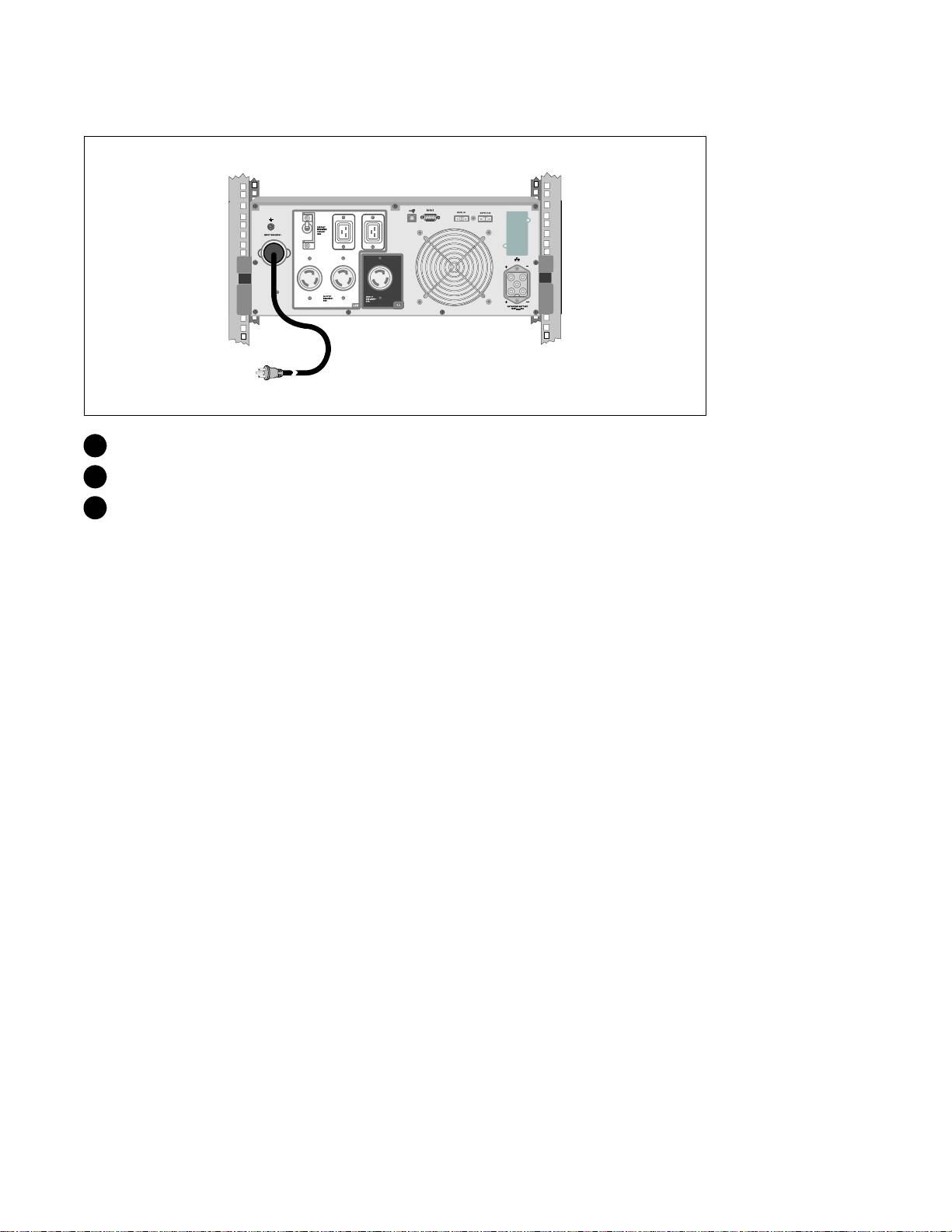
Connecting the Power Cord (3750W/208V Models Only)
1 Verify that the power input to the UPS has a minimum of 30A upstream overcurrent protection.
2 Plug the UPS power cord i nto a power outlet.
3 Continue to “Starting the UPS” on page 21.
Installation and Startup
|
17
Hardwiring the UPS Input
WARNING: Only qualified service personnel (such as a licensed electrician) shall perform the electrical
installation. Risk of electrical shock.
The Dell Online Rack hardwired models require a dedicated branch circuit that meets the following
requirements:
S 250V/30A, 2-pole circuit breaker (25A for 3750W/230V UPS models) to provide short circuit and
overcurrent protection
S The protection device requires a two-pole disconnection device between the UPS output and the
load (see Figure 6)
S The breaker must be wall-mounted and be readily accessible to the operator
S For Europe, the breaker must meet the IEC/EN 60934 standard and have a contact air gap of at
least 3 mm
S 200–240 Vac
S Single-phase (4200W/208V model is split-phase)
S 50/60 Hz
S Flexible metal conduit (recommended for ease of service and maintenance)
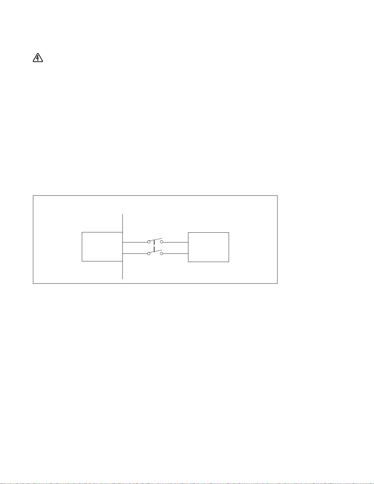
Wall
2-pole
Breaker
Line
AC Mains
UPS
Neutral
Figure 6. Circuit Breaker Diagram
18
|
Installation and Startup
